

Page 1
9330 Operating Manual
15-216 Revision B
9330 Operating Manual
Interface Inc. ● 7401 East Butherus Drive, Scottsdale, Arizona 85260 USA ● Phone 480.948.5555 ● Fax 480.948.1924
Document Number 15-216 Rev B Page 1 of 74
Page 2

9330 Operating Manual
Introduction
24-bit resolution
3750 Hz update rate
Peak and valley capture
Log to SD card at 1000Hz
USB Port with software
±5V analog output
Rechargeable battery
20 Hour battery life/300 hour standby
Stores up to 6 sensor calibrations
Powers up to 4x 350 ohm sensors
7 digit display
Description
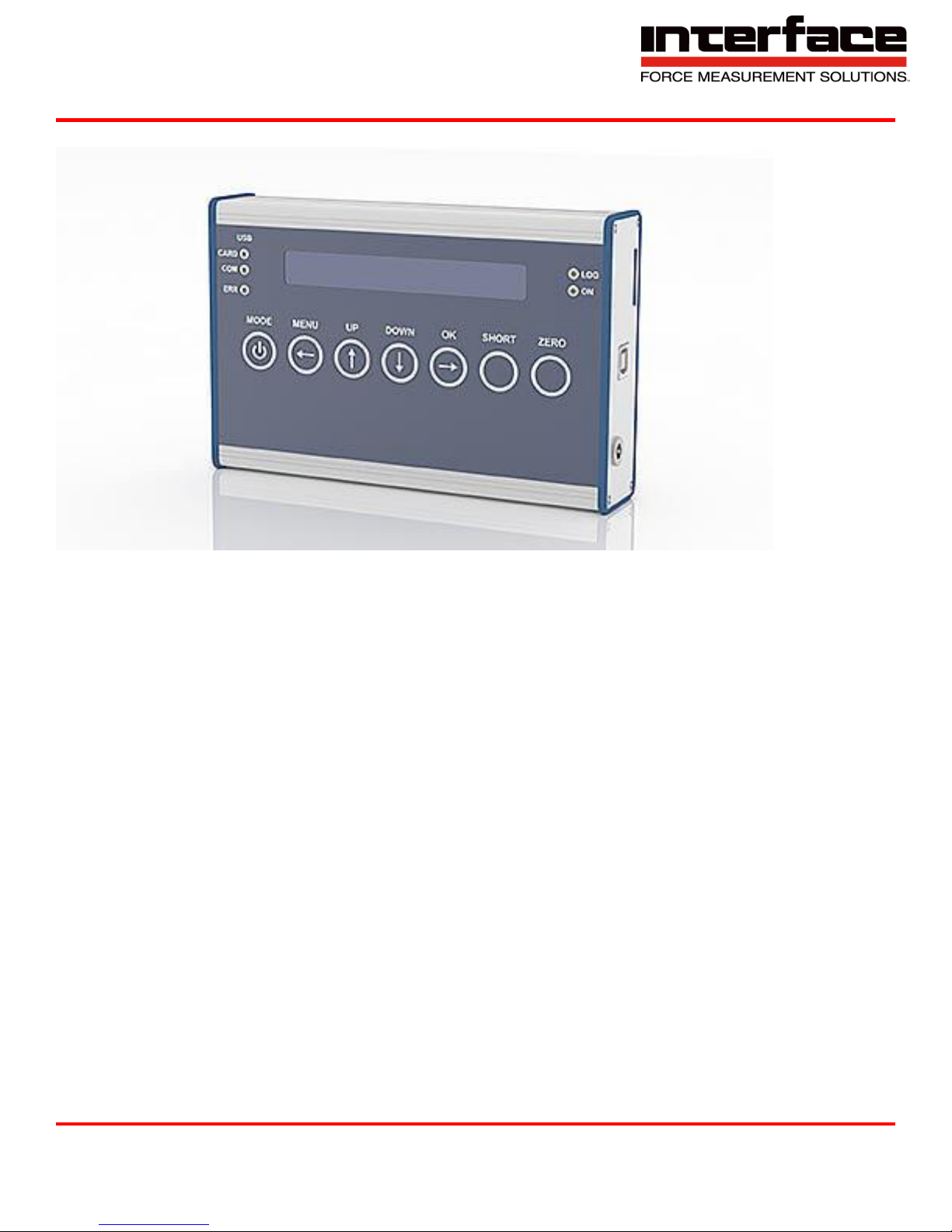
Model 9330 is a bipolar display, logging, amplifier that can be used in portable or desktop
applications. This instrument has an integrated bridge completion for 120 Ohm, 350 Ohm and 1000
Ohm strain gauges as well active sensors with 0…10V output signal. The measuring rate can be set
up to 3750 Hz. Data can be save to an SD Card at a rate of 1000 Hz or directly to the PC and 3750
Hz. This device also stores up to 6 sensor calibrations.
Options
IP65 Environmental Protection
SD Card – Class 10
Interface Inc. ● 7401 East Butherus Drive, Scottsdale, Arizona 85260 USA ● Phone 480.948.5555 ● Fax 480.948.1924
Document Number 15-216 Rev B Page 2 of 74
Page 3

9330 Operating Manual
Table of Contents
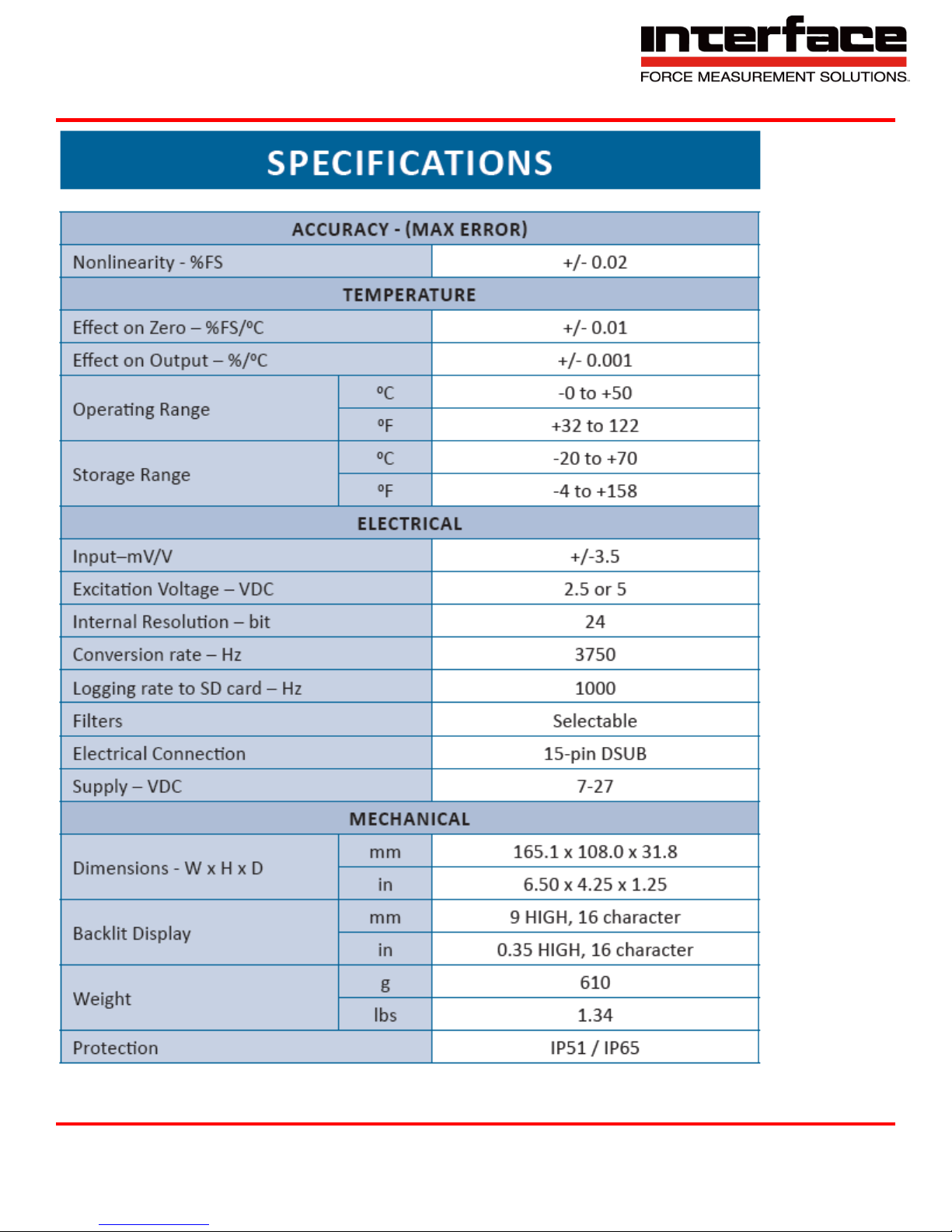
Specifications ........................................................................................................................................ 5
Dimensions ................................................................................................................................ ........... 6
Diagram ................................................................................................................................................ 6
Connection of Bridges ........................................................................................................................... 7
Pin Assignment ..................................................................................................................................... 8
Connection and Commissioning ........................................................................................................... 8
Menu Options ........................................................................................................................................ 9
Sensor Config. ......................................................................................................................... 10
Logger Config. .......................................................................................................................... 11
Options ..................................................................................................................................... 11
Data Acquisition ....................................................................................................................... 12
Set Scaling ............................................................................................................................... 12
Save Settings ........................................................................................................................... 13
Load Settings ........................................................................................................................... 13
Strain Analysis ......................................................................................................................... 14
Logger Menu ................................................................ ....................................................................... 15
Measuring Amplifier Menu .................................................................................................................. 17
Description of Buttons ......................................................................................................................... 19
Number Setting ................................................................................................................................... 19
Description of LEDs ............................................................................................................................ 19
Maximum, Minimum, and Mean Value ................................................................................................ 20
Recording Measured Data to File ....................................................................................................... 20
USB Operation .................................................................................................................................... 21
Power Supply per USB Connection .................................................................................................... 22
USB Driver ................................................................................................................................ .......... 22
BlueDAQ Software Installation ............................................................................................................ 22
COM Ports .......................................................................................................................................... 25
Adding a Channel ............................................................................................................................... 26
Distance Offset ................................................................................................................................... 30
Measurement and Recording .............................................................................................................. 31
BlueDAQ Menus ................................................................................................................................. 34
Interface Inc. ● 7401 East Butherus Drive, Scottsdale, Arizona 85260 USA ● Phone 480.948.5555 ● Fax 480.948.1924
Document Number 15-216 Rev B Page 3 of 74
Page 4

9330 Operating Manual
File ........................................................................................................................................... 34
View ......................................................................................................................................... 39
Action ................................................................ ................................ ....................................... 42
Device ...................................................................................................................................... 43
Channel .................................................................................................................................... 59
Sensor ................................ ................................ ...................................................................... 62
Options ..................................................................................................................................... 68
Help .......................................................................................................................................... 70
Interface Inc. ● 7401 East Butherus Drive, Scottsdale, Arizona 85260 USA ● Phone 480.948.5555 ● Fax 480.948.1924
Document Number 15-216 Rev B Page 4 of 74
Page 5
9330 Operating Manual
Interface Inc. ● 7401 East Butherus Drive, Scottsdale, Arizona 85260 USA ● Phone 480.948.5555 ● Fax 480.948.1924
Document Number 15-216 Rev B Page 5 of 74
Page 6
9330 Operating Manual
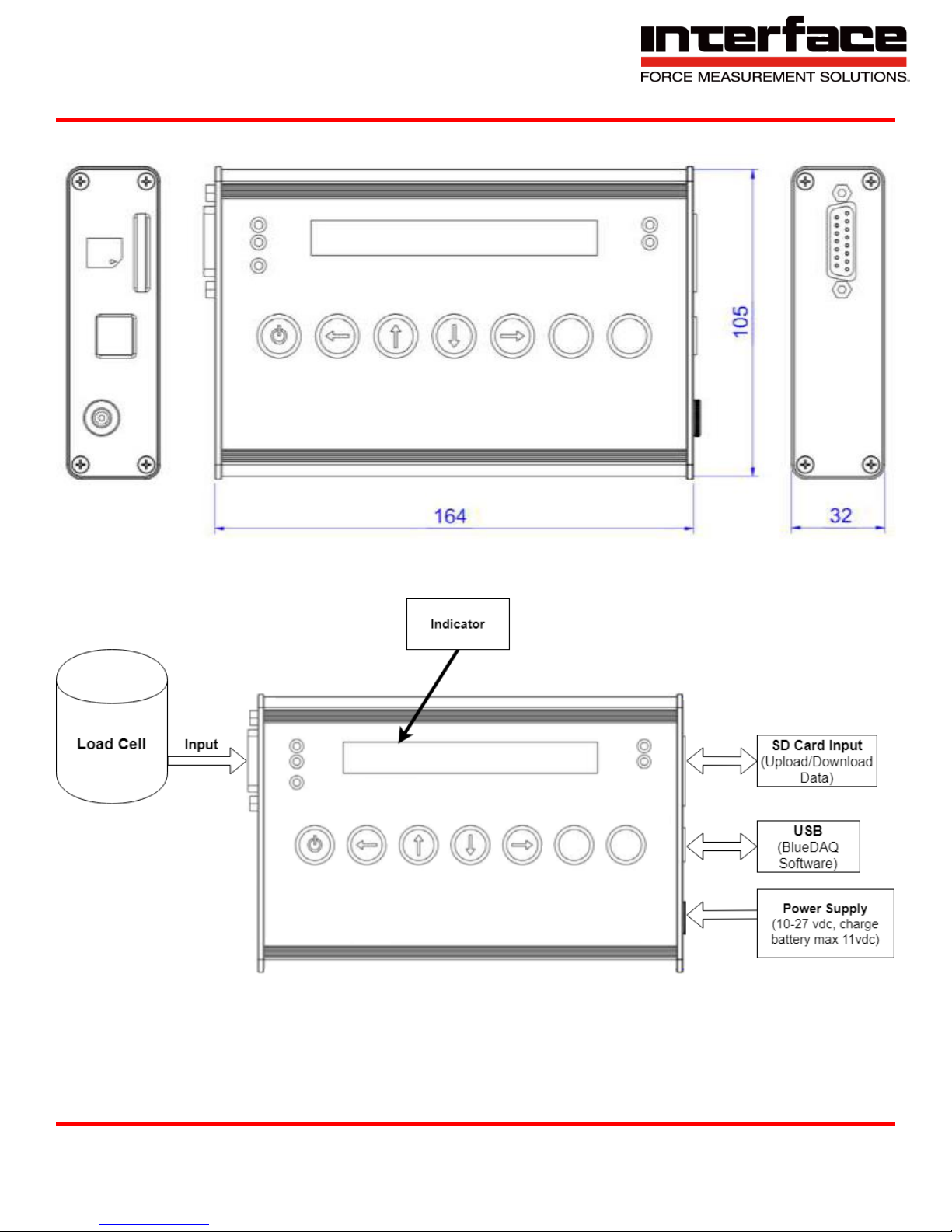
Dimensions
Diagram
Interface Inc. ● 7401 East Butherus Drive, Scottsdale, Arizona 85260 USA ● Phone 480.948.5555 ● Fax 480.948.1924
Document Number 15-216 Rev B Page 6 of 74
Page 7
9330 Operating Manual
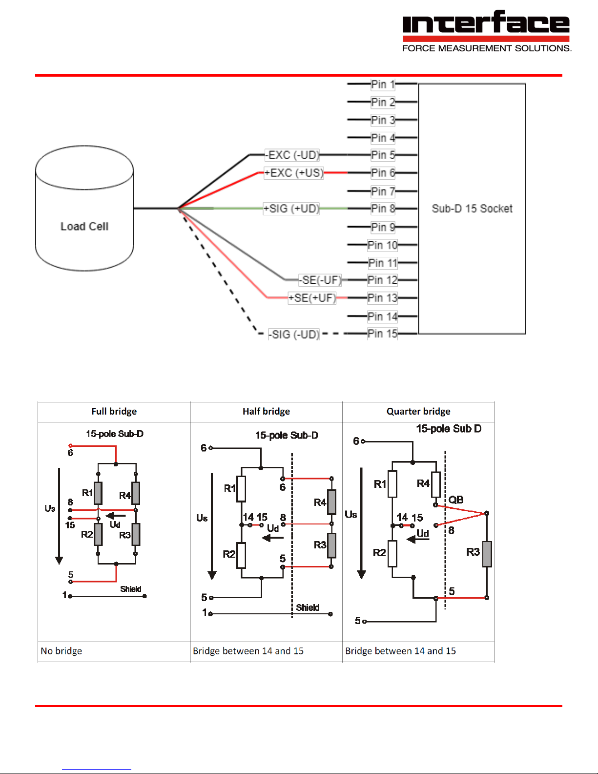
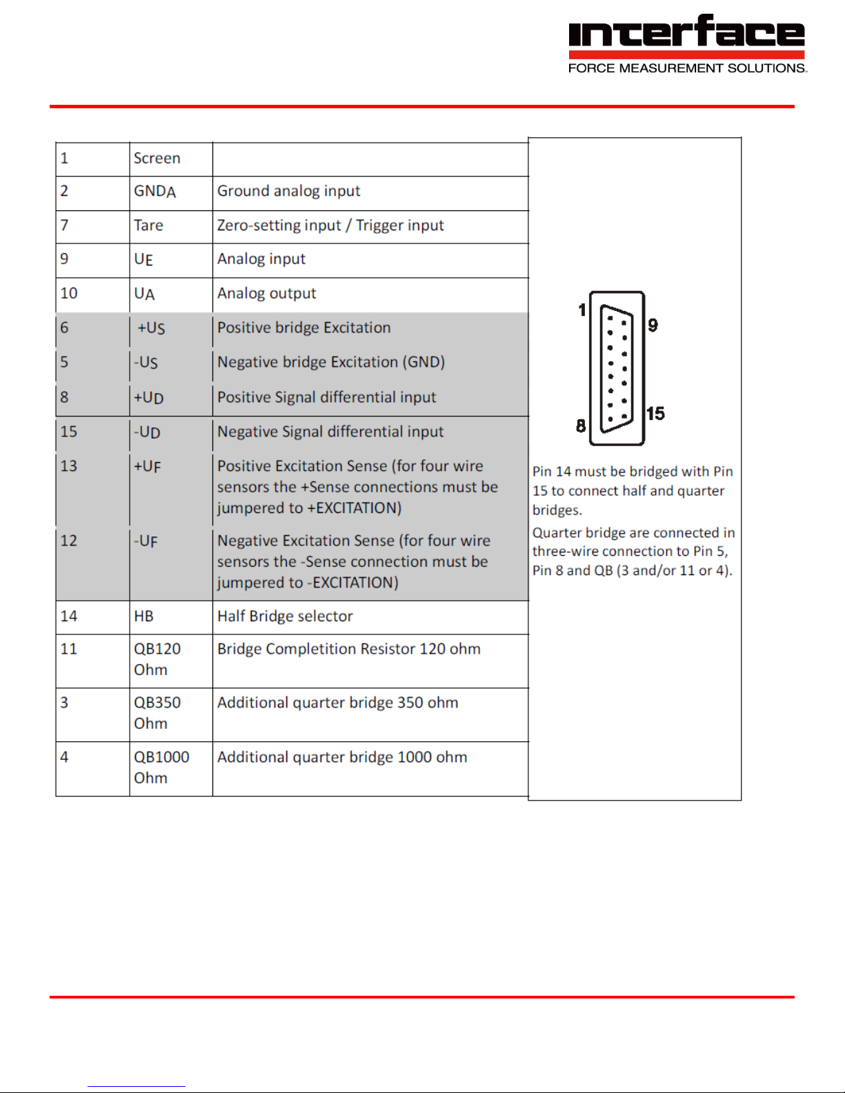
*** Note – Refer to Pin Assignment table ***
Connection of Bridges
Interface Inc. ● 7401 East Butherus Drive, Scottsdale, Arizona 85260 USA ● Phone 480.948.5555 ● Fax 480.948.1924
Document Number 15-216 Rev B Page 7 of 74
Page 8
9330 Operating Manual
Pin Assignment
Connection and Commissioning
To switch on, press the MODE button until the display is illuminated.
The device contains a battery that is charged by connecting the power adapter supplied.
The “ON” LED flashes while charging.
To switch off, hold the MODE button (outside the menu) down and confirm the following
message “Power off? (OK)“ by pressing the OK button.
Please use SDHC Memory Cards, class 6 or class 10, does not support UHS 2.
Interface Inc. ● 7401 East Butherus Drive, Scottsdale, Arizona 85260 USA ● Phone 480.948.5555 ● Fax 480.948.1924
Document Number 15-216 Rev B Page 8 of 74
Page 9
9330 Operating Manual
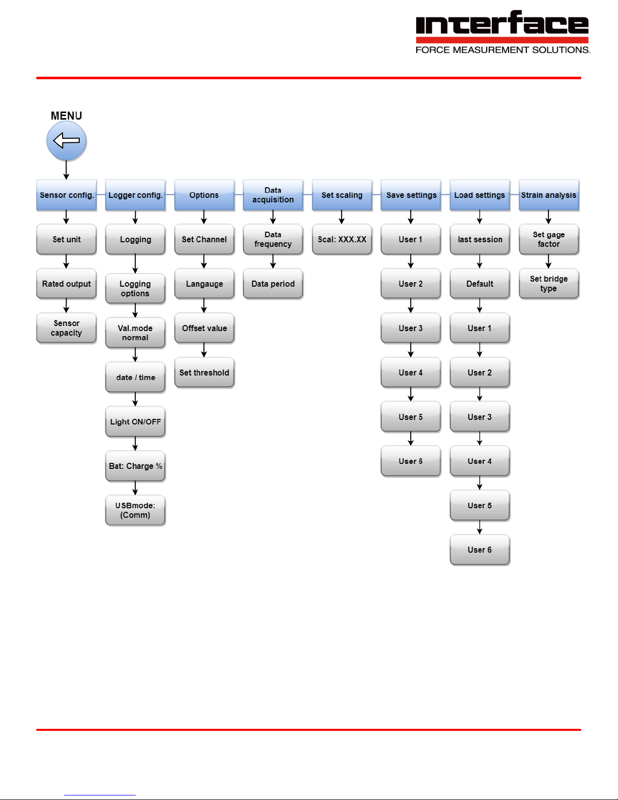
Menu Options
Interface Inc. ● 7401 East Butherus Drive, Scottsdale, Arizona 85260 USA ● Phone 480.948.5555 ● Fax 480.948.1924
Document Number 15-216 Rev B Page 9 of 74
Page 10
9330 Operating Manual
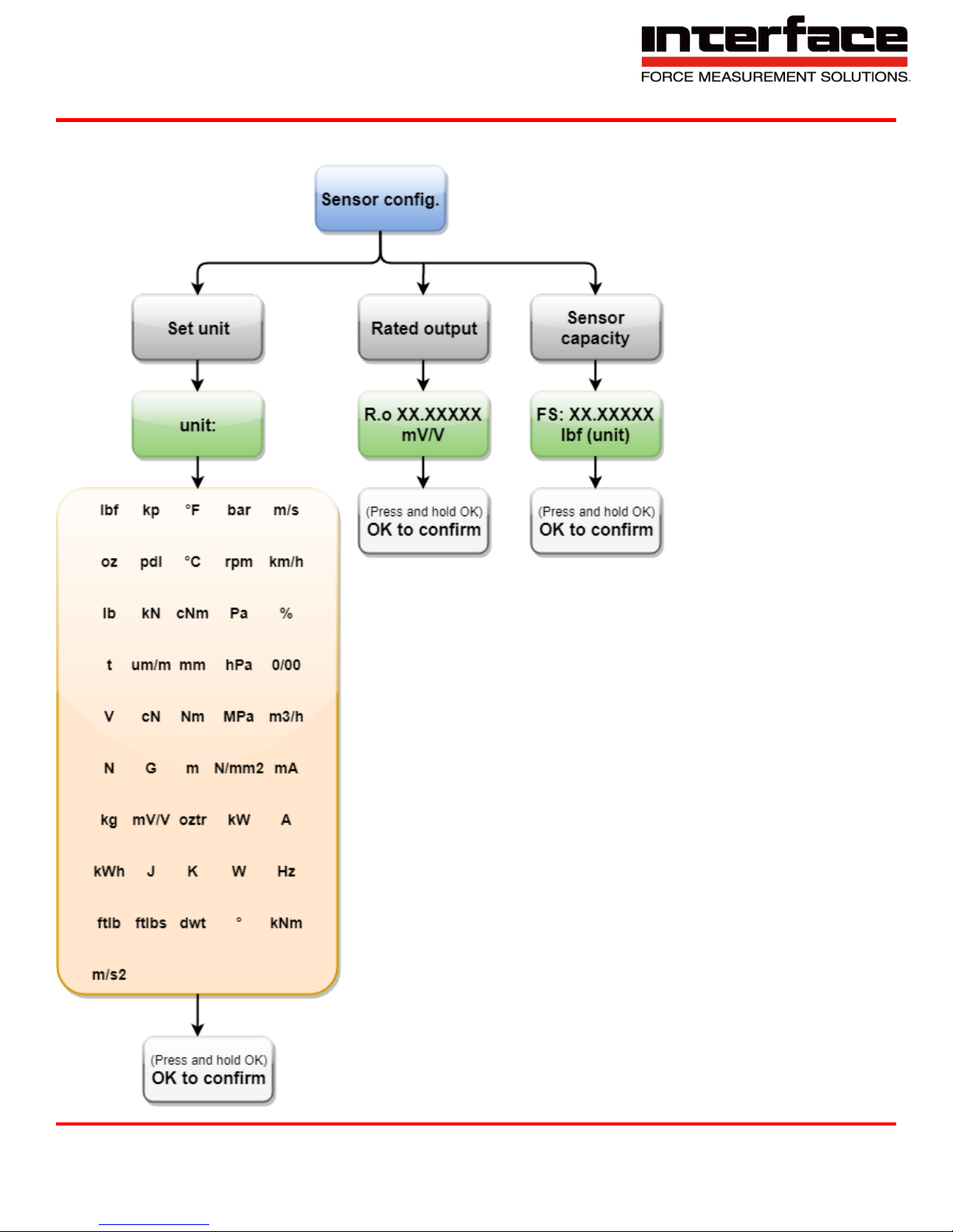
Sensor Config.
Interface Inc. ● 7401 East Butherus Drive, Scottsdale, Arizona 85260 USA ● Phone 480.948.5555 ● Fax 480.948.1924
Document Number 15-216 Rev B Page 10 of 74
Page 11
9330 Operating Manual
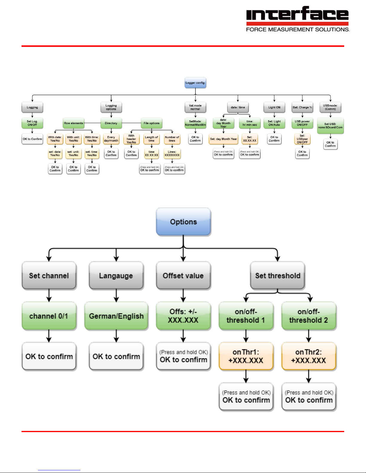
Logger Config.
Options
Interface Inc. ● 7401 East Butherus Drive, Scottsdale, Arizona 85260 USA ● Phone 480.948.5555 ● Fax 480.948.1924
Document Number 15-216 Rev B Page 11 of 74
Page 12
9330 Operating Manual
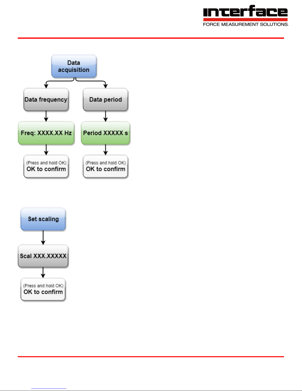
Data Acquisition
Set Scaling
Interface Inc. ● 7401 East Butherus Drive, Scottsdale, Arizona 85260 USA ● Phone 480.948.5555 ● Fax 480.948.1924
Document Number 15-216 Rev B Page 12 of 74
Page 13
9330 Operating Manual
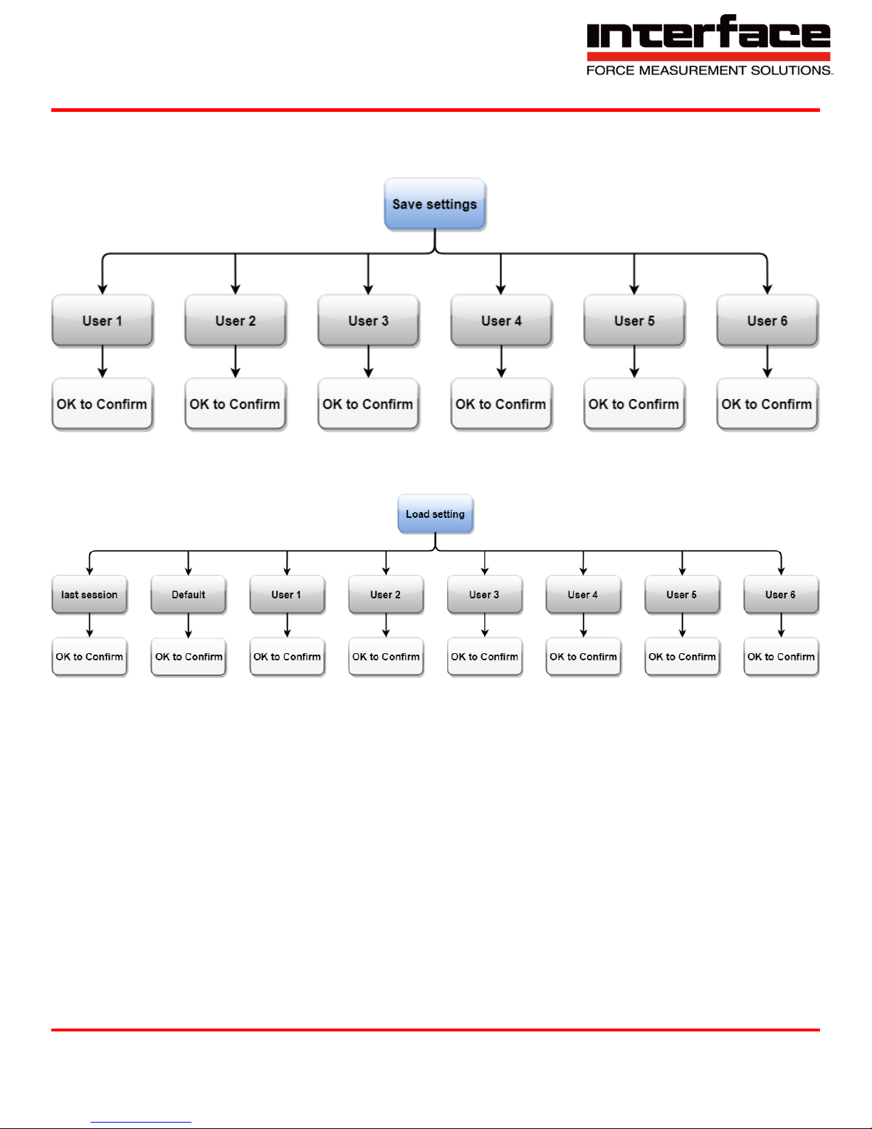
Save Settings
Load Settings
Interface Inc. ● 7401 East Butherus Drive, Scottsdale, Arizona 85260 USA ● Phone 480.948.5555 ● Fax 480.948.1924
Document Number 15-216 Rev B Page 13 of 74
Page 14
9330 Operating Manual
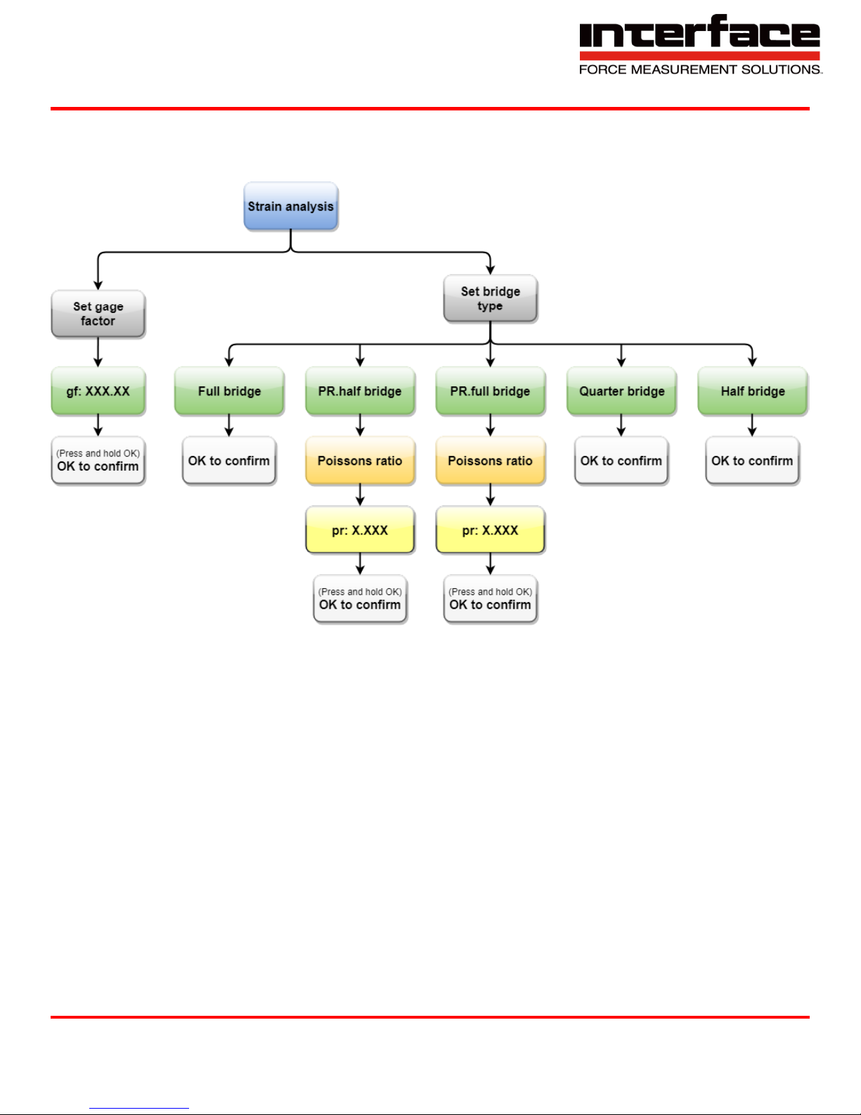
Strain Analysis
Interface Inc. ● 7401 East Butherus Drive, Scottsdale, Arizona 85260 USA ● Phone 480.948.5555 ● Fax 480.948.1924
Document Number 15-216 Rev B Page 14 of 74
Page 15
9330 Operating Manual
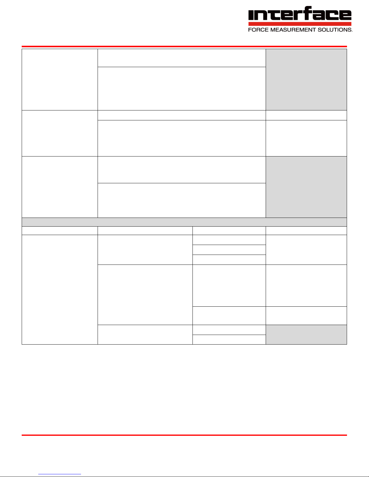
Menu Entry Level 1
Menu Entry Level 2
Menu Entry Level 3
Logging ON, OFF,
onOK
➔Set Log: ON – Permanent recording of
measured data on the SD card
➔Set Log: OFF No Recording
Set Log: onOK - Recording of measured data on
the SD
card as long as the OK button (at measured value
displayed) is pressed
USBmode: Comm,
SDcard, none
➔USBmode: SDcard The device is a Mass
Storage
Device when connected to the USB port, which
provides
access to the data on the SD card. Simultaneous
recording of measured value to file is not possible.
If
this mode is activated, recording is switched off.
➔USBmode: Comm The device is in serial USB
mode.
Our communication programs (e.g. GSVcontrol,
GSVmulti) can then be used. A standard driver is
loaded
when connected for the first time.
➔USBmode: none USB is switched off.
Bat: level bar or
Charge (with
Percentage display)
➔USB power: ON, OFF
If power supply is via USB port is enabled, the
GSV2MSD-DI can be supplied by the USB bus if it is
connected to a PC and configured as an USB
device. If the device is switched off, the battery
can be charged.
➔Set: USBpwr ON
➔Set USBpwr OFF
Switch power supply
via USB on or off
Logger Menu
The logger menu has the following functions:
View and set data recording mode on the SD memory card,
Select USB connection mode,
Select display illumination characteristics,
Display battery life,
Set date and time,
Select additional functions e.g. display and recording of maximum, minimum and average
measured values.
The Logger menu can be reached by pressing the MODE button from the measured value
display or via the last entry of the measuring amplifier main menu.
Interface Inc. ● 7401 East Butherus Drive, Scottsdale, Arizona 85260 USA ● Phone 480.948.5555 ● Fax 480.948.1924
Document Number 15-216 Rev B Page 15 of 74
Page 16
9330 Operating Manual
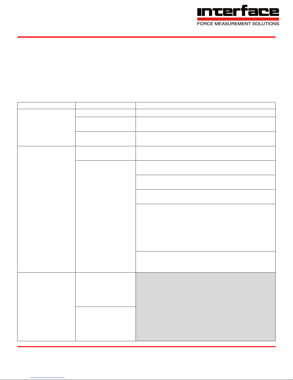
Light ON, Auto
➔Set: Light ON Display is permanently
illuminated
➔Set: Light Auto Display is illuminated when
buttons are
pressed and in the menu and goes out after 5
seconds this preserves the battery.
date / time
➔Date TT Mon JJJJ
➔Setting the date
➔Time HH:MM:SS
➔Setting the time
➔(see description of
numeric settings
below)
Val.mode normal,
MaxMin
➔SetMode: normal: Only displays the current
measured
values
➔SetMode: MaxMin:The maximum, minimum or
mean
value can be displayed in the display and all three
are recorded to file.
Menu Entry Level 1
Menu Entry Level 2
Menu Entry Level 3
Menu Entry Level 4
Logging Options
➔Row elements
➔With date: Yes/No
➔With […] Yes/No
i.e. switching to the
setting not yet selected
➔With time: Yes/No
➔With unit: Yes/No
➔File options
➔Number of lines
➔Setting the max.
number of lines in a
file
➔Length of time
➔Setting the max.
duration of the file
➔Directory
➔Every month
➔Every day
Notes
If a setting is in brackets in Level 1, this means that this setting has been selected but is not currently
active. This is the case if the conditions for this operating mode
are not met.
Example:
Logging (on): SD card is not inserted or write-protected or full or defective.
USBmode: (SDcard): USB cable is not connected or no SD card is inserted
Interface Inc. ● 7401 East Butherus Drive, Scottsdale, Arizona 85260 USA ● Phone 480.948.5555 ● Fax 480.948.1924
Document Number 15-216 Rev B Page 16 of 74
Page 17
9330 Operating Manual
Menu Entry Level 1
Menu Entry Level 2
Menu Entry Level 3
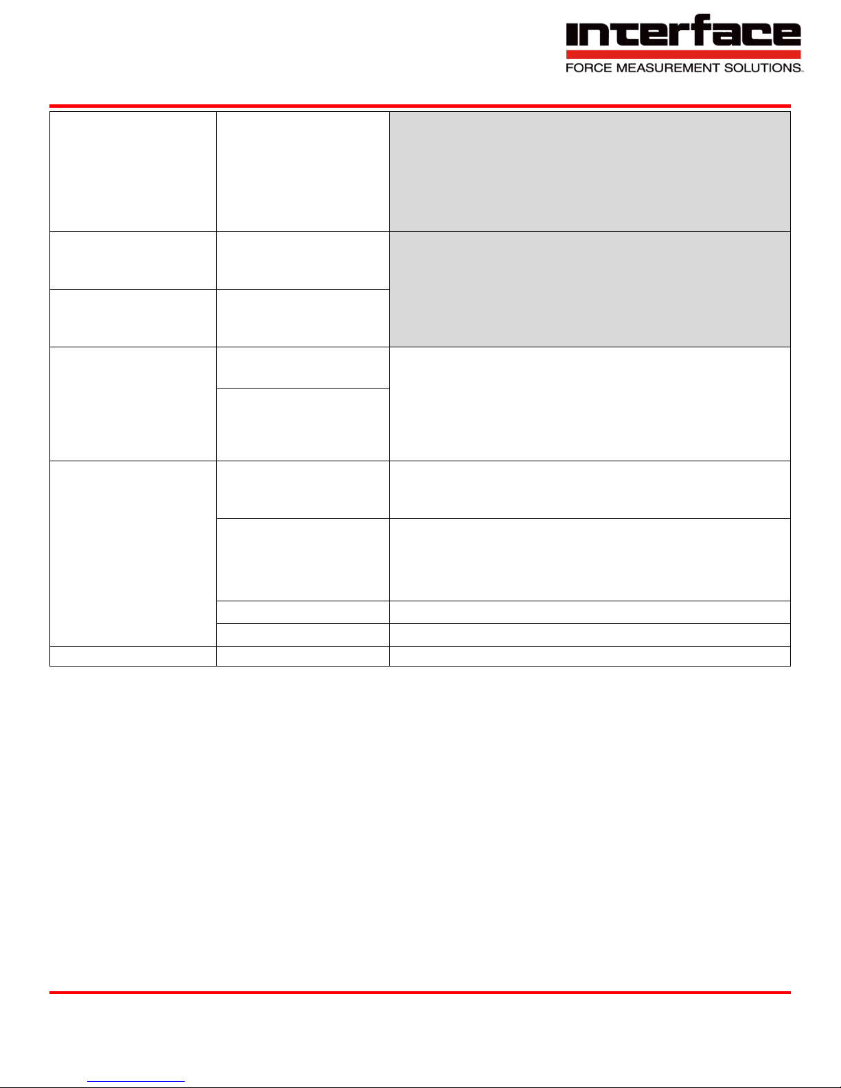
Sensor config.
➔unit
Select unit
➔Sensor capacity
Numeric setting of the physical nominal value of the
sensor
➔Rated output
Numeric setting of the electrical characteristic value
of the sensor
Strain analysis
➔Set gage factor
➔Numeric setting of the K-factor between 0.2 and
2583
➔Set bridge type
➔Full bridge: Full bridge circuit with 4 individual
DMS, all in longitudinal direction
➔Half bridge: Half bridge circuit with 2 individual
DMS, both in longitudinal direction
➔Quarter bridge: Quarter bridge circuit with one
DMS
➔PR.full bridge: Full bridge circuit with 4 individual
DMS, 2 in longitudinal direction and 2 in cross
direction
➔PR.half bridge: Half bridge circuit with 2 individual
DMS, one in longitudinal direction and
one in cross direction
Load settings
➔default:
Manufacturer’s
settings i.e. restoring
GSV-2 parameters to
default settings
➔user 1:
Userconfigurable
data set no.1 i.e.
loading the
parameters that were
Measuring Amplifier Menu
The measuring amplifier menu is used to set the parameters of the measuring amplifier, for example:
Sensor scaling factor
Unit
User-definable offset
Parameter memory
The measuring amplifier main menu can be reached by pressing the MENU button from the
measured value display.
Interface Inc. ● 7401 East Butherus Drive, Scottsdale, Arizona 85260 USA ● Phone 480.948.5555 ● Fax 480.948.1924
Document Number 15-216 Rev B Page 17 of 74
Page 18
9330 Operating Manual
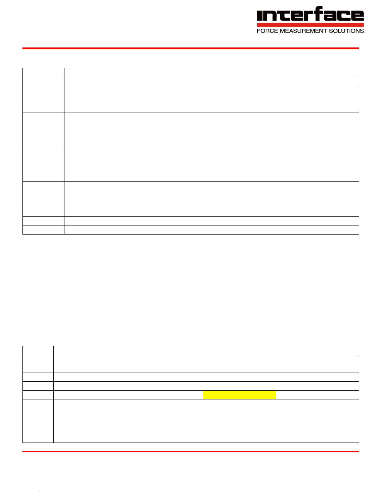
previously filed as
user 1
with save settings.
➔...and so on, until
➔user 6: like user 1,
but No 6
Save settings
Saves the current
configuration under
user 1 to user 6
Set scaling
Numerical value
between
0.1 ...999999
Data acquisition
➔Data frequency
Numerical value: Num. Of values per second
Numerical value: Data period of acquired values
Note: the last confirmed with OK value is
adopted. Please confirm data period for slow
measurements, data rate for fast
measurements.
➔Data period
Options
➔Set channel (Set
channel)
Numerical value 0 or 1
➔Set threshold (Set
threshold)
➔On-threshold Numerical value of the switch-on
threshold
➔Off-threshold Numerical value of the switch-off
threshold
➔Offset value
➔Value that is added to each measured value
➔Language
➔German or English (Menu language setting)
Logger config.
See logger menu.
Notes
Changing the unit does not change the measured value scaling!
Modification of the sensor measurement range or the characteristic value changes the scaling
of the measured value.
Modification of the DMS parameter of the strain analysis changes the scaling of the measured
value and the unit.
Access to the measuring amplifier menu will be blocked if communication is taking place via
the serial interface. In this case, the following is displayed: “Menu blocked”
1. Press the Menu button to go back one level.
2. Press the OK button to confirm an entry or to go to the next level.
3. If a setting is selected with the OK button, the following message will appear “OK to confirm“,
which you can confirm by pressing OK to approve the setting - or cancel by pressing the
MENU button.
Interface Inc. ● 7401 East Butherus Drive, Scottsdale, Arizona 85260 USA ● Phone 480.948.5555 ● Fax 480.948.1924
Document Number 15-216 Rev B Page 18 of 74
Page 19
9330 Operating Manual
Button
Function
MODE
To switch on and off or access the Logger menu
MENU
(LEFT)
To access the measuring amplifier menu, to go one menu level higher or to cancel an
entry.
For numeric settings: to move the cursor left.
UP
To move around the menu within the same level: switching to the next entry.
For measured value mode=MaxMin: to switch from one measured value display to the
next one up.
For numeric settings: to increase number and/or setting above the cursor.
DOWN
To move around the menu within the same level: switching to the previous entry.
For measured value mode=MaxMin: To switch from one measured value display to the
next one down.
For numeric settings: to decrease number and/or setting above the cursor.
OK
(RIGHT)
To confirm the entry or move down one level.
For measured value display and recording mode “with OK”: to record measured values
to file.
For numeric settings: to move the cursor right.
SHORT
To connect the +Ud and -Ud inputs (short-circuit of sensor signal)
ZERO
To trigger an automatic zero adjustment.
LED
Meaning
ON
Permanently on: Device on, no charging. Flashing slowly: Device off, battery charging.
Flashing faster: Device on, battery charging.
CARD
USB mass storage device active.
COM
USB serial communication mode active.
LOG
Measured data recording to SD card active. Do not remove card!
ERR
An error has occurred. Flashes permanently after switching on: the battery was empty,
therefore the date and time must be reset. Flashes alternately with ON after switching on
for approximately 3 seconds: the battery is empty, please connect power adapter to
charge. Flashes alternately with LOG: an error occurred whilst attempting to record
measured data e.g. the SD card may be write protected, full, incompatible or defective.
Description of the Buttons
Number Setting
To set a numerical value and the date or time, move the cursor right by pressing OK and left
by pressing MENU. The digit (and/or the month) above the cursor flashes and can be
increased or decreased using the UP / DOWN buttons.
For the setting to take effect, the OK button must be held down until the whole number flashes.
Then release the OK button, and the following message will appear “OK to confirm“. Confirm
this by pressing OK. To cancel the numeric setting, hold down the MENU button.
Description of LEDs
Interface Inc. ● 7401 East Butherus Drive, Scottsdale, Arizona 85260 USA ● Phone 480.948.5555 ● Fax 480.948.1924
Document Number 15-216 Rev B Page 19 of 74
Page 20

9330 Operating Manual
Date, Time
Value
Max
Min
Mean
Unit
13/05/03,15:38:31.99960
-0.0004
-0.0004
-3.0084
-0.0468
mV/V
Maximum, Minimum, and Mean Value
The maximum, minimum and mean value mode can be activated in the logger menu under Val.
mode. In this operating mode you can switch between these values and the current value in the
display using the UP and DOWN buttons. These values are written in every line in the measured
value file; in the order:
Current value, maximum, minimum and mean value. If activated, a header is written in the file, the
second line of which designates the corresponding column:
Scaling: +3,5000 Data frequency: 10,000 Hz
The header is only written when Recording options → File options → Header: Yes is selected in the
menu. In this operating mode, the maximum measured data rate for file recording is 1000 measured
values/s.
The following actions reset the determination of the maximum, minimum and mean value,
i.e. then re-determined with the subsequent measured values:
By switching on the device
By activating max./min./mean value mode
By zero setting
By starting permanent file recording
By ending manual file recording, i.e. by releasing the OK button
Recording Measured Data to File
If data recording is active, the 9330 creates directories on the SD card, which contain the measured
data files.
The directory name is created from the current date, depending on the directory mode setting. A new
directory is created every month in the initial state, with the name: G20JJ_MM, for example in
November 2012 this would be "G2012_11".
The name of the files within it are then formed based on the day and time, i.e.: DDHHMMSS.TXT. For
example, if a file is created on 14.11.2012 at 14:41:39, then the directory name is as above and the
file name: 14144139.TXT
The files are written in ASCII text format. Each measured value creates a line that is terminated with
<LF> and <CR>. Depending on the line settings, each line begins with the time stamp consisting of
date, time and fractions of seconds, then the measured value and the unit. The default setting for
lines is as follows (first line of the example above):
12/11/14,14:41:39.27669 -0.0011 mV/V
12/11/14,14:41:39.37669 -0.0011 mV/V
Interface Inc. ● 7401 East Butherus Drive, Scottsdale, Arizona 85260 USA ● Phone 480.948.5555 ● Fax 480.948.1924
Document Number 15-216 Rev B Page 20 of 74
Page 21

9330 Operating Manual
The date format satisfies the big-endian convention, i.e.
JJ/MM/DD
Date and time are separated by comma. The time format is
HH:MM:SS.bbbbb
Whereby the 5-digit fractions of seconds bbbbb, interpreted as a whole number, indicate 10μs steps.
In the example above, the data rate of the measuring amplifier is set to 10 measured values/seconds
((37669 - 27669) * 10μs = 100ms = 1/10 s).
Time stamp and measured value are separated with the tab character (‘/t’). Measured value and unit
are separated with a space.
The default setting for the maximum number of lines (i.e. displayed measured values) in a file is
32,000. As soon as this number is reached, a new file is opened.
In the “onOK” recording mode, whereby recording are only made by pressing the OK button, the data
sets (continuous lines during a recording) are written in the same file. After terminating a data set, i.e.
by releasing the OK button, the maximum number of lines is tested. If this is larger than or equal to
32000, a new file is opened. Therefore the number of lines can also be larger than 32000 in this
mode.
In this mode at least one line, i.e. one measured value, is written per data set. If you always want
exactly one measured value per data set, it is recommended that the data rate of the measuring
amplifier is set to a low value e.g. 1 measured value/second using communication software (e.g. 9330
control). By pressing OK, the device waits until a value is measured at records this value.
USB Operation
The USB operating mode can be selected in the logger menu at any time (see above), regardless of
whether the condition(s) for this operating mode are currently met or not - see note above. In the
latter case, the setting will be displayed in brackets in menu Level 1, and with an unchecked box
instead of a checked box in menu Level 2.
If a USB operating mode is currently active (i.e. the USB cable is connected to a PC) and the other is
selected, the current operating mode is switched off and the new mode is activated after 5 seconds. If
the host PC is equipped with speakers, you will hear the corresponding acoustic signal.
If the USB operating mode “SDcard” is selected and one of the recording modes is selected at the
same time, the recording will be switched off. In this Mass Storage mode, files on the SD card can be
read, written, deleted or formatted.
Interface Inc. ● 7401 East Butherus Drive, Scottsdale, Arizona 85260 USA ● Phone 480.948.5555 ● Fax 480.948.1924
Document Number 15-216 Rev B Page 21 of 74
Page 22

9330 Operating Manual
Power Supply per USB Connection
If the USB power supply “USB Power” is activated in the logger menu, the device can also be
powered via the USB port if it is connected to a host PC and fully configured. The battery is emptied
barely or not at all when switched on. When the device is switched off, the battery can be charged by
the host PC. In this state, the device is then an SD card reader, irrespective of the set USB mode.1 A
USB charging device cannot be used at this time.
USB Driver
The USB Mass Storage mode does not need a driver for Windows systems from Windows XP - once
the USB cable is connected a window will appear (depending on operating system settings), where
you can access the files; or you can reach the 9330 drive via “My computer” or with the Windows
explorer.
BlueDAQ Software Installation
1. Please follow these instructions carefully. DO NOT connect the amplifier to the PC until
instructed to do so. The BlueDAQ PC software is included on a USB Flash Drive with the amplifier
or can be downloaded from www.interfaceforce.com
2. Install the software by double-clicking the “setup.exe” file located in the BlueDAQ folder. You may
need to “Extract” the contents of the folder first if you downloaded it from the website. Follow the
instructions for installation. Once the software completes installation you MUST restart your
computer.
3. Attach the amplifier to the PC using the supplied USB A-B cable. BSC4, BSC8 and BX8 drivers
were installed with the BlueDAQ software and Windows will automatically load them. BSC8D/BX8
must be powered ON using supplied power cable and power switch. 9330 drivers must be
installed as described below.
4. When the device is connected in Communication mode for the first time, Windows will ask for a
driver directory. The installation process is described below. The driver is located on the USB
Flash drive supplied with the 9330. The Flash drive MUST be connected to the PC or the files
copied to the PC before connecting the 9330 to the PC.
5. Enable USB Communication mode. To do this, click the MODE button of the measuring amplifier
and select USBmode: Comm in the logger menu.
Interface Inc. ● 7401 East Butherus Drive, Scottsdale, Arizona 85260 USA ● Phone 480.948.5555 ● Fax 480.948.1924
Document Number 15-216 Rev B Page 22 of 74
Page 23
9330 Operating Manual
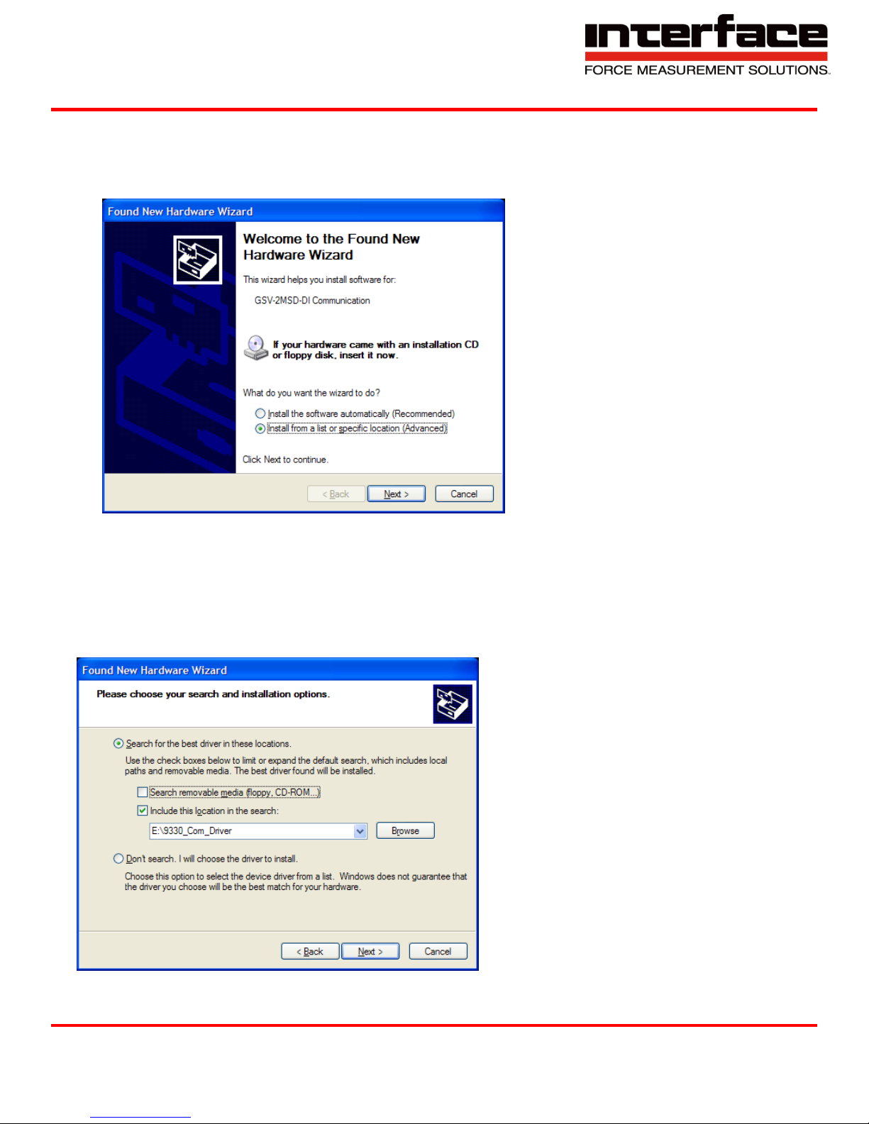
6. Now you can connect your 9330 to the PC via USB cable. Once connected the driver installation
window appears. Select “Install software from a list or specific source (advanced users)” and Click
“Next >”.
FIGURE 1 - FOUND NEW HARDWARE WIZARD
7. Click “Search for the best driver in these locations”
8. Check the option “Include this location in the search:” and then click “Browse”. Select the folder:
9330_Com_Driver from the supplied USB drive and Click “Continue >”.
FIGURE 2 - NEW HARDWARE WIZARD
Interface Inc. ● 7401 East Butherus Drive, Scottsdale, Arizona 85260 USA ● Phone 480.948.5555 ● Fax 480.948.1924
Document Number 15-216 Rev B Page 23 of 74
Page 24
9330 Operating Manual
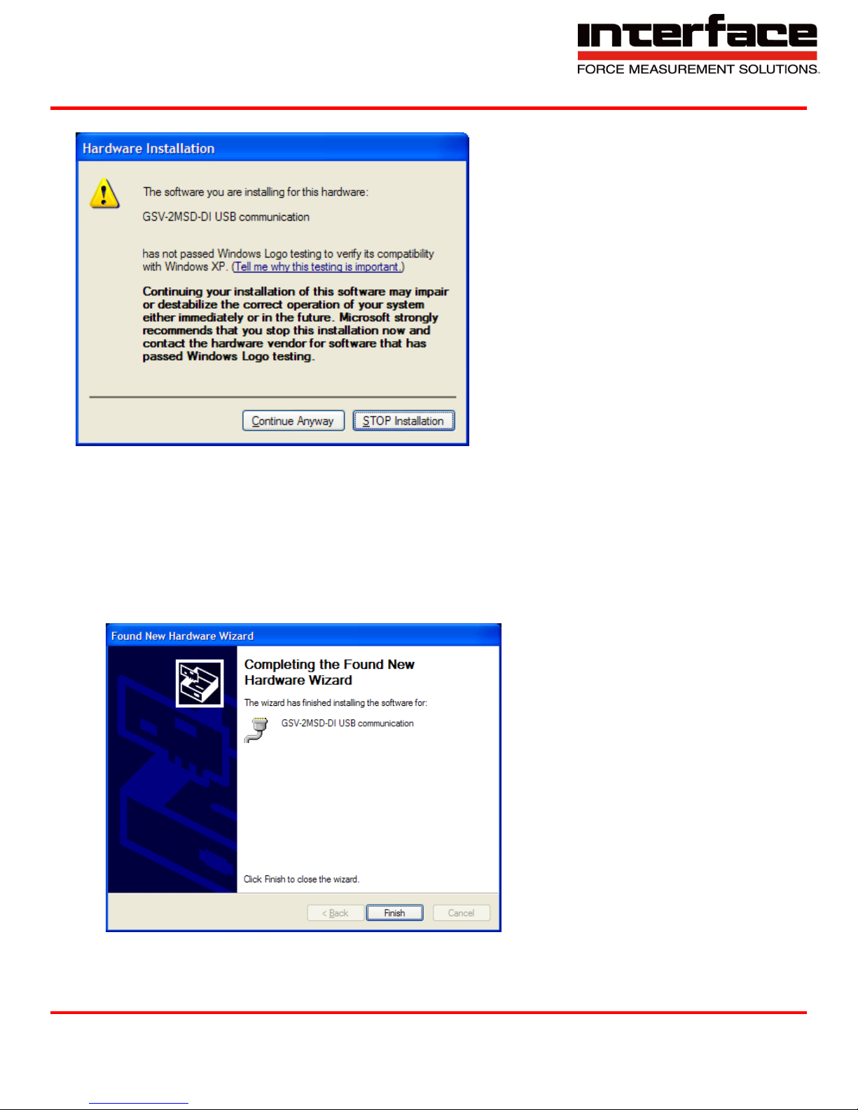
9. In the dialogue window “Hardware installation” click “Continue installation”.
FIGURE 3 - HARDWARE INSTALLATION
10. The driver was installed successfully. Click “Finish”.
FIGURE 4 - HARDWARE INSTALL FINISH
Interface Inc. ● 7401 East Butherus Drive, Scottsdale, Arizona 85260 USA ● Phone 480.948.5555 ● Fax 480.948.1924
Document Number 15-216 Rev B Page 24 of 74
Page 25
COM Ports
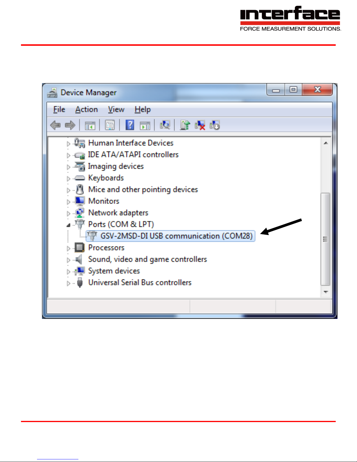
Once windows is finished installing the device navigate to Device Manager and check for a
new USB Serial Port (COMX) where X is the assigned port number. Remember this number.
In the examples below it is COM28
9330 Operating Manual
FIGURE 5 - EXAMPLE OF 9330 COMPORT
Interface Inc. ● 7401 East Butherus Drive, Scottsdale, Arizona 85260 USA ● Phone 480.948.5555 ● Fax 480.948.1924
Document Number 15-216 Rev B Page 25 of 74
Page 26
9330 Operating Manual
BSC2 Will be
selected
Input Channel
will not be
available
Adding a Channel
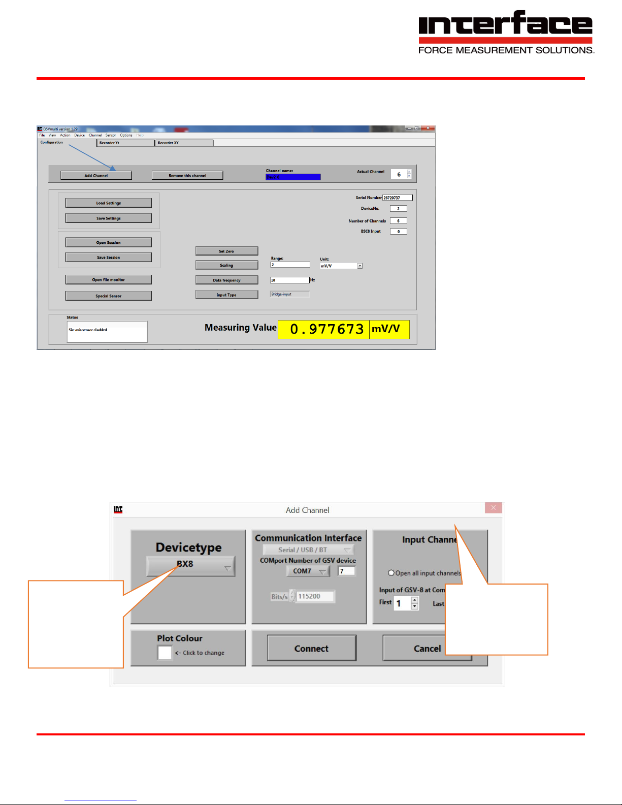
Run BlueDAQ from the start menu. After the program launches click “ADD CHANNEL”
FIGURE 6 - ADD CHANNEL
1. In the Add Channel dialog box
1.1. Click Devicetype drop-down and select BSC4, BSC8, BX8, or BSC2 (9330)
1.2. Click the Device dropdown box and select the device, select the COM Port (See Device
Manager if unknown) and open the correct amount of input channels (First = 1 and Last =
total # of channels for device). For Model 9330, you will not be allowed to change the
number of channels.
1.3. Click Connect
FIGURE 7 - ADD CHANNEL MENU
Document Number 15-216 Rev B Page 26 of 74
Interface Inc. ● 7401 East Butherus Drive, Scottsdale, Arizona 85260 USA ● Phone 480.948.5555 ● Fax 480.948.1924
Page 27
9330 Operating Manual
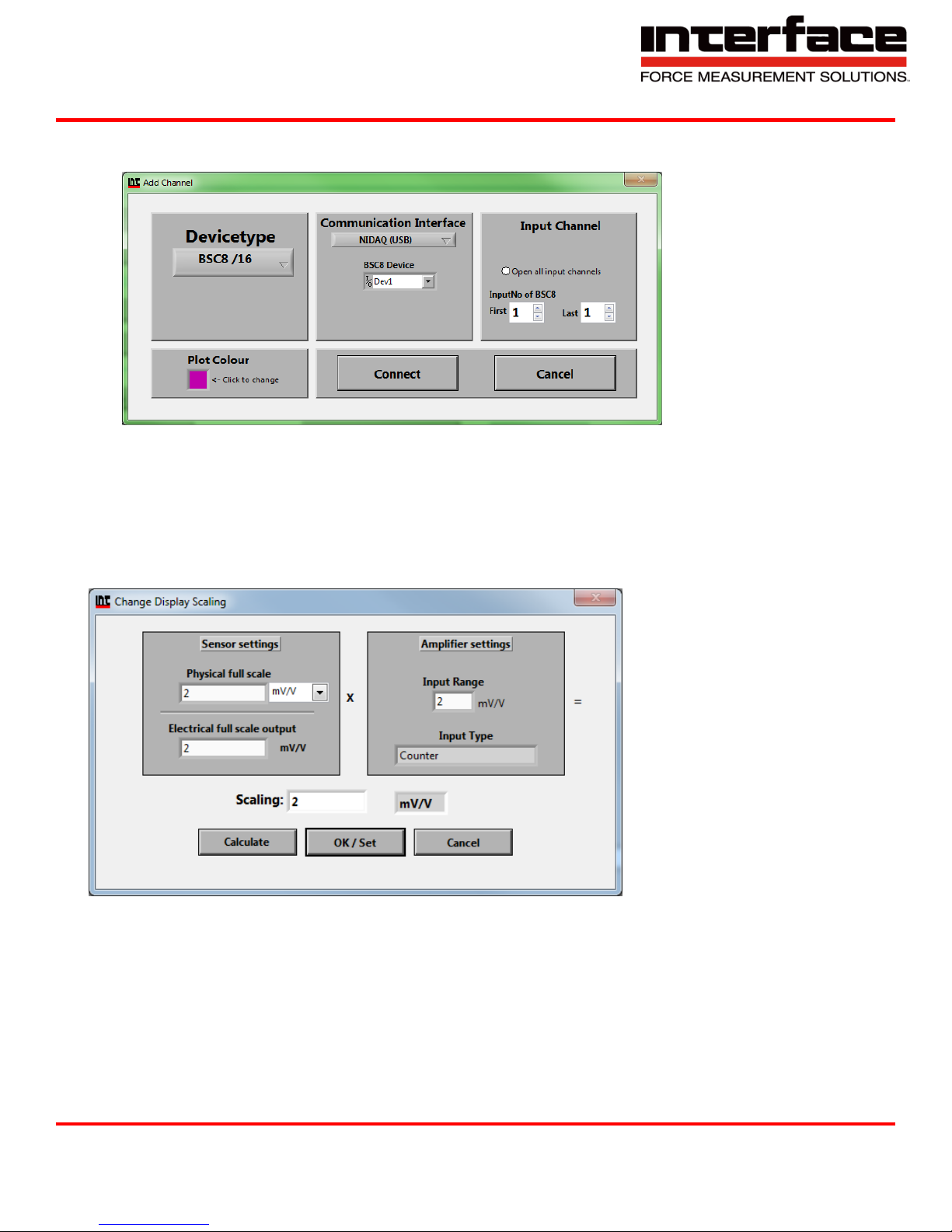
2. BSC8 has a slightly different add channel box. Select Dev1 instead of Com port. Please
remember to open the needed amount of input channels.
FIGURE 8 - EXAMPLE BSC8 DEVICE
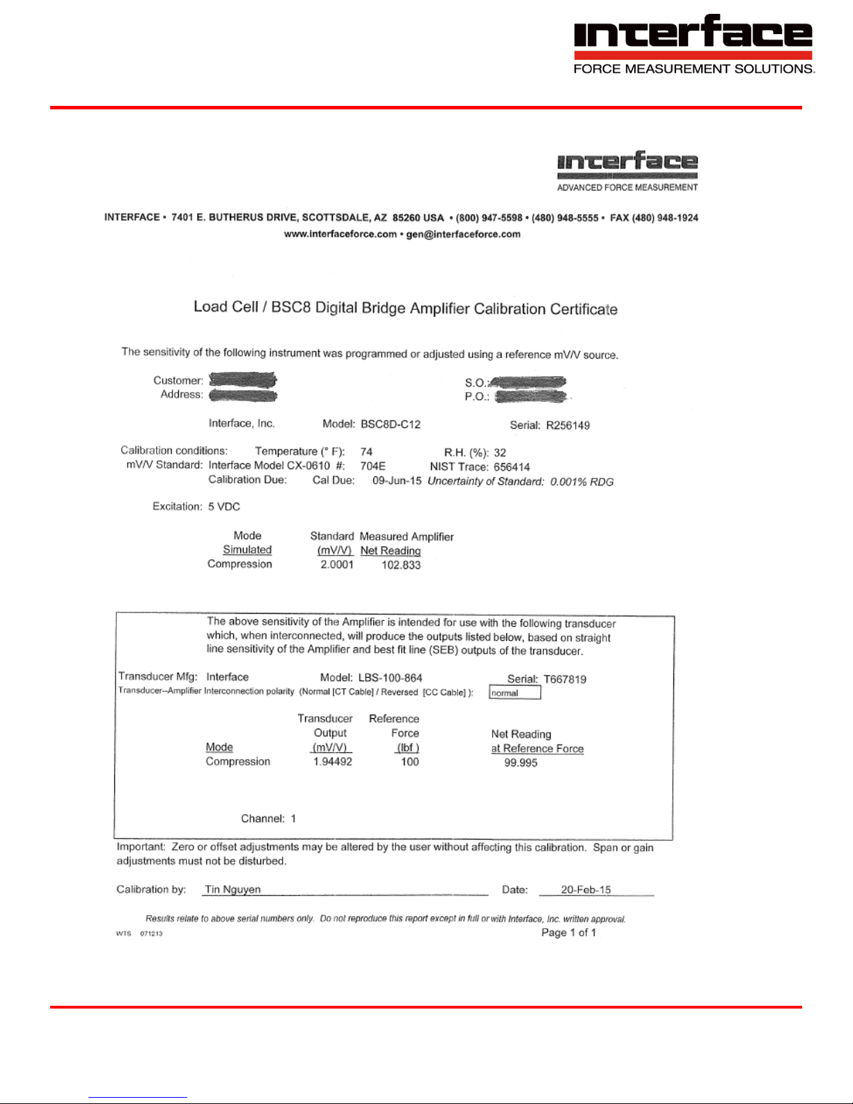
3. Each channel must now be scaled using the “SCALING” dialog box. Each channel must be scaled
independently. If the BSC8 was purchased with Interface load cells and a System Setup and
Scaling then the scaling values will be taken from the “Load Cell / BSC8 Digital Bridge Amplifier
Calibration Certificate”
4.
FIGURE 9 - EXAMPLE OF SCALING
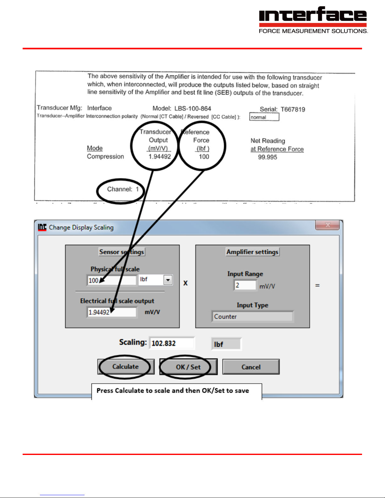
4.1. Physical full scale is typically the capacity of the sensor.
4.2. Electrical full scale output is the output of the sensor at the Physical full scale.
4.3. Input Range is always 2 mV/V and should not be changed.
Interface Inc. ● 7401 East Butherus Drive, Scottsdale, Arizona 85260 USA ● Phone 480.948.5555 ● Fax 480.948.1924
Document Number 15-216 Rev B Page 27 of 74
Page 28
9330 Operating Manual
5. Example scaling using Load Cell / BSC8 Digital Bridge Amplifier Calibration Certificate”
FIGURE 10 - CALIBRATION DATA SHEET – AMPLIFIER CALIBRATION CERTIFICATE
Interface Inc. ● 7401 East Butherus Drive, Scottsdale, Arizona 85260 USA ● Phone 480.948.5555 ● Fax 480.948.1924
Document Number 15-216 Rev B Page 28 of 74
Page 29
9330 Operating Manual
FIGURE 11 - SCALING USING CALIBRATION CERTIFICATE
Interface Inc. ● 7401 East Butherus Drive, Scottsdale, Arizona 85260 USA ● Phone 480.948.5555 ● Fax 480.948.1924
Document Number 15-216 Rev B Page 29 of 74
Page 30
9330 Operating Manual
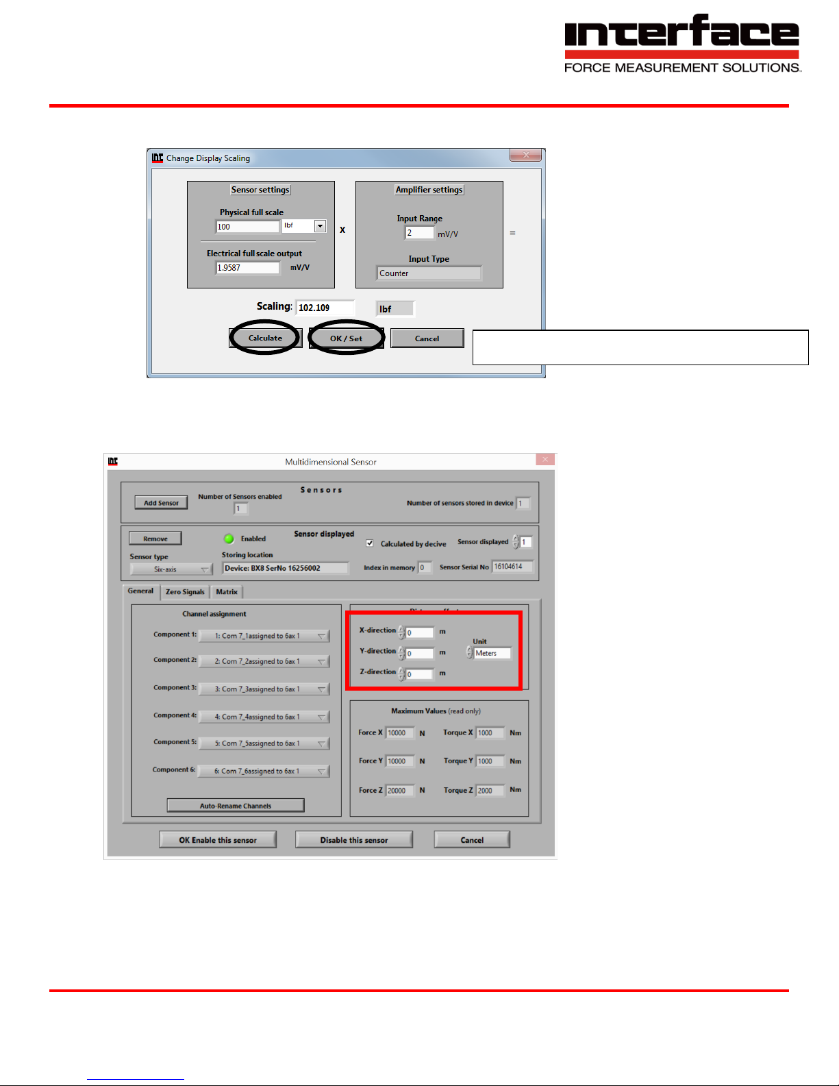
Press Calculate to scale and then OK/Set to save
6 Example scaling a channel using model WMC-100 load cell with 100 lbf capacity and 1.9587
mV/V output. After entering the values into the dialog box you must click “Calculate” and then
“OK/Set”.
FIGURE 12 - EXAMPLE OF CALIBRATION FOR A WMC-100 LOAD CELL
Distance Offset
1. To change the distance of the origin, this setting may be access in the sensor option
2. Select the corresponding direction and the distance.
3. Can be set in meters or millimeters.
Interface Inc. ● 7401 East Butherus Drive, Scottsdale, Arizona 85260 USA ● Phone 480.948.5555 ● Fax 480.948.1924
Document Number 15-216 Rev B Page 30 of 74
Page 31
9330 Operating Manual
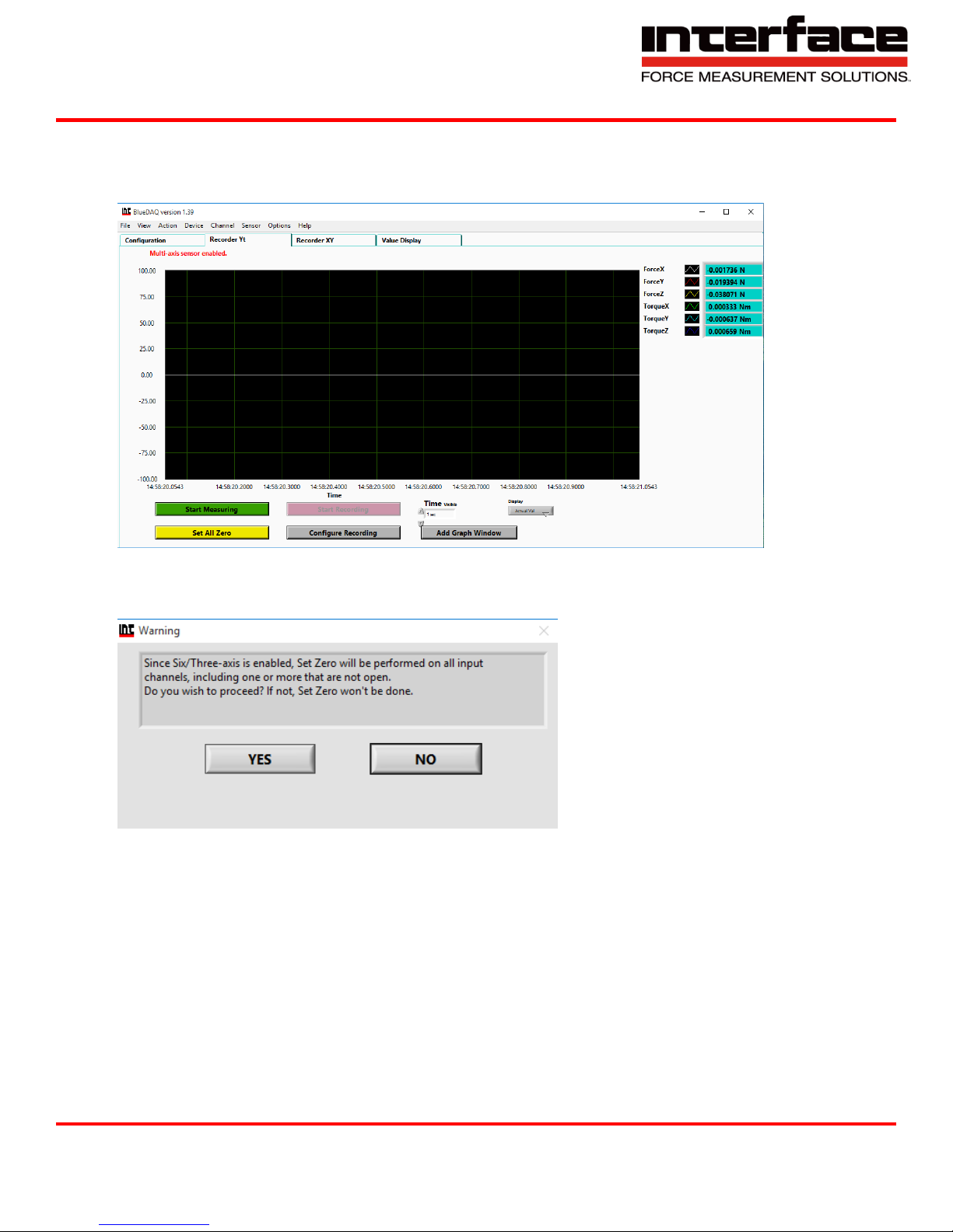
Measurement and Recording
1. Click Set All Zero before measuring
FIGURE 13 - ZERO VALUES
2. Click YES
FIGURE 14 – PROCEED WITH ZERO RESET
Interface Inc. ● 7401 East Butherus Drive, Scottsdale, Arizona 85260 USA ● Phone 480.948.5555 ● Fax 480.948.1924
Document Number 15-216 Rev B Page 31 of 74
Page 32
9330 Operating Manual
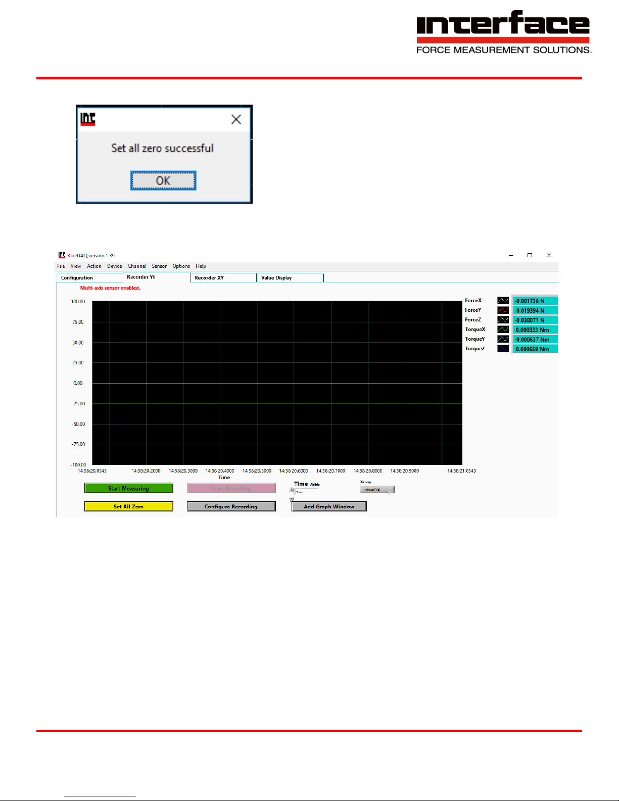
3. Click OK to Start Measuring
FIGURE 15 - SUCCESSFUL ZERO
4. Click Start Measuring
FIGURE 16 - MEASUREMENT
Interface Inc. ● 7401 East Butherus Drive, Scottsdale, Arizona 85260 USA ● Phone 480.948.5555 ● Fax 480.948.1924
Document Number 15-216 Rev B Page 32 of 74
Page 33
9330 Operating Manual
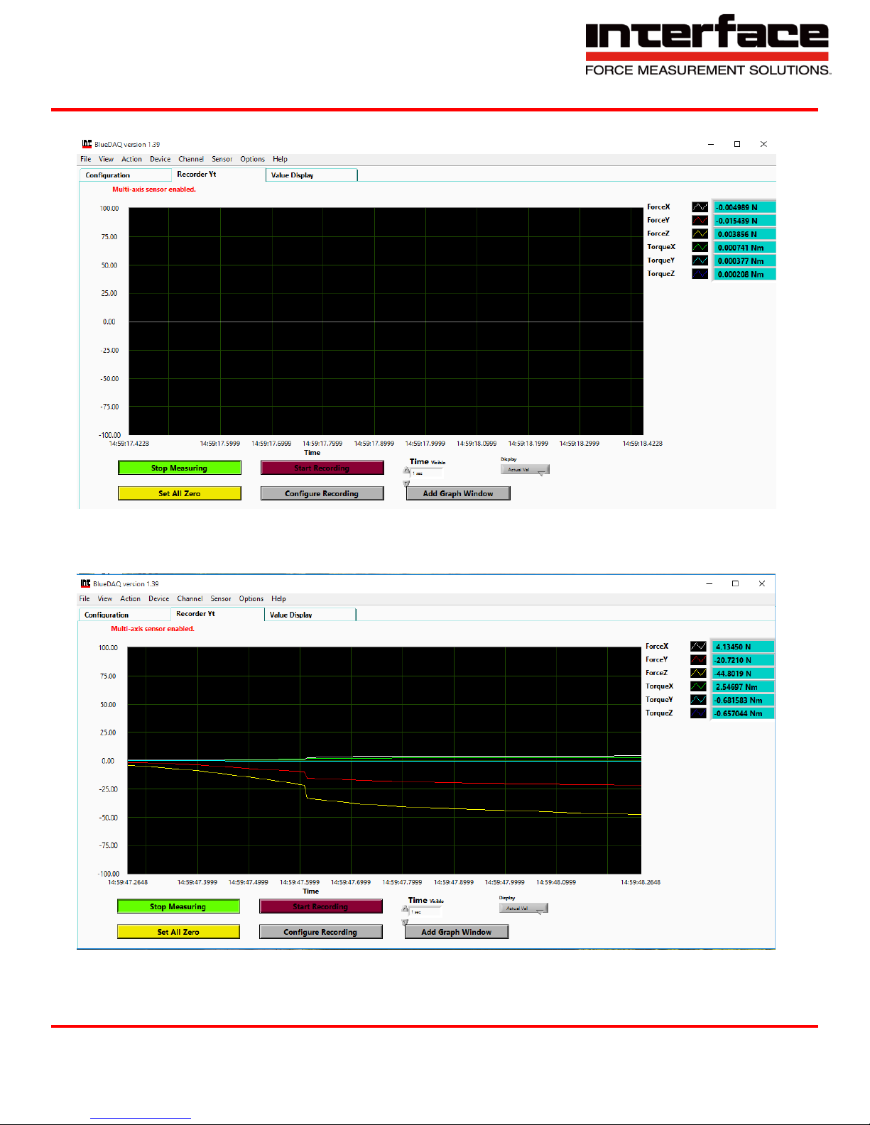
5. Recording Options are available.
FIGURE 17 - MEASUREMENT INITIATED
6. Recorder Tab, measurements of all Axis.
FIGURE 18 - VALUES MEASURED
Interface Inc. ● 7401 East Butherus Drive, Scottsdale, Arizona 85260 USA ● Phone 480.948.5555 ● Fax 480.948.1924
Document Number 15-216 Rev B Page 33 of 74
Page 34
9330 Operating Manual
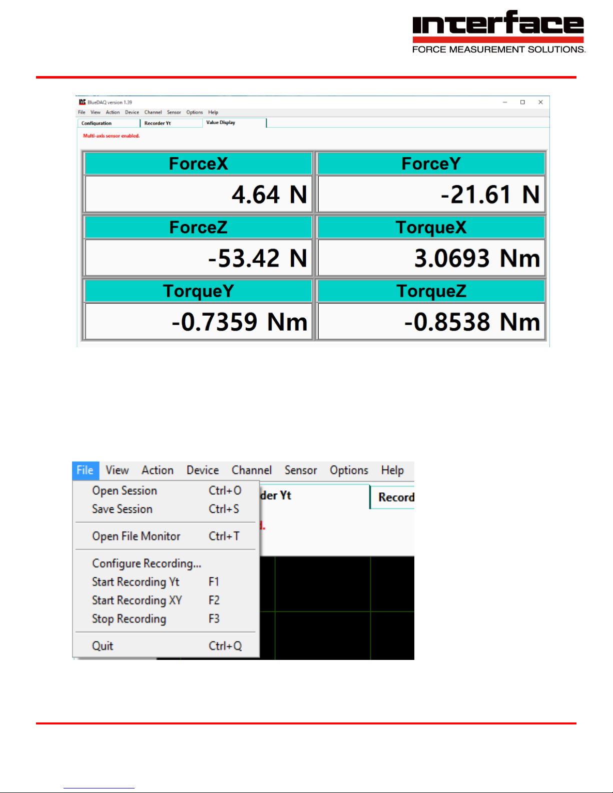
7. Value Display shows values in each Axis.
FIGURE 19 - VALUE DISPLAY SCREEN, EXAMPLE SHOWN FOR A 6-AXIS LOAD CELL
BlueDAQ Menus
File
Interface Inc. ● 7401 East Butherus Drive, Scottsdale, Arizona 85260 USA ● Phone 480.948.5555 ● Fax 480.948.1924
Document Number 15-216 Rev B Page 34 of 74
FIGURE 20 - FILE
Page 35
9330 Operating Manual
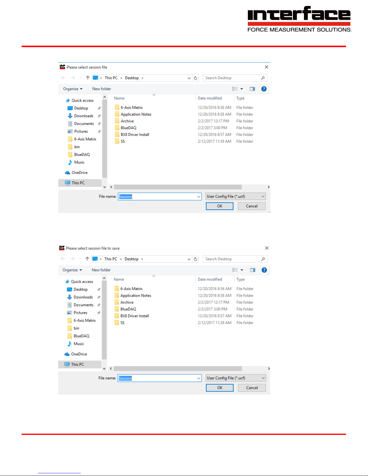
1. Open Session allows you to open a previous session and start where you left off.
FIGURE 21 - OPEN SESSION
2. Save Session allows you to save your session
FIGURE 22 - SAVE SESSION
Interface Inc. ● 7401 East Butherus Drive, Scottsdale, Arizona 85260 USA ● Phone 480.948.5555 ● Fax 480.948.1924
Document Number 15-216 Rev B Page 35 of 74
Page 36
9330 Operating Manual
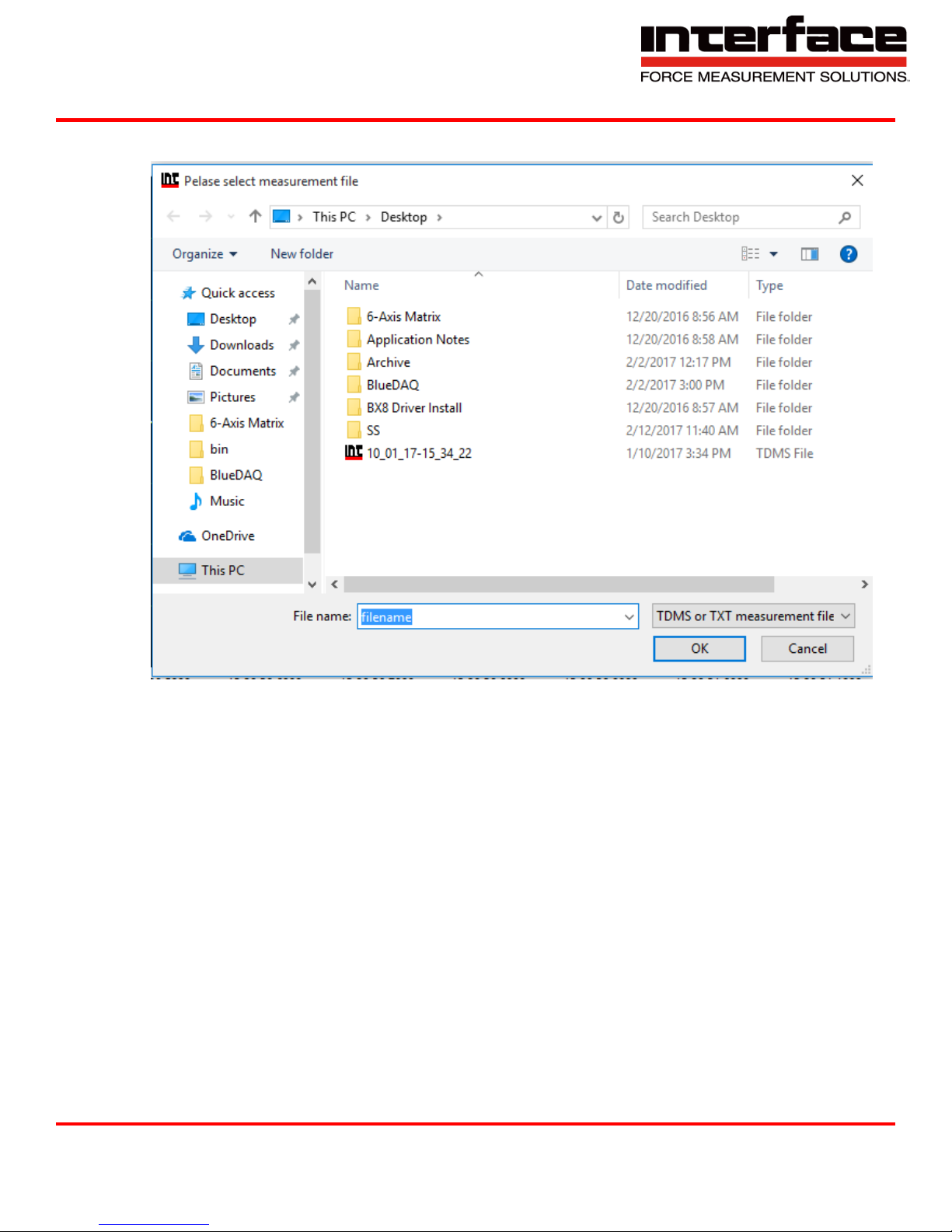
3. Open File Monitor allows you to open previous monitor file.
FIGURE 23 - OPEN FILE MONITOR
Interface Inc. ● 7401 East Butherus Drive, Scottsdale, Arizona 85260 USA ● Phone 480.948.5555 ● Fax 480.948.1924
Document Number 15-216 Rev B Page 36 of 74
Page 37
9330 Operating Manual
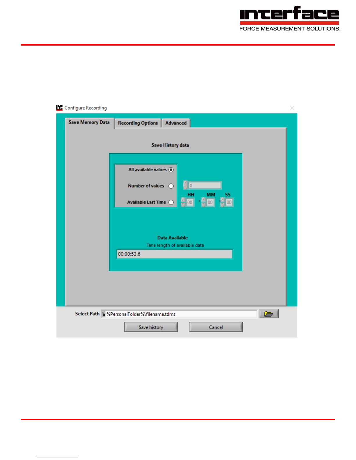
4. Configure Recording
4.1. Save Memory Data, allows you to save data of the recorded value.
A. All available values
B. Number of values
C. Available Last Time
D. Data Available
FIGURE 55 - SAVE MEMORY DATA
Interface Inc. ● 7401 East Butherus Drive, Scottsdale, Arizona 85260 USA ● Phone 480.948.5555 ● Fax 480.948.1924
Document Number 15-216 Rev B Page 37 of 74
Page 38
9330 Operating Manual
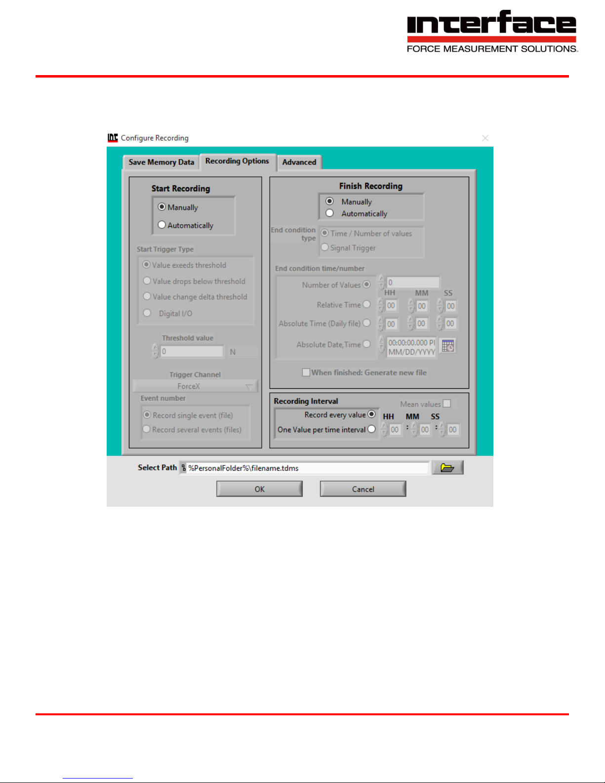
4.2. Recording Options
A. Manually allows you to choose the run and stop time of recording.
B. Automatically will choose the run and stop time.
FIGURE 24 - RECORDING OPTIONS
Interface Inc. ● 7401 East Butherus Drive, Scottsdale, Arizona 85260 USA ● Phone 480.948.5555 ● Fax 480.948.1924
Document Number 15-216 Rev B Page 38 of 74
Page 39
9330 Operating Manual
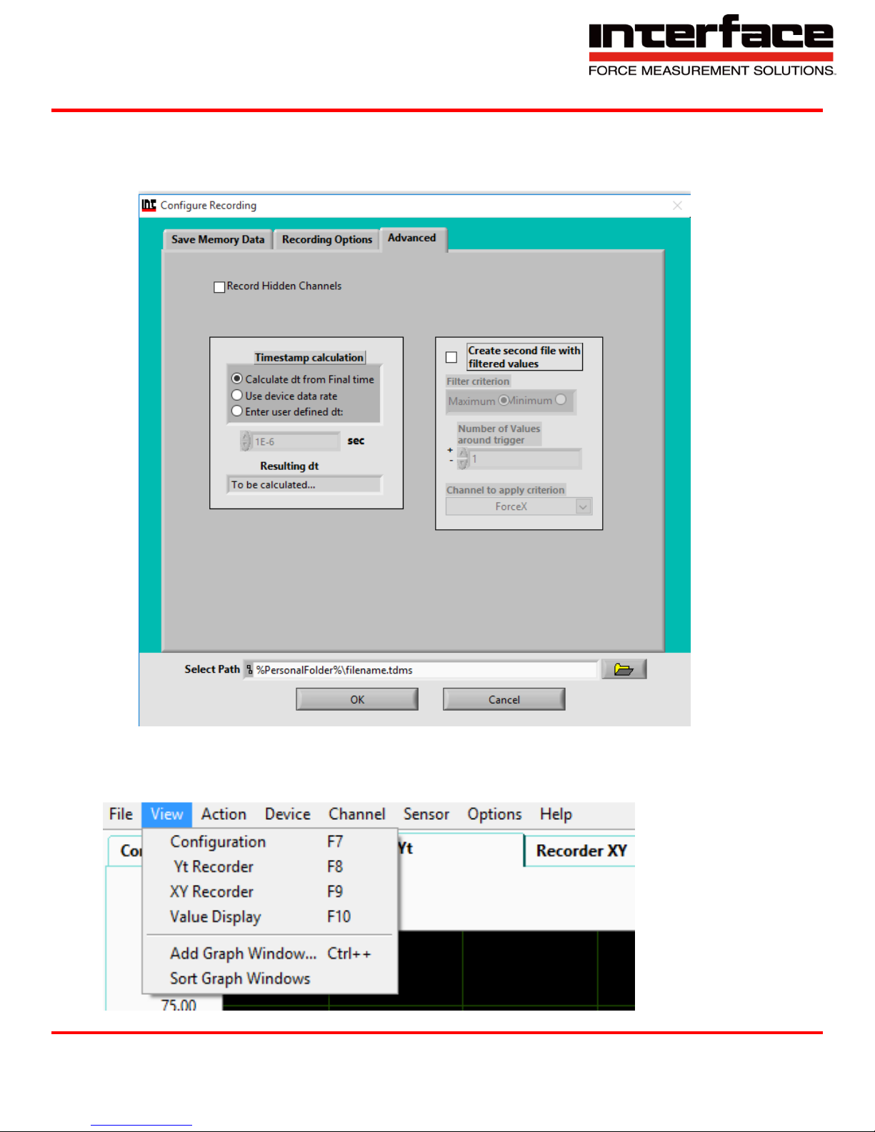
4.3. Advanced
A. Allows you to choose the timestamp, record hidden channels and create a second file
with filters.
FIGURE 25 - ADVANCED
View
Interface Inc. ● 7401 East Butherus Drive, Scottsdale, Arizona 85260 USA ● Phone 480.948.5555 ● Fax 480.948.1924
Document Number 15-216 Rev B Page 39 of 74
FIGURE 26 – VIEW
Page 40
9330 Operating Manual
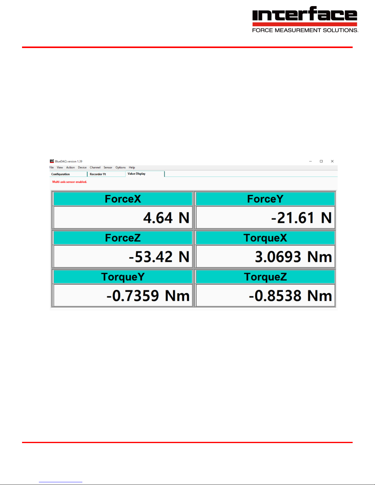
1. Configuration
1.1.1. Allows configurations of Axis to be viewed.
2. Yt Recorder
2.1. Shows only the Yt Axis
3. XY Recorder
3.1. Shows only the XY Axis
4. Value Display
4.1. Shows all Axis and values
FIGURE 27 - VALUE DISPLAY, EXAMPLE OF 6-AXIS LOAD CELL DISPLAY
Interface Inc. ● 7401 East Butherus Drive, Scottsdale, Arizona 85260 USA ● Phone 480.948.5555 ● Fax 480.948.1924
Document Number 15-216 Rev B Page 40 of 74
Page 41
9330 Operating Manual
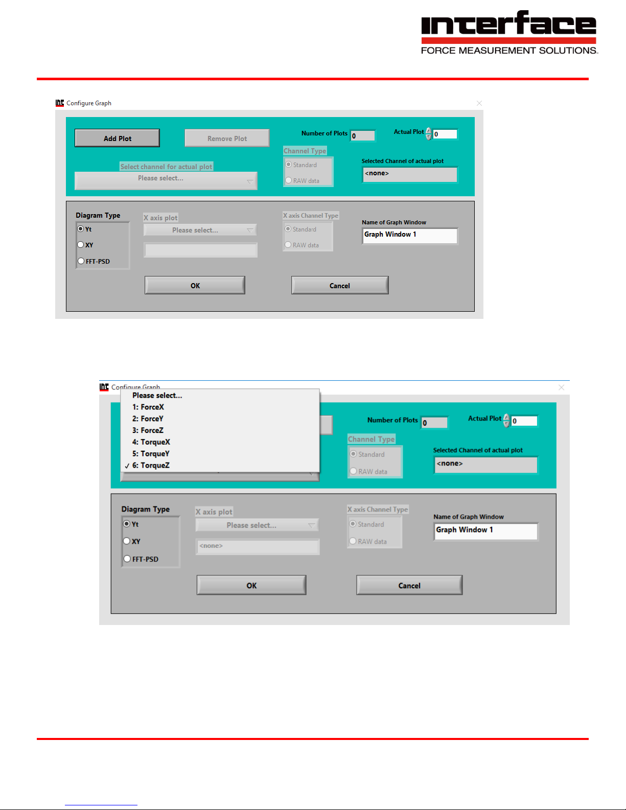
5. Add Graph Window
FIGURE 28 - ADD GRAPH WINDOW
5.1. Add Plot
A. Allows you to add an Axis to the graph.
FIGURE 29 - ADD PLOT
6. Sort Graph windows
6.1. Sort between graphs
Interface Inc. ● 7401 East Butherus Drive, Scottsdale, Arizona 85260 USA ● Phone 480.948.5555 ● Fax 480.948.1924
Document Number 15-216 Rev B Page 41 of 74
Page 42
9330 Operating Manual
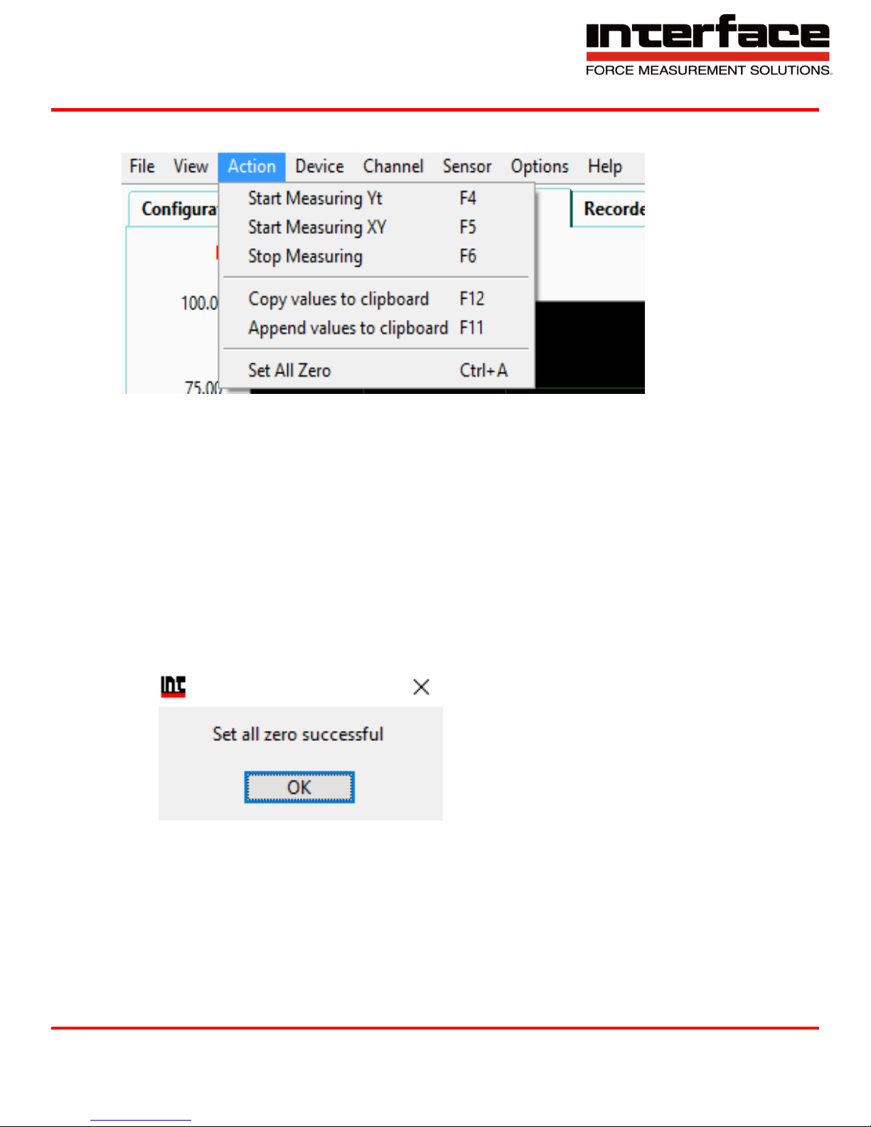
Action
FIGURE 30 - ACTION
1. Start Measuring Yt - Measures only the Yt axis.
2. Start Measuring XY - Measures only the XY Axis.
3. Stop Measuring - Stops measurement.
4. Copy Values to clipboard - Copies the last data measured.
5. Append values to clipboard - Add values to be copied.
6. Set All Zero - Sets all Values to Zero.
FIGURE 31 - SET ALL ZERO
Interface Inc. ● 7401 East Butherus Drive, Scottsdale, Arizona 85260 USA ● Phone 480.948.5555 ● Fax 480.948.1924
Document Number 15-216 Rev B Page 42 of 74
Page 43
9330 Operating Manual
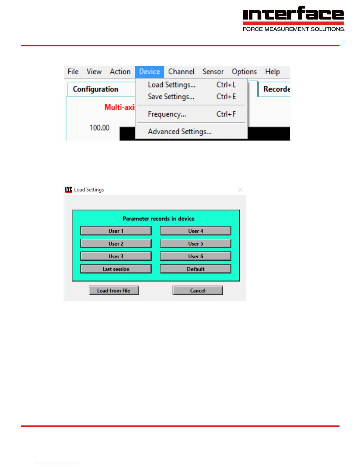
Device
FIGURE 32 – DEVICE
1. Load Settings
1.1. Load Settings from a Custom or Previous Setting
FIGURE 33 - LOAD SETTINGS
Interface Inc. ● 7401 East Butherus Drive, Scottsdale, Arizona 85260 USA ● Phone 480.948.5555 ● Fax 480.948.1924
Document Number 15-216 Rev B Page 43 of 74
Page 44
9330 Operating Manual
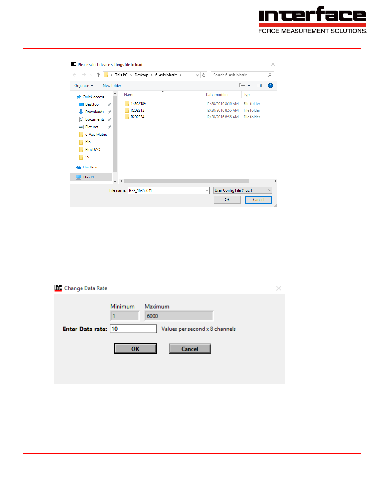
1.2. Load from File
FIGURE 34 - LOAD FROM FILE
2. Save Settings - Save current settings.
3. Frequency - Frequency rate of each record value per second.
3.1. Using low settings such as 1Hz or 0.1Hz may provide a stable reading, but slower refresh rate.
FIGURE 35 - FREQUENCY
Interface Inc. ● 7401 East Butherus Drive, Scottsdale, Arizona 85260 USA ● Phone 480.948.5555 ● Fax 480.948.1924
Document Number 15-216 Rev B Page 44 of 74
Page 45
9330 Operating Manual
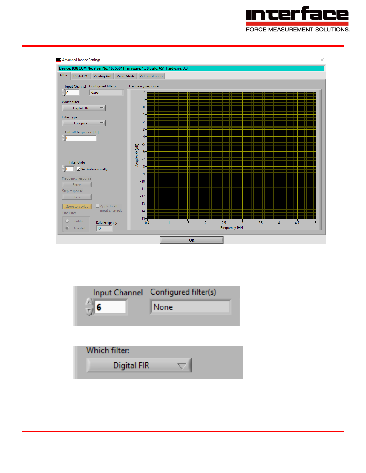
4. Advanced Settings
4.1. Filter
FIGURE 36 - FILTER
4.1.1. Input Channel – Digital Filters are individually configurable for each of the 8 analog input
channels. Select input channel here. Do this first, if the filter is not yet configured.
FIGURE 37 - INPUT CHANNEL
4.1.2. Which Filter
FIGURE 38 - WHICH FILTER
Interface Inc. ● 7401 East Butherus Drive, Scottsdale, Arizona 85260 USA ● Phone 480.948.5555 ● Fax 480.948.1924
Document Number 15-216 Rev B Page 45 of 74
Page 46
9330 Operating Manual
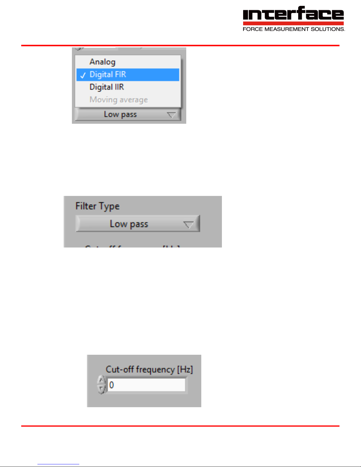
FIGURE 39 - FILTERS
A. Analog is the frontend low-pass filter
B. FIR is a Finite-Impulse-Response digital Low pass filter
C. IIR is an Infinite-Impulse-Response digital filter with selectable type.
4.1.3. Filter Type – Can only set if “Which filter” is set to IIR.
FIGURE 40 - FILTER TYPE
A. Low Pass frequencies above Cut-off are damped.
B. High Pass, frequencies below Cut-off are damped.
C. Band Pass, frequencies below Lower Cut-off and above Upper Cut-off are damped.
D. Band Stop, frequencies between Lower and Upper Cut-off are damped.
4.1.4. Cut-off frequency (Hz)
A. Cut-off frequency in Hz, where the signal is damped by -3dB. Lower Cut-off with Band
pass and Band stop type.
FIGURE 41 - CUT OFF FREQUENCY
Interface Inc. ● 7401 East Butherus Drive, Scottsdale, Arizona 85260 USA ● Phone 480.948.5555 ● Fax 480.948.1924
Document Number 15-216 Rev B Page 46 of 74
Page 47
9330 Operating Manual
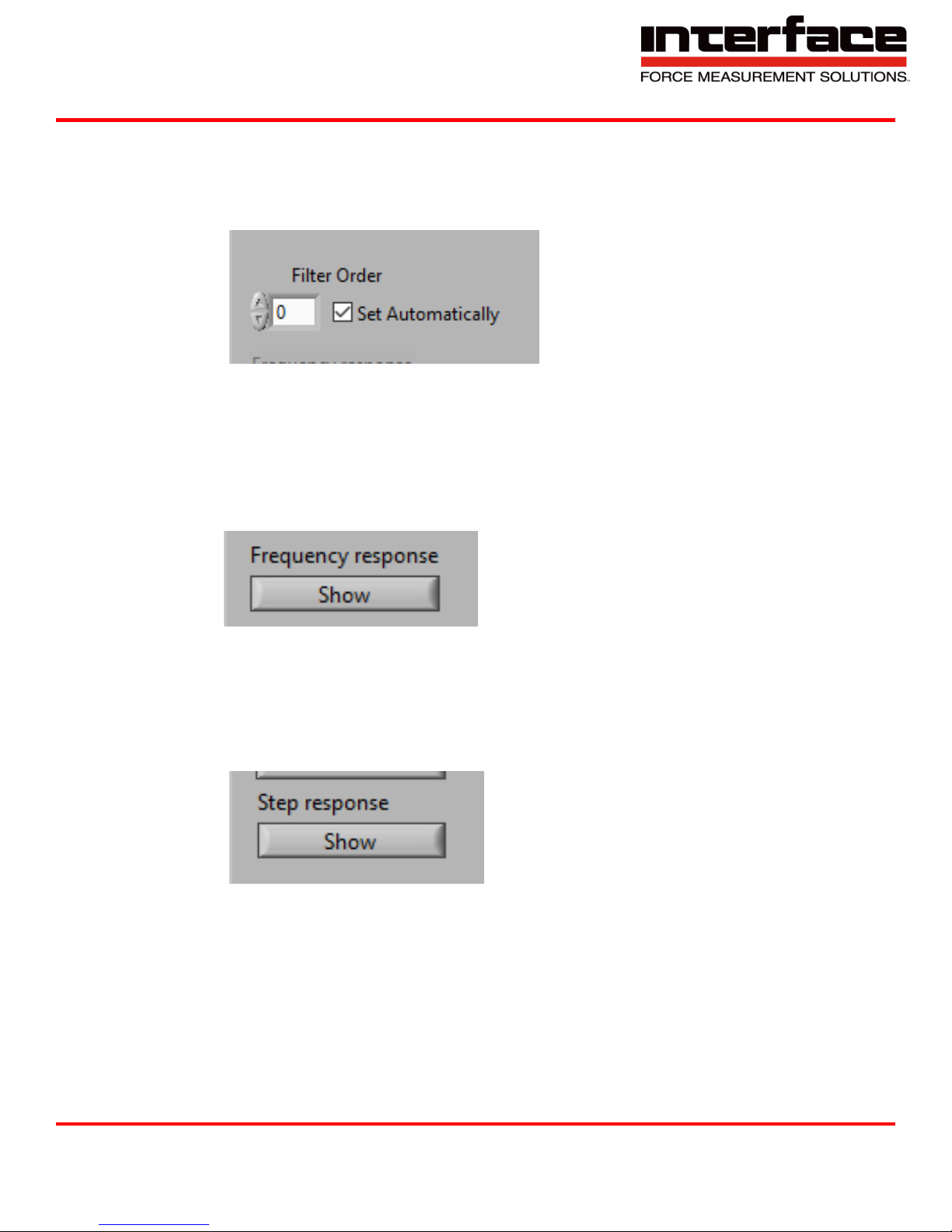
4.1.5. Filter Order
A. Settable for FIR Filter only
B. Higher order leads to steeper damping characteristics, but slower step response.
C. Lower cut-off frequency is possible with higher order, higher cut-off with lower order.
FIGURE 42 - FILTER ORDER
4.1.6. Frequency response
A. Calculate filter and show results in frequency domain of sine waves at the input of
different frequencies if successful.
B. Especially with IIR High pass. Band pass and Band stop, observe the graph carefully for
instability: A stable freq. response of an IIR filter is generally continuous and should
never exceed 0dB.
FIGURE 43 - FREQUENCY RESPONSE
4.1.7. Step response
A. Show filter output signal in time domain of standard step from 0 to nominal value at the
input at time=0.
B. Useful for determining settling time, e.g. for high-order FIR filter.
FIGURE 44 - STEP RESPONSE
Interface Inc. ● 7401 East Butherus Drive, Scottsdale, Arizona 85260 USA ● Phone 480.948.5555 ● Fax 480.948.1924
Document Number 15-216 Rev B Page 47 of 74
Page 48
9330 Operating Manual
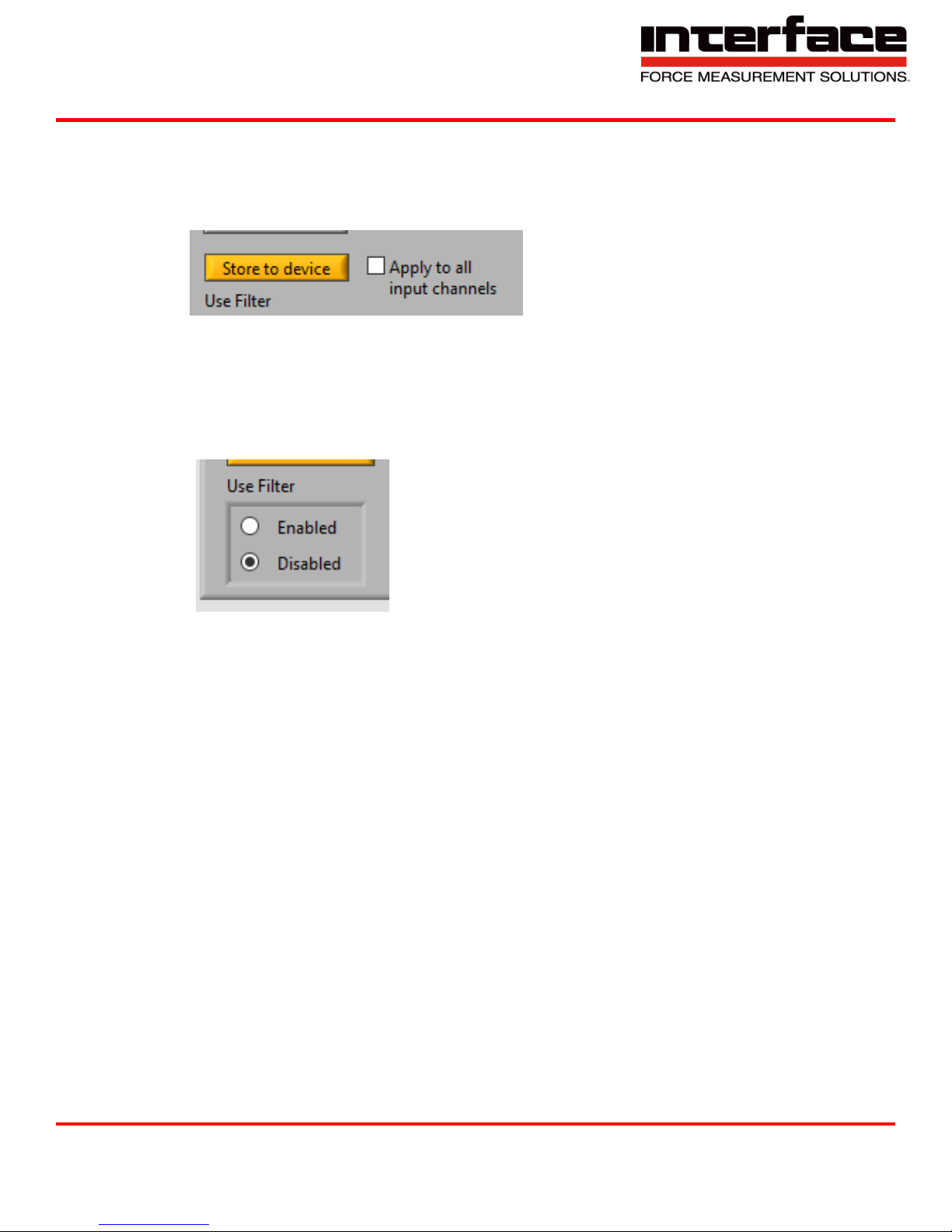
4.1.8. Store to device
A. Calculate filter and store all necessary information in the device if the calculation is
successful. The same settings will be stored for all 8 inputs if “Apply to all input
channels” is checked.
FIGURE 45 – STORE TO DEVICE
4.1.9. Use Filter
A. Enable or disable this filter. Even if disabled, all other filter settings will remain stored in
device (if no error occurred), if they are already stored.
B. This filter will be enabled/disabled for all 8 inputs channels if “Apply to all channels” is
checked.
FIGURE 46 - USE FILTER
Interface Inc. ● 7401 East Butherus Drive, Scottsdale, Arizona 85260 USA ● Phone 480.948.5555 ● Fax 480.948.1924
Document Number 15-216 Rev B Page 48 of 74
Page 49
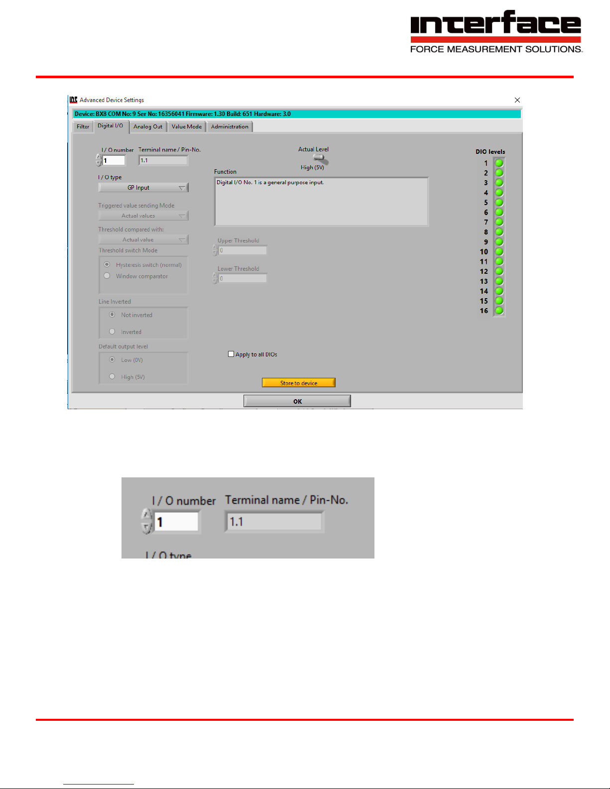
4.2. Digital I/O
9330 Operating Manual
FIGURE 47 - DIGITAL I/O
4.3. I/O number
4.3.1. Devices can have up to 16 digital I/O lines. Enter number of digital I/O here.
FIGURE 48 - I/O NUMBER
4.3.2. I/O type
A. GP Input – “General Purpose” Input
B. Tare Single – Zero out.
C. Tare All – Zero all.
D. Reset Max/Min
Interface Inc. ● 7401 East Butherus Drive, Scottsdale, Arizona 85260 USA ● Phone 480.948.5555 ● Fax 480.948.1924
Document Number 15-216 Rev B Page 49 of 74
Page 50

9330 Operating Manual
E. Trigger Send value
i. Actual Values
ii. Maximum Values
iii. Minimum Values
iv. Mean Values
F. GP Output – “General Purpose” Output
G. Threshold Switch
4.3.3. Threshold switch Mode – Only Activated if Threshold Switch is selected in I/O type.
A. Hysteresis switch (normal) – Digital output becomes active if measuring value of
corresponding channel is above ON-threshold. It becomes inactive if measuring value of
corresponding channel is blow OFF-threshold.
B. Window comparator – Digital output becomes active if measuring value of corresponding
channel is between upper and lower threshold, otherwise inactive.
4.3.4. Line Inverted
A. Not inverted – Active level is logical high = 5V. Inactive logical low is 0V.
B. Inverted – Active level is logical low – 0V. Inactive logical high is 5V.
4.3.5. Default output level – Level which digital I/O will output by default. That applies to all
DIO output types after power-on, before a set output condition occurs.
A. E.g. set output level command if GP output type.
Interface Inc. ● 7401 East Butherus Drive, Scottsdale, Arizona 85260 USA ● Phone 480.948.5555 ● Fax 480.948.1924
Document Number 15-216 Rev B Page 50 of 74
Page 51
9330 Operating Manual
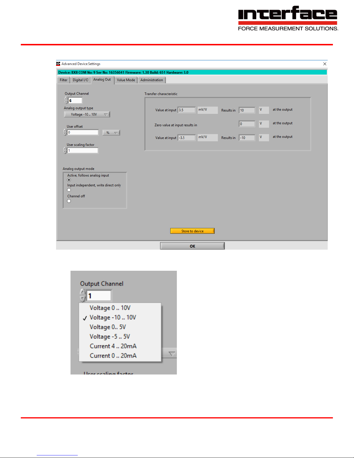
4.4. Analog Out
FIGURE 49 - ANALOG OUT
4.4.1. Output Channel – Analog output type, voltage or current.
FIGURE 50 - OUTPUT CHANNEL
Interface Inc. ● 7401 East Butherus Drive, Scottsdale, Arizona 85260 USA ● Phone 480.948.5555 ● Fax 480.948.1924
Document Number 15-216 Rev B Page 51 of 74
Page 52
9330 Operating Manual
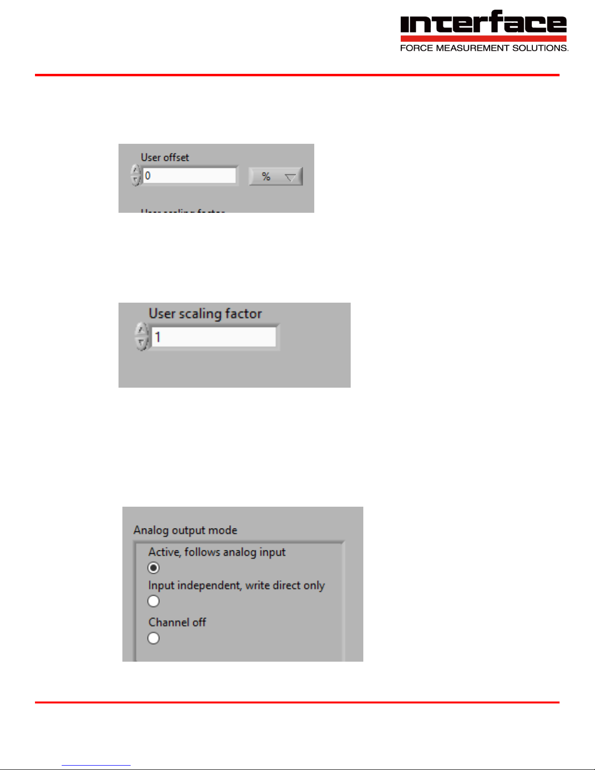
4.4.2. User offset – Additional offset in percent, which defines output value at zero analog
input value.
A. E.g. if set to 50%, analog out value will be half of the positive range.
B. 2.5V at 0-5V or ±5V.
FIGURE 51 - USER OFFSET
4.4.3. User scaling factor – Scaling factor to adapt analog input physical values to analog
output.
A. If using User offset, set User offset first, then User scaling.
FIGURE 52 - USER SCALING FACTOR
4.4.4. Analog output mode
A. Active, follows analog input – Output value depends on setting and analog input value of
the same input channel number.
B. Input independent, write direct only – Use analog output DAC directly.
C. Channel off – Channel switch is off.
FIGURE 53 - ANALOG OUTPUT MODE
Interface Inc. ● 7401 East Butherus Drive, Scottsdale, Arizona 85260 USA ● Phone 480.948.5555 ● Fax 480.948.1924
Document Number 15-216 Rev B Page 52 of 74
Page 53
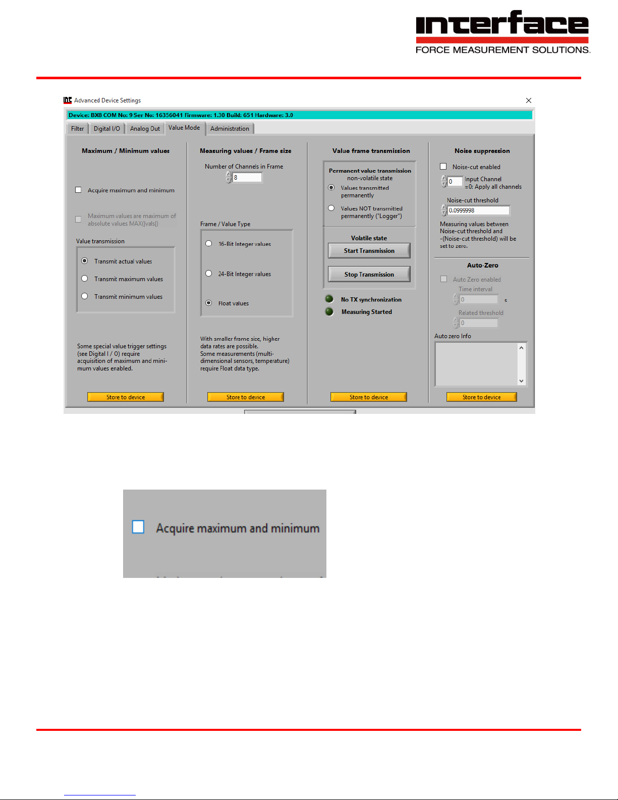
4.5. Value Mode
9330 Operating Manual
FIGURE 54 - VALUE MODE
4.5.1. Acquire maximum and minimum – Max/Min value determination enabled. This is a
precondition for other max/min settings, also for some threshold and value-trigger modes.
FIGURE 55 - ACQUIRE MAX AND MIN
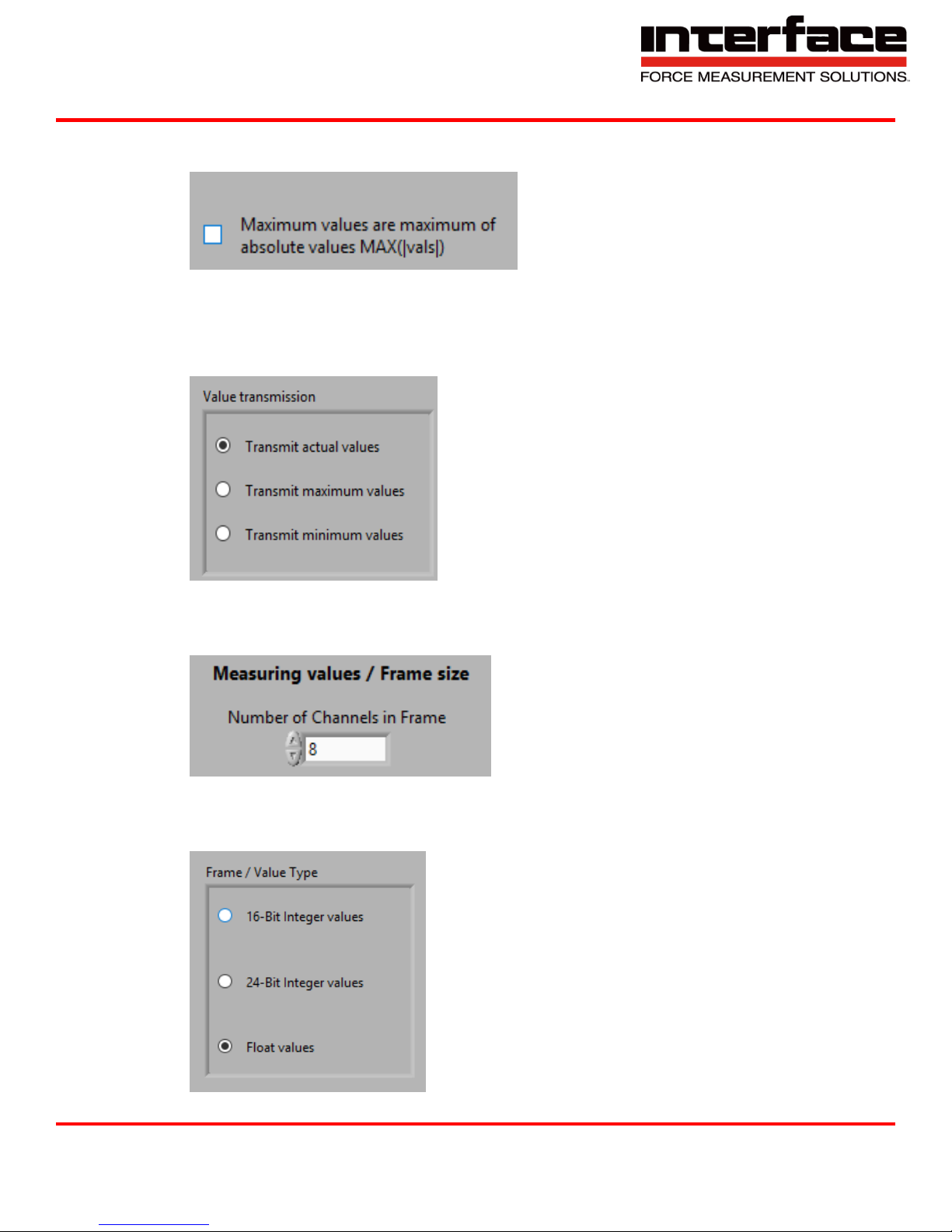
4.5.2. Maximum values are maximum of absolute values MAX(|vals|) – Only active if “Acquire
maximum and minimum” is checked. Replaces the maximum value register with that
Interface Inc. ● 7401 East Butherus Drive, Scottsdale, Arizona 85260 USA ● Phone 480.948.5555 ● Fax 480.948.1924
Document Number 15-216 Rev B Page 53 of 74
Page 54
9330 Operating Manual
maximum of the absolute values, so that both positive maximum and negative maximum
values are determined.
FIGURE 56 - MAX VALUES ARE MAXIMUM OF ABSOLUTE VALUES
4.5.3. Value transmission – Which values are in the value frame: All channels are either actual
values, maximum values or minimum values.
FIGURE 57 - VALUE TRANSMISSION
4.5.4. Number of Channels in Frame – Number of input channel values in the measuring data
frame. With smaller numbers, higher data frequencies are possible.
FIGURE 58 - MEASURING VALUES / FRAME SIZE
4.5.5. Frame / Value Type – Data type of measuring values in the value-frame that device
transmits.
Interface Inc. ● 7401 East Butherus Drive, Scottsdale, Arizona 85260 USA ● Phone 480.948.5555 ● Fax 480.948.1924
Document Number 15-216 Rev B Page 54 of 74
FIGURE 59 - FRAME / VALUE TYPE
Page 55
9330 Operating Manual
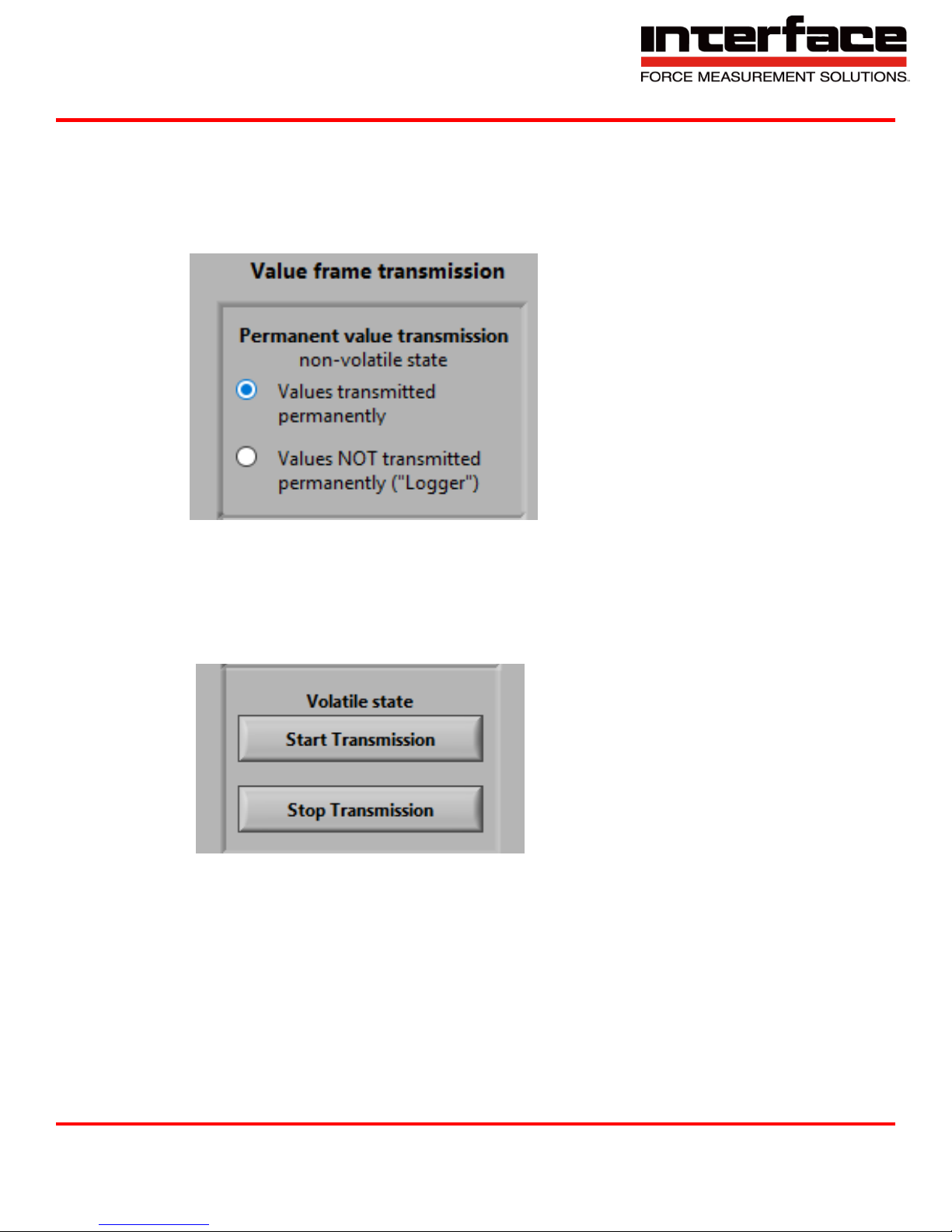
4.5.6. Value frame transmission
A. Values transmitted permanently – After power-on, the device transmits measuring values
continuously.
B. Values NOT transmitted permanently – After power-on, the device transmits measuring
values on request.
FIGURE 60 - VALUE FRAME TRANSMISSION
4.5.7. Volatile state
A. Start transmission of measuring values, if permanent value transmission is off. State not
stored in non-volatile memory.
B. Stop Transmission of measuring values, if permanent value transmission is on. State not
stored in non-volatile memory.
FIGURE 61 - VOLATILE STATE
Interface Inc. ● 7401 East Butherus Drive, Scottsdale, Arizona 85260 USA ● Phone 480.948.5555 ● Fax 480.948.1924
Document Number 15-216 Rev B Page 55 of 74
Page 56
9330 Operating Manual
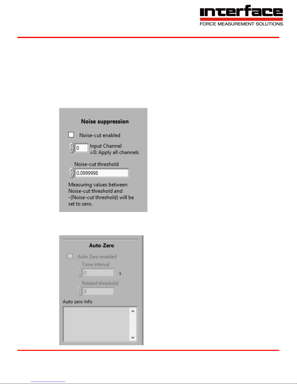
4.5.8. Noise suppression
A. Noise-cut enabled – If measuring values are between Noise-cut threshold and (Noise-cut
threshold), they will be set to 0.000000000, so that the noise around zero will be
suppressed. Set checkbox to enable this feature.
B. Input Channel = 0: Apply all channels – Input channel to be used with Noise-cut. Set to
0: Use the same threshold for all inputs.
C. Noise-cut threshold – If measuring values are between Noise-cut threshold and (Noise-
cut threshold), they will be set to 0.000000000, so that the noise around zero will be
suppressed.
FIGURE 62 - NOISE SUPPRESSION
4.5.9. Auto-Zero enabled – Every (Time interval) seconds, an automatic set-zero routine will
be performed.
FIGURE 63 - AUTO-ZERO
Interface Inc. ● 7401 East Butherus Drive, Scottsdale, Arizona 85260 USA ● Phone 480.948.5555 ● Fax 480.948.1924
Document Number 15-216 Rev B Page 56 of 74
Page 57
9330 Operating Manual
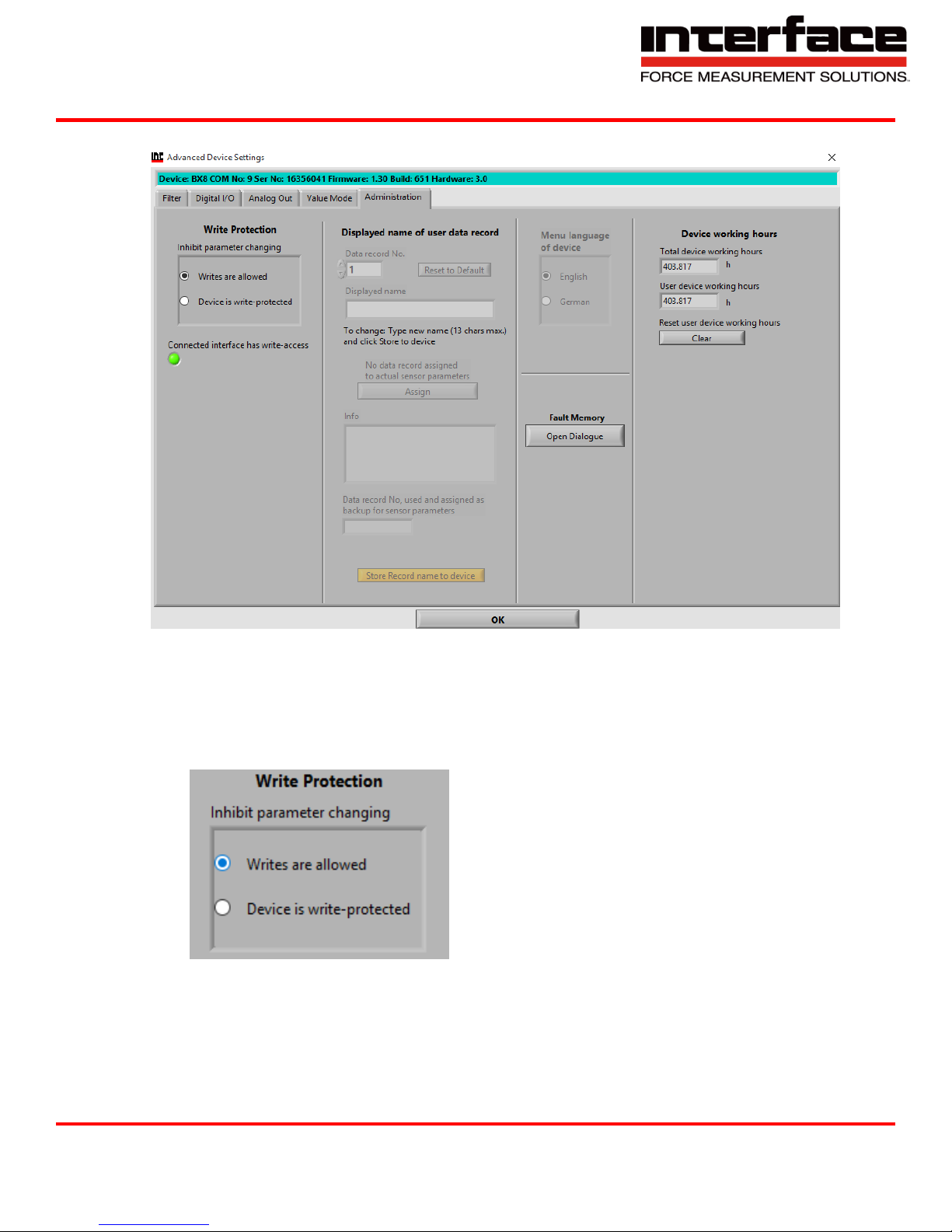
4.6. Administration
FIGURE 64 - ADMINISTRATION
4.6.1. Write Protection
A. Inhibit parameter changing – If the device is write-protected, the device parameters are
secured from unintentional changing. To disable write-protection, a device-depended
password must be entered.
FIGURE 65 - WRITE PROTECTION
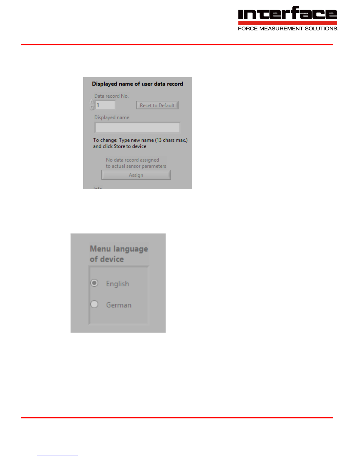
4.7. Displayed name of user data record
4.7.1. Data record No. – Six different parameter records can be saved and restored; in the
main window with “Save Settings” and “Load Settings”. User-defined names for each data
Interface Inc. ● 7401 East Butherus Drive, Scottsdale, Arizona 85260 USA ● Phone 480.948.5555 ● Fax 480.948.1924
Document Number 15-216 Rev B Page 57 of 74
Page 58
9330 Operating Manual
record can be viewed and changed here. Parameter record number (1 to 6) can be set by
this, to view and change its name.
A. Displayed name – Name of the parameter record.
FIGURE 66 - DISPLAYED NAME OF USER DATA
RECORD
4.7.2. Menu language of device
A. English
B. German
FIGURE 67 - MENU LANGUAGE OF DEVICE
Interface Inc. ● 7401 East Butherus Drive, Scottsdale, Arizona 85260 USA ● Phone 480.948.5555 ● Fax 480.948.1924
Document Number 15-216 Rev B Page 58 of 74
Page 59
9330 Operating Manual
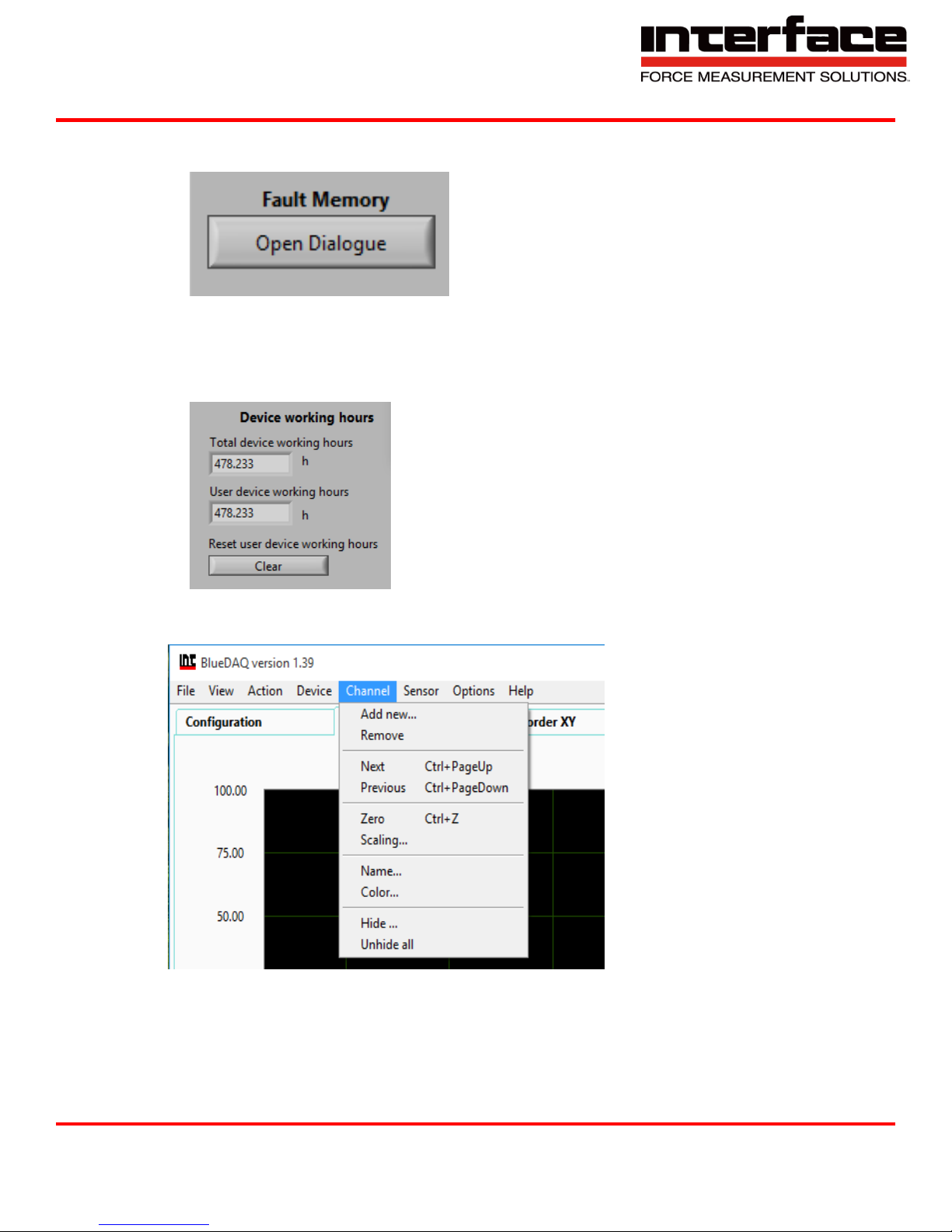
4.7.3. Fault memory – Some devices are capable of storing faults that are related to external
connections. E.g. broken sensor cable or value saturated.
FIGURE 68 - FAULT MEMORY
4.7.4. Device working hours – Some devices count their working hours. This displays the
absolute working hours, which can’t be reset.
Channel
FIGURE 69 - DEVICE WORKING HOURS
FIGURE 70 - CHANNEL
Interface Inc. ● 7401 East Butherus Drive, Scottsdale, Arizona 85260 USA ● Phone 480.948.5555 ● Fax 480.948.1924
Document Number 15-216 Rev B Page 59 of 74
Page 60
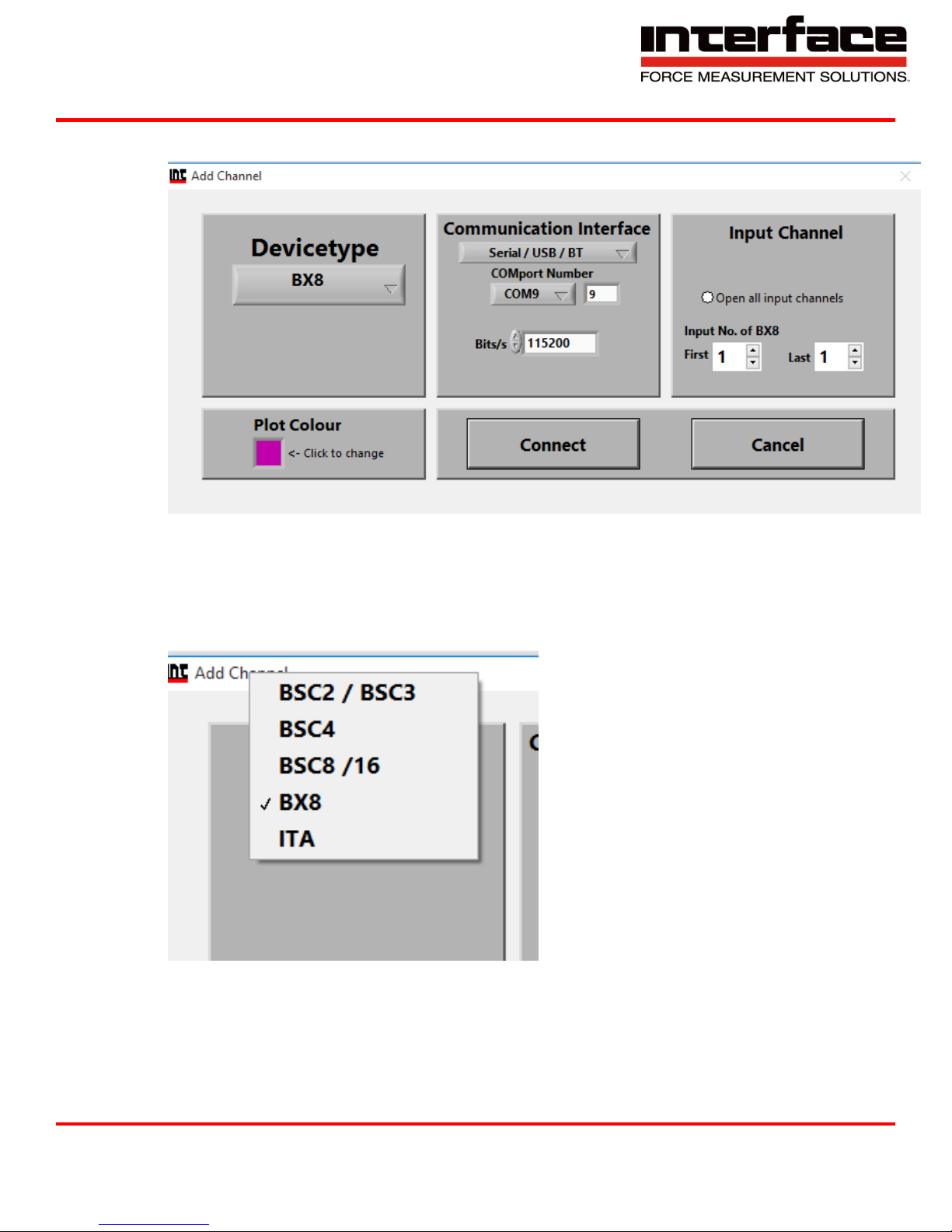
1. Add new
FIGURE 71 - ADD NEW
9330 Operating Manual
1.1. Devicetype
FIGURE 72 – DEVICETYPE
Interface Inc. ● 7401 East Butherus Drive, Scottsdale, Arizona 85260 USA ● Phone 480.948.5555 ● Fax 480.948.1924
Document Number 15-216 Rev B Page 60 of 74
Page 61
9330 Operating Manual
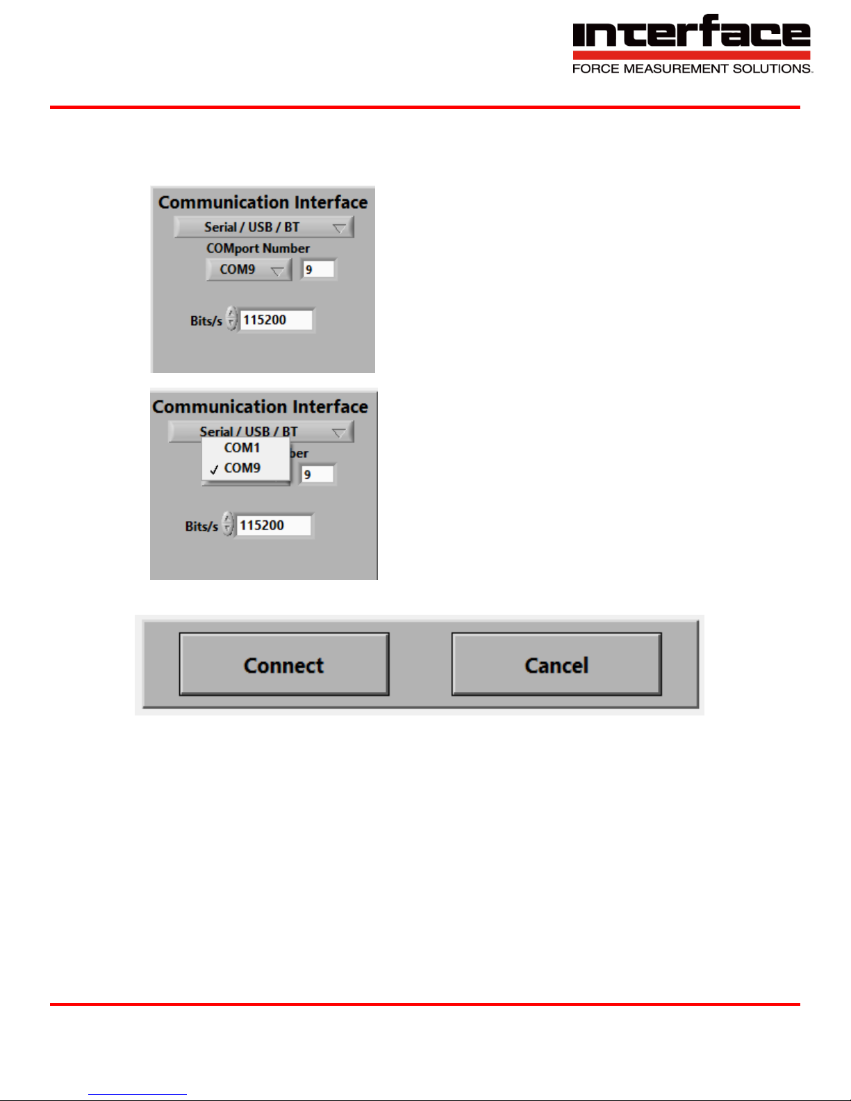
1.2. Communication Interface
1.2.1. Bits/s – Communication Bitrate. If you aren’t sure which Bitrate is appropriate to your
device, leave this at 115200.
FIGURE 73 - COMMUNICATION INTERFACE
1.3. Connect and Cancel
FIGURE 75 - CONNECT AND CANCEL
FIGURE 74 - COMMUNICATION INTERFACE COM
Interface Inc. ● 7401 East Butherus Drive, Scottsdale, Arizona 85260 USA ● Phone 480.948.5555 ● Fax 480.948.1924
Document Number 15-216 Rev B Page 61 of 74
Page 62
9330 Operating Manual
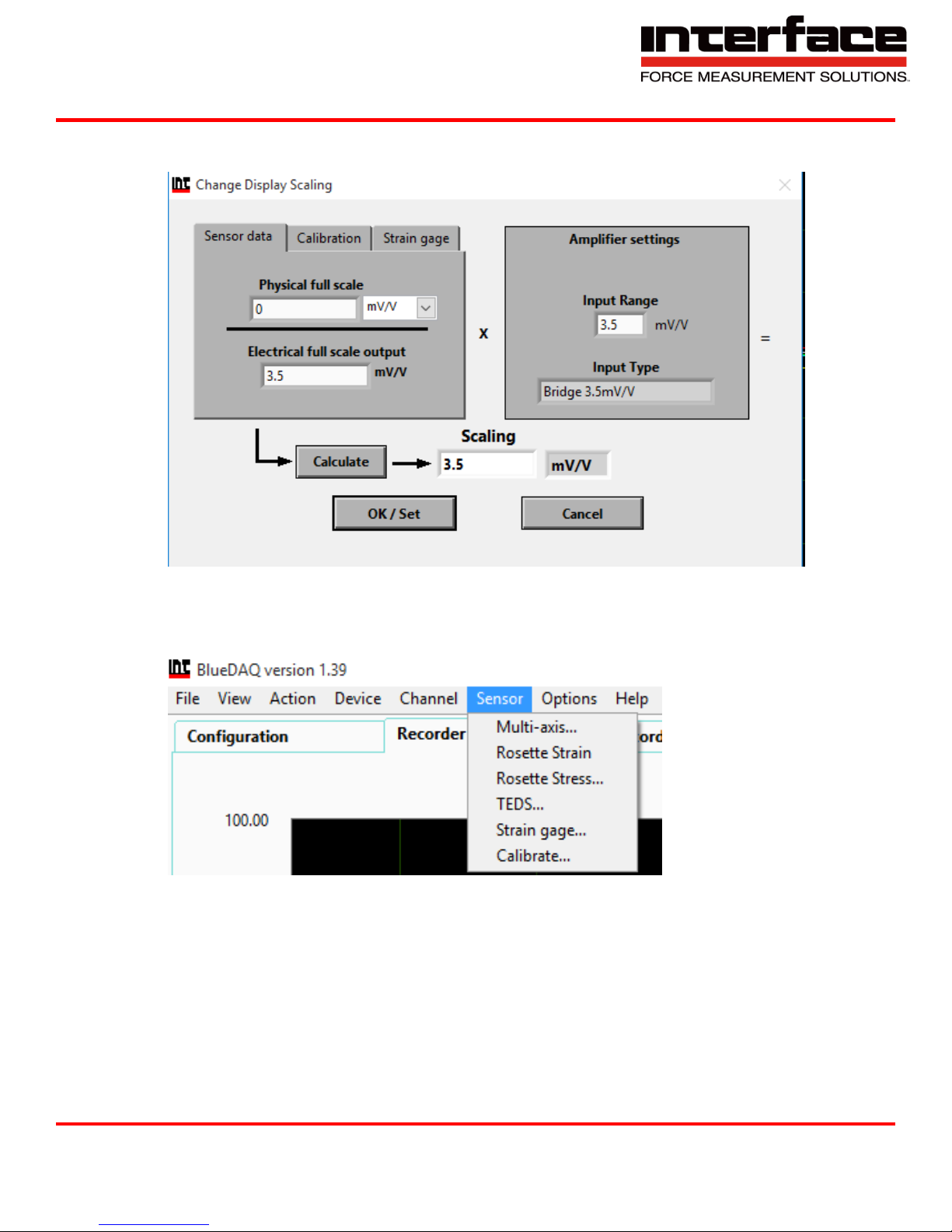
2. Channel Scaling
Sensor
FIGURE 76 - CHANNEL SCALING
FIGURE 77 – SENSOR MENU
Interface Inc. ● 7401 East Butherus Drive, Scottsdale, Arizona 85260 USA ● Phone 480.948.5555 ● Fax 480.948.1924
Document Number 15-216 Rev B Page 62 of 74
Page 63
9330 Operating Manual
1. Multi-axis – Refer to step 5.
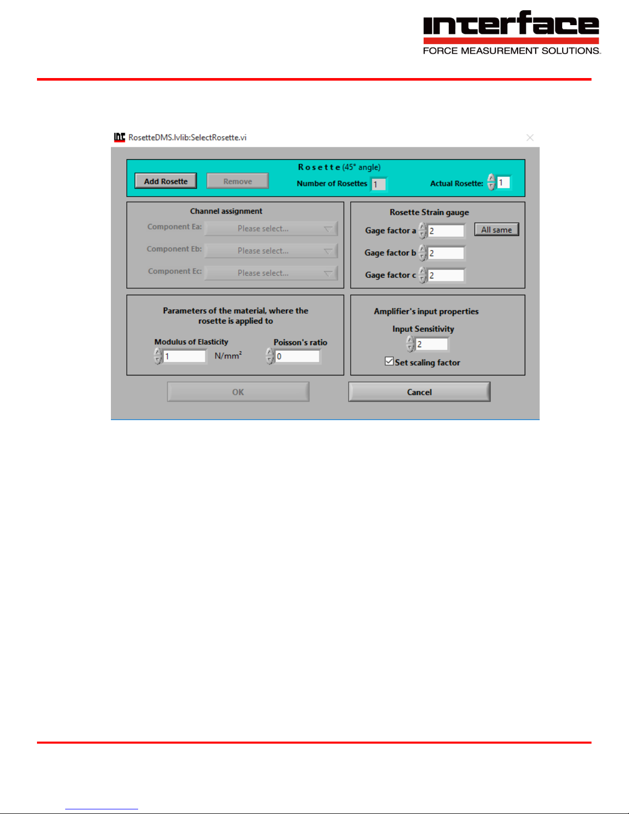
2. Rosette Strain – Arrangement of two or more strain gauges.
3. Rosette Stress
FIGURE 78 - ROSETTE STRESS
Interface Inc. ● 7401 East Butherus Drive, Scottsdale, Arizona 85260 USA ● Phone 480.948.5555 ● Fax 480.948.1924
Document Number 15-216 Rev B Page 63 of 74
Page 64
9330 Operating Manual
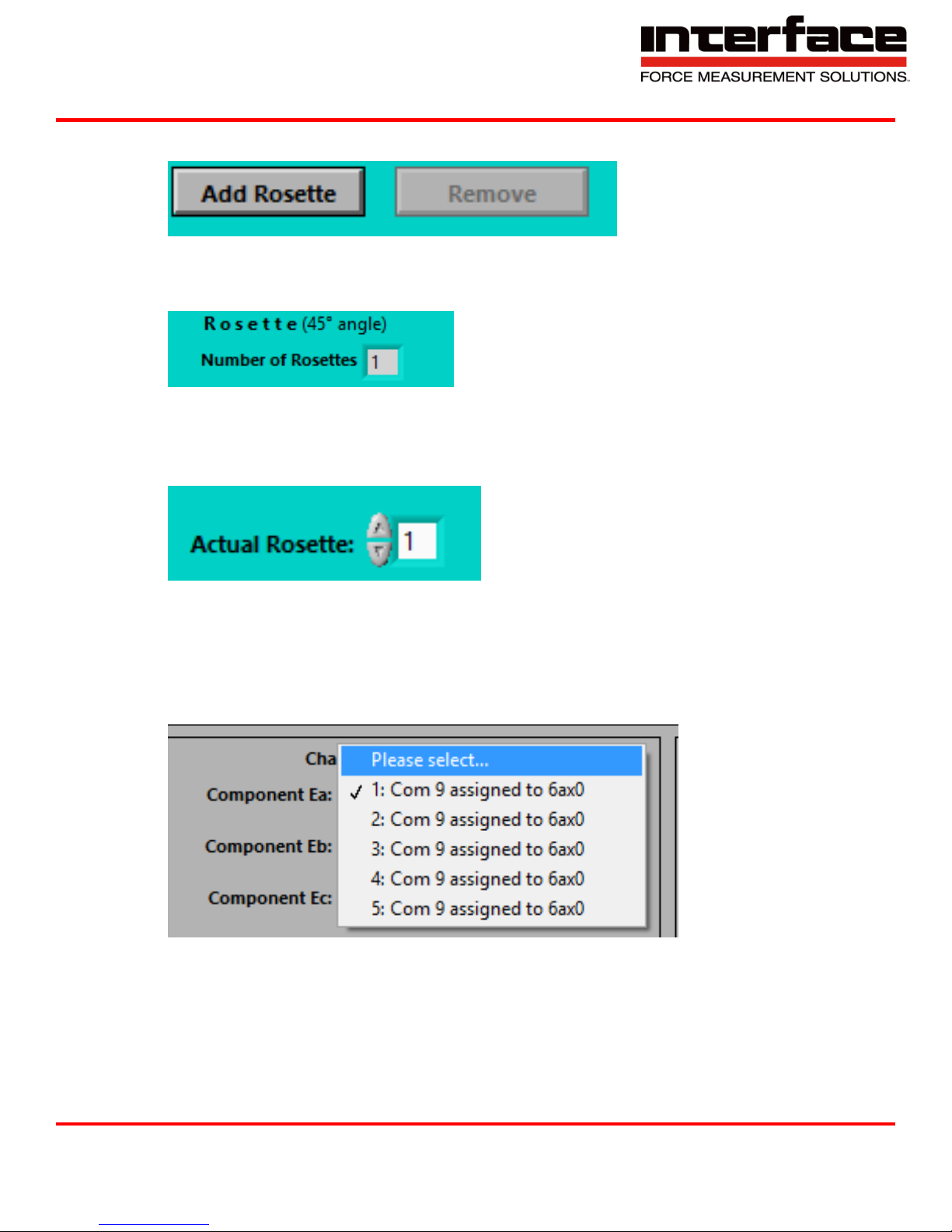
4. Add Rosette / Remove
FIGURE 79 - ADD ROSETTE
5. Number of Rosettes – Number of included rosette strain gauges which are configured already.
FIGURE 80 - NUMBER OF ROSETTES
6. Actual Rosette – If you have configured more than one rosette strain gauge, here you can switch
between the different rosette stain gauge settings.
FIGURE 81 - ACTUAL ROSETTE
7. Component Ea: - The Rosette-Strain gauge consists of three single strain gauges which are
arranged at an angle of 45° to each other. Choose here for the physical channel of your
measuring amplifier where the single strain gauge Epsilon A is connected to. The resulting angle
value of Phi refers to the longitudinal axis of this single strain gauge.
FIGURE 82 - COMPONENT EA
Interface Inc. ● 7401 East Butherus Drive, Scottsdale, Arizona 85260 USA ● Phone 480.948.5555 ● Fax 480.948.1924
Document Number 15-216 Rev B Page 64 of 74
Page 65
9330 Operating Manual
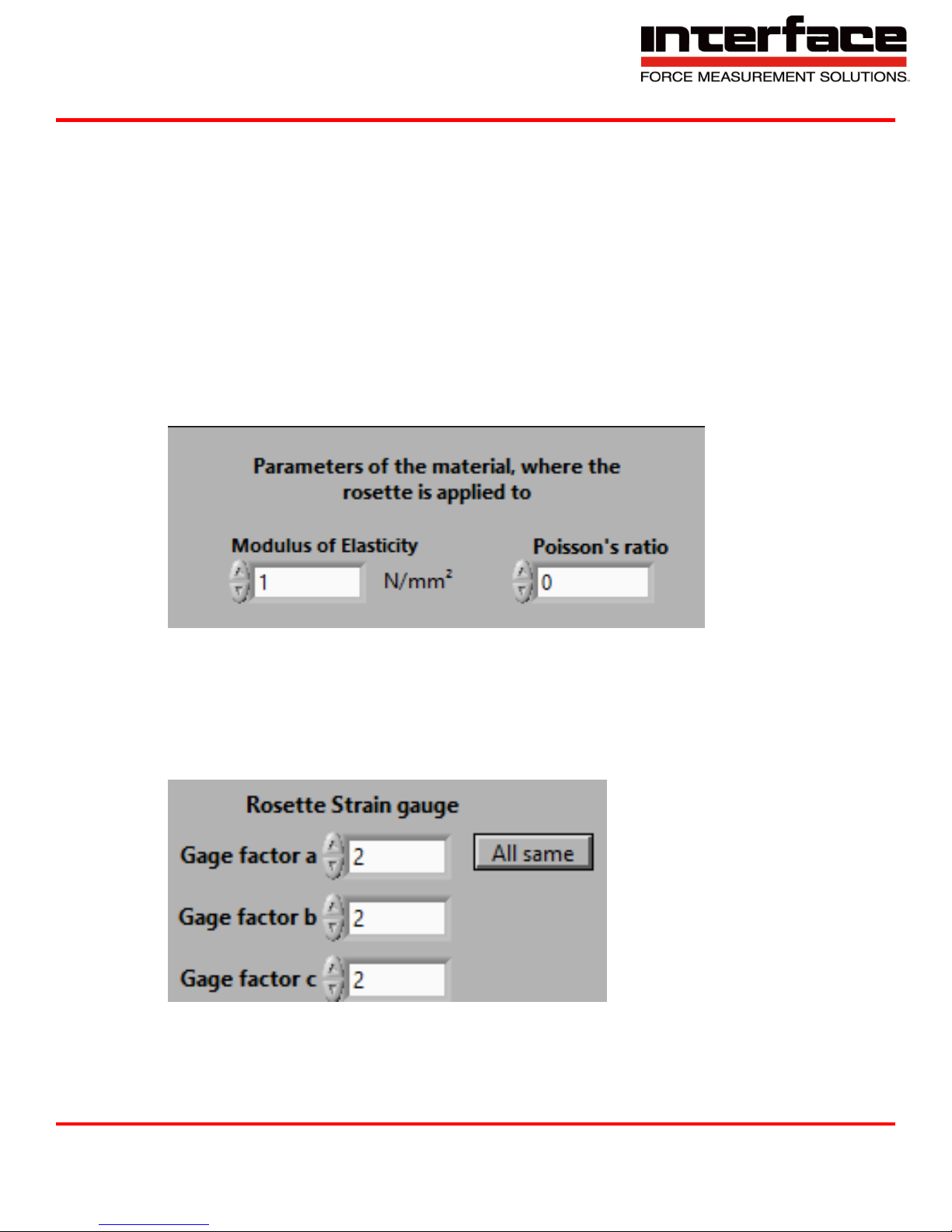
8. Parameters of the material, where the rosette is applied to
8.1. Modulus of Elasticity – Enter the elastic modulus of the material, whose stress shall be
determined in Newtown per square millimeters. The elastic modulus of an object is defined as
the slope of its stress-strain curve in the elastic deformation region of the material to be
measured. Since this parameter is very significant for the stress calculation, it should be entered
as exact as possible. Please multiply the values in lb/in2 with 0.0068971125763 to get the
modulus in N/mm2.
8.2. Poisson’s ratio – Enter the Poisson’s ratio of the material whose stress shall be determined. The
Poisson’s ratio is the ratio when a sample object is stretched of the contraction or transverse
strain (perpendicular to the applied load), to the extension or axial strain. Since this parameter is
a little less significant for the stress calculation, an approximate value may be entered.
FIGURE 83 - PARAMETERS OF THE MATERIAL
8.3. Gage factor – Enter the gage factor for the single strain gauge. The gauge factor is the ratio of
relative change in an electrical resistance to the mechanical strain epsilon. If all three gauge
factors are equal, enter the value and then press “All Same”.
FIGURE 84 - ROSETTE STRAIN GAUGE
Interface Inc. ● 7401 East Butherus Drive, Scottsdale, Arizona 85260 USA ● Phone 480.948.5555 ● Fax 480.948.1924
Document Number 15-216 Rev B Page 65 of 74
Page 66
9330 Operating Manual
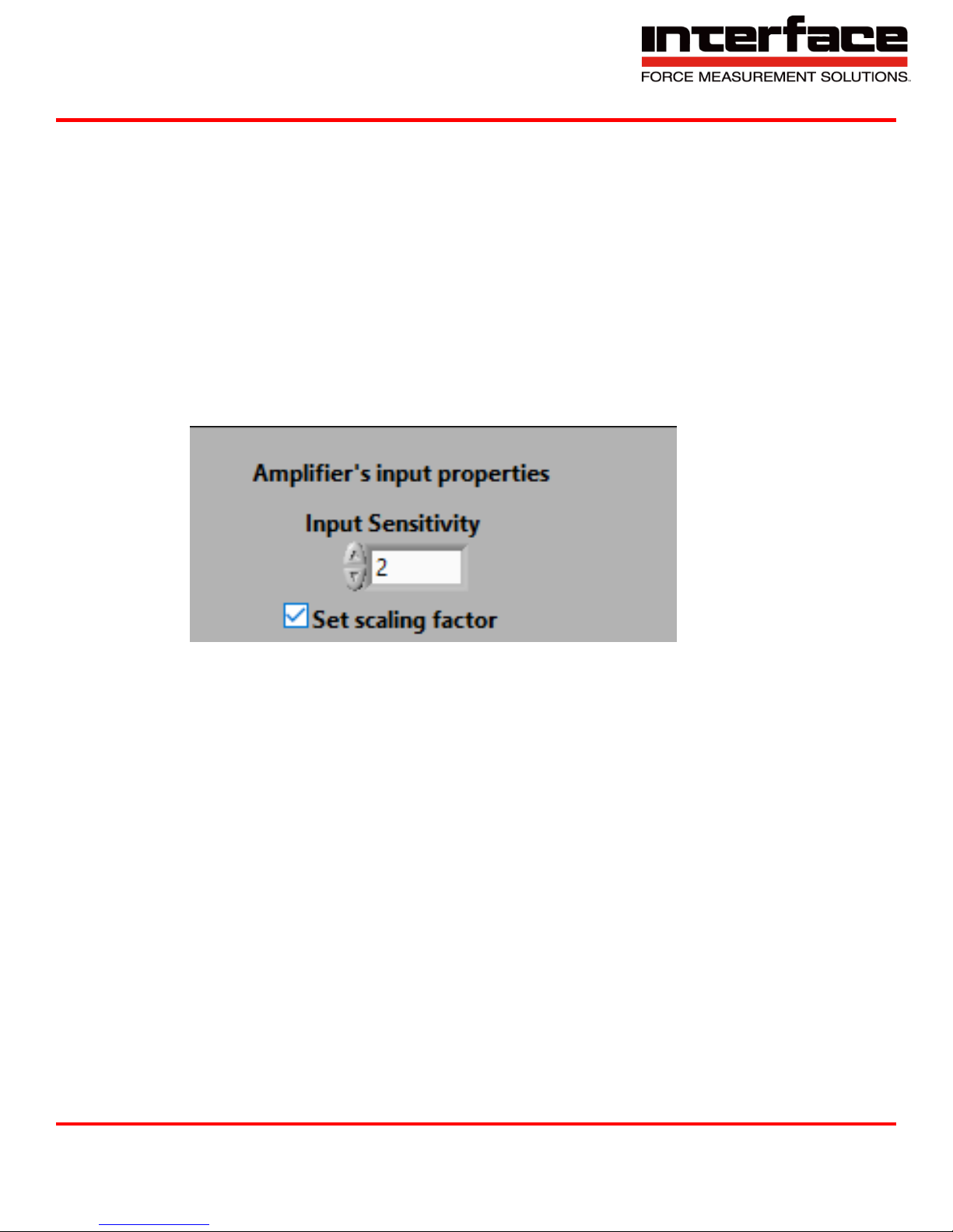
8.4. Amplifier’s input properties
8.4.1. Input Sensitivity – Change this value if it doesn’t match the input sensitivity of the measuring
amplifier where the strain ages are connected to. Normally the value shown is the correct
value, some GSV-2 or GSV-4 measuring amplifiers do communicate the correct value to the
program. Together with the gauge factor, this value will be used to calculate the correct
scaling factor automatically after the OK button is pressed. NOTE: The strain gauges must be
wired in a quarter bridge configuration in order to calculate the scaling factor correctly.
8.4.2. Set Scaling factor – Uncheck this checkbox if you are sure that the scaling factors of the
channels where the three strain gauges are connected to are already correct. If checked, the
new scaling factor will be calculated automatically according to the gauge factors and the
input sensitivity settings. NOTE: the strain gauges must be wired in a quarter bridge
configuration in order to calculate the new scaling.
FIGURE 85 - AMPLIFIER'S INPUT PROPERTIES
Interface Inc. ● 7401 East Butherus Drive, Scottsdale, Arizona 85260 USA ● Phone 480.948.5555 ● Fax 480.948.1924
Document Number 15-216 Rev B Page 66 of 74
Page 67
9330 Operating Manual
9. TEDS – Transducer Electronic Data Sheet
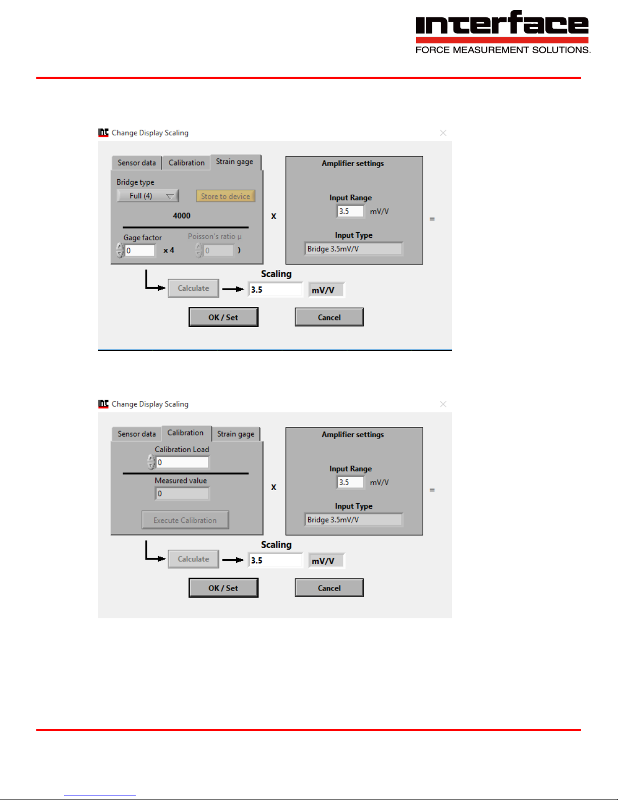
10. Strain gage
FIGURE 86 - STRAIN GAGE
11. Calibrate
FIGURE 87 - CALIBRATE
Interface Inc. ● 7401 East Butherus Drive, Scottsdale, Arizona 85260 USA ● Phone 480.948.5555 ● Fax 480.948.1924
Document Number 15-216 Rev B Page 67 of 74
Page 68
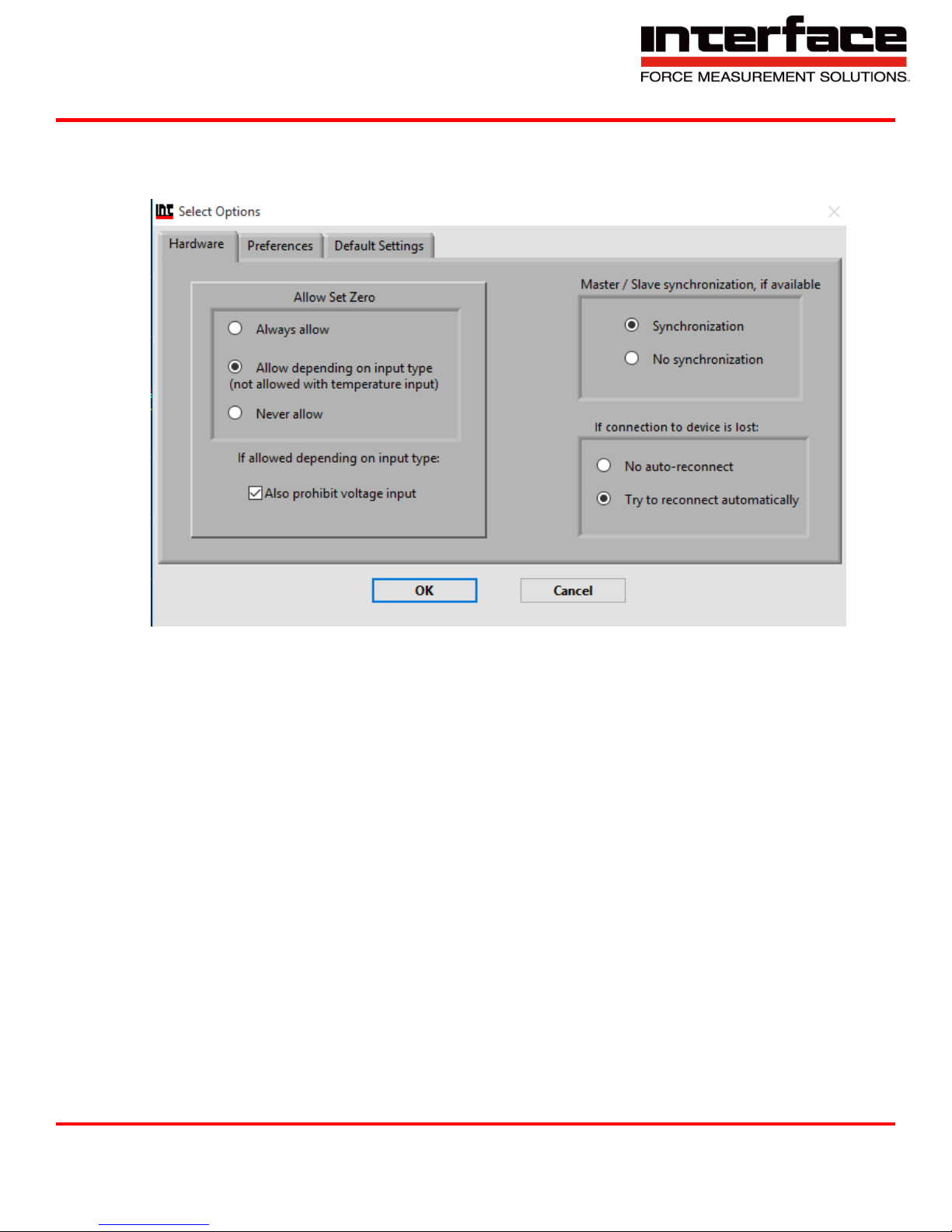
Options
1. Hardware
9330 Operating Manual
FIGURE 88 - HARDWARE
Interface Inc. ● 7401 East Butherus Drive, Scottsdale, Arizona 85260 USA ● Phone 480.948.5555 ● Fax 480.948.1924
Document Number 15-216 Rev B Page 68 of 74
Page 69
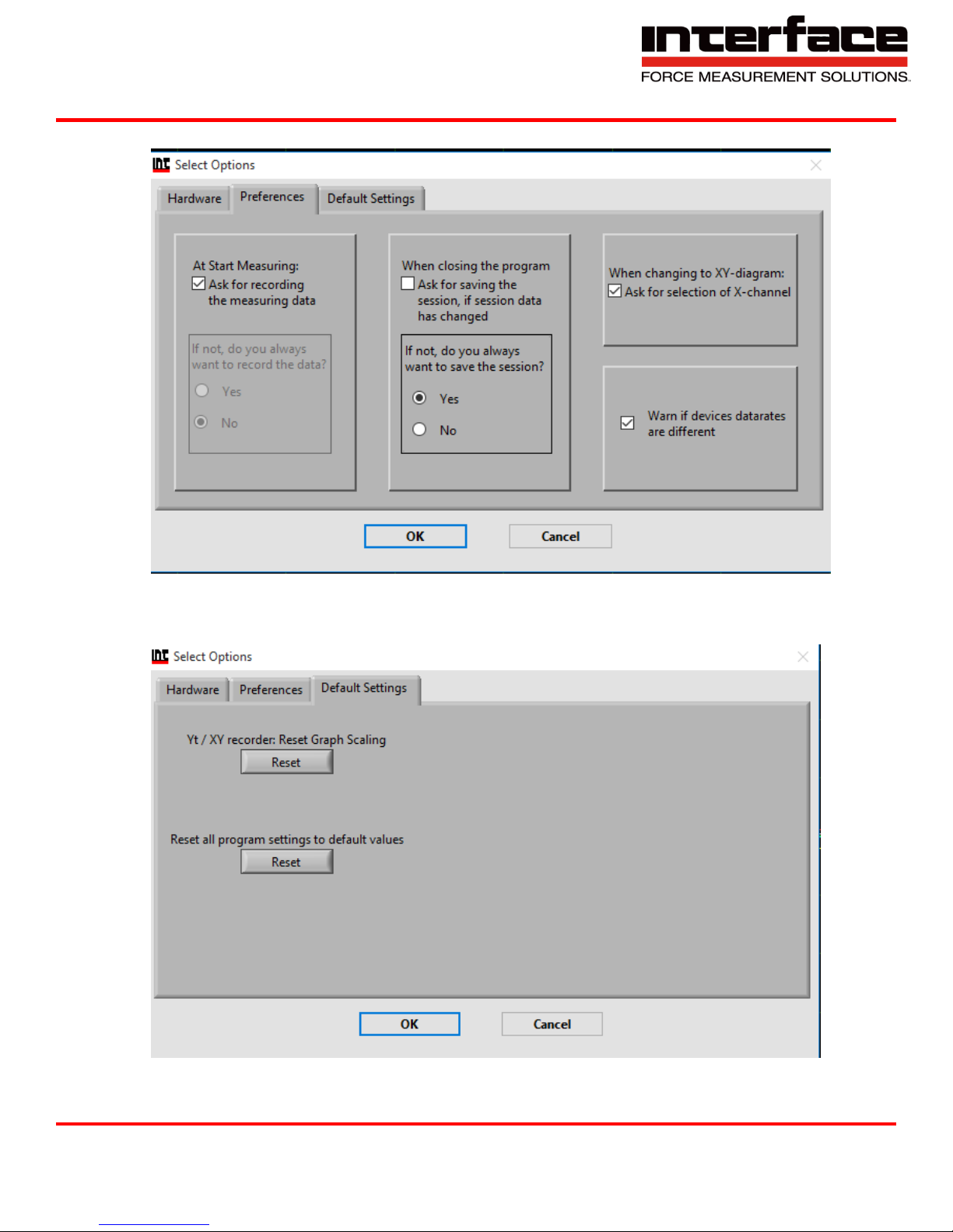
2. Preferences
9330 Operating Manual
FIGURE 89 - PREFERENCES
3. Default Settings
FIGURE 90 - DEFAULT SETTINGS
Interface Inc. ● 7401 East Butherus Drive, Scottsdale, Arizona 85260 USA ● Phone 480.948.5555 ● Fax 480.948.1924
Document Number 15-216 Rev B Page 69 of 74
Page 70
9330 Operating Manual
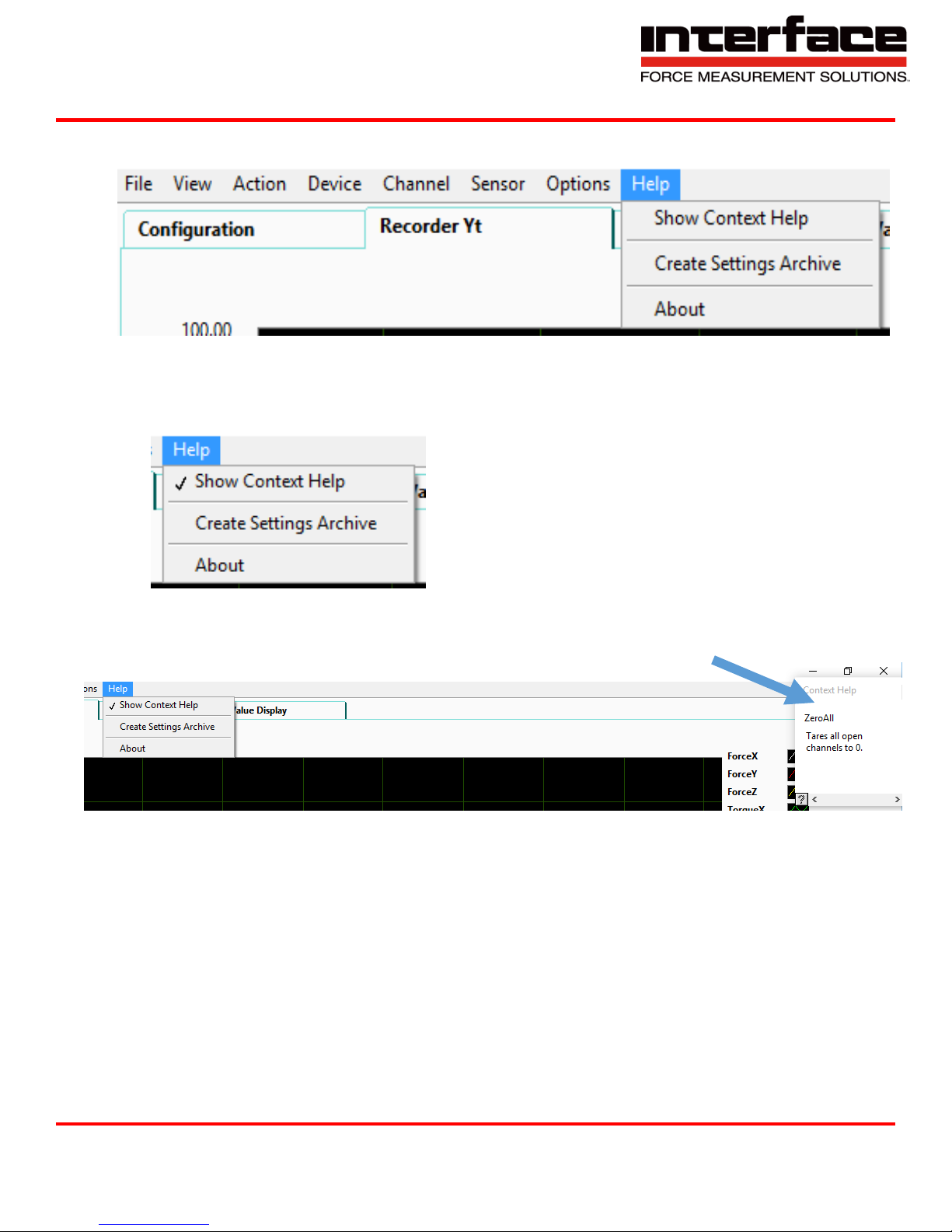
Help
FIGURE 91 - HELP
1. Show Context Help
FIGURE 92 - SHOW CONTEXT HELP
2. A box will appear on the corner with a definition of each function.
FIGURE 93 - CONTEXT HELP POPUP
Interface Inc. ● 7401 East Butherus Drive, Scottsdale, Arizona 85260 USA ● Phone 480.948.5555 ● Fax 480.948.1924
Document Number 15-216 Rev B Page 70 of 74
Page 71
9330 Operating Manual
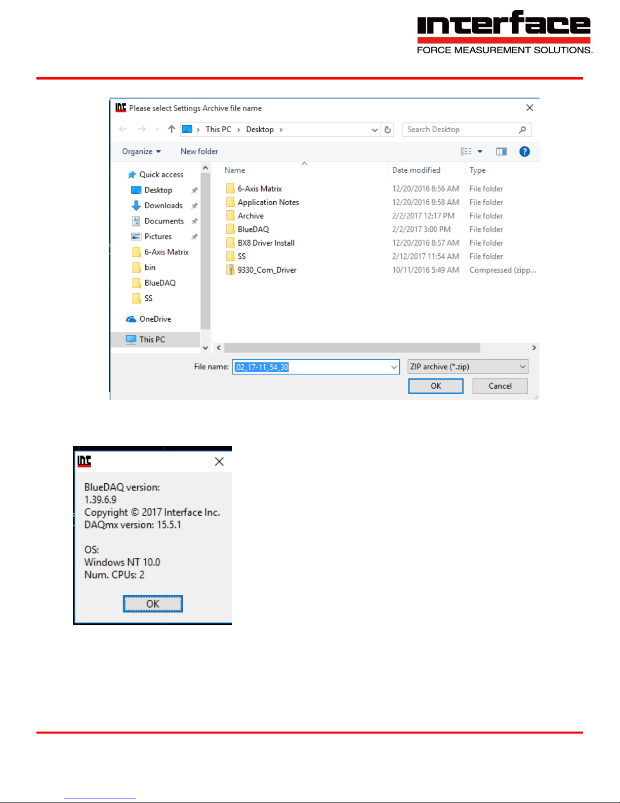
3. Create Settings Archive
FIGURE 94 - CREATE SETTINGS ARCHIVE
4. About lets you know the BlueDAQ version number.
FIGURE 95 – ABOUT
Interface Inc. ● 7401 East Butherus Drive, Scottsdale, Arizona 85260 USA ● Phone 480.948.5555 ● Fax 480.948.1924
Document Number 15-216 Rev B Page 71 of 74
Page 72
9330 Operating Manual
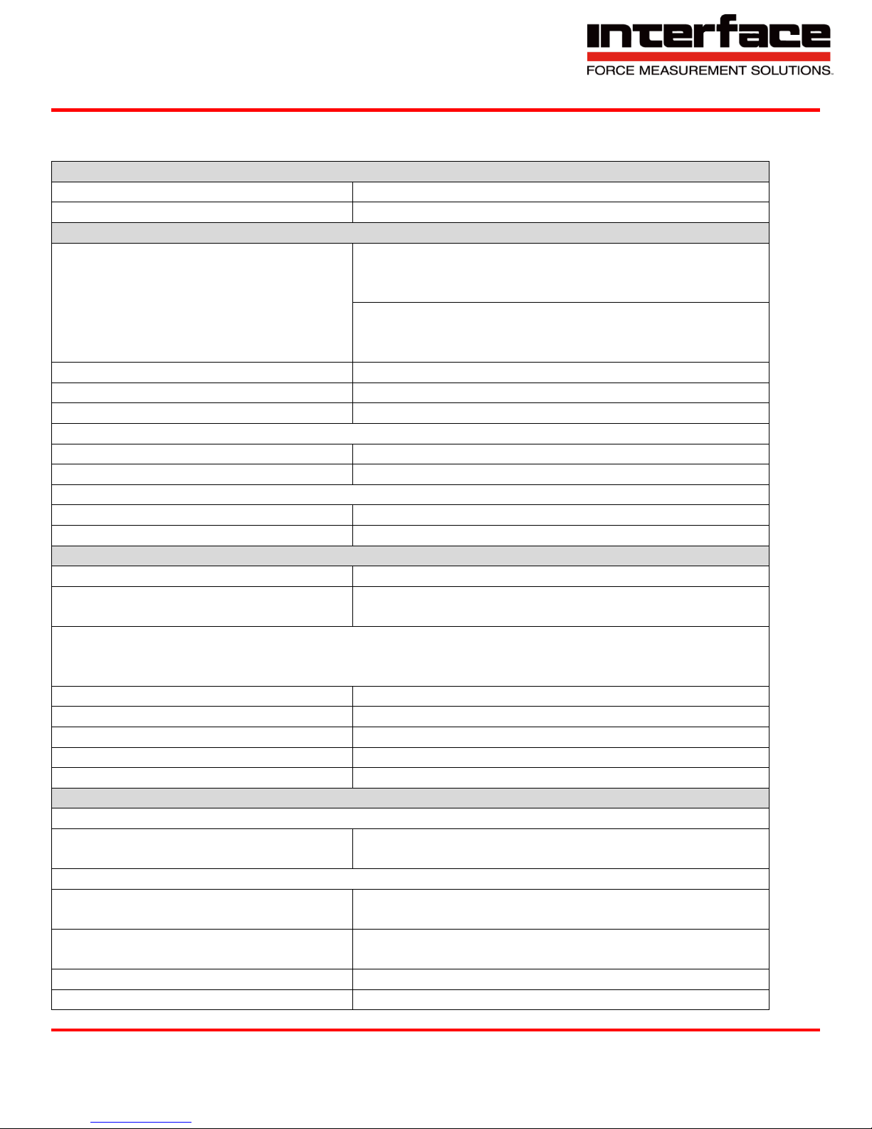
Accuracy Class
Analog
0.1%
Digital
0.05%
Inputs
Measurement Range
±1mV/V
(JP1 on 1 with 5V sensor supply)
±2mV/V or ±3.5 per software)
±3.5mv/V per software)
(JP1 on 2 with 2.5V sensor supply)
Connectible full bridge
4 x 350 Ohm
Bridge supply voltage
2.5V/5V
Input Impedance
>20MOhm (300pF)
Common mode rejection
DC
>120 dB
100Hz
>100 dB
Analog Input 1
Input voltage range
0 - 10V
Input resistance
56 kOhm
Accuracy
Linearity deviation
<0.02% of unit
Influence of temperature on the zero
point per 10K
Measurement range 1mV/V: <0.4 type 0.2% of unit
Measurement range 2mV/V: <0.2 type 0.1% of unit
Influence of temperature on the measurement sensitivity per 10K referring to the
measured value
Analog output
<0.1; type 0.05%
Display / digital
<0.1; type 0.005%
Resolution
Peak Value
>30000 parts
RMS
>150000 parts
Output
Analog Output Filter
-3dB cut-off frequency, Bessel,
2. order
3.5; 260; 1700 Hz (can be switched using software)
Digital Output Filter
3dB cut-off frequency
0.06-1700 Hz
Digital output measuring
rate
0-3750 Hz
Analog Output
±5V
Source resistance
47 Ohm
Technical Data
Interface Inc. ● 7401 East Butherus Drive, Scottsdale, Arizona 85260 USA ● Phone 480.948.5555 ● Fax 480.948.1924
Document Number 15-216 Rev B Page 72 of 74
Page 73
9330 Operating Manual
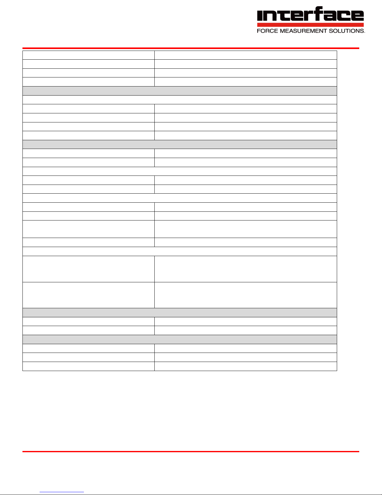
Control cables
High level: 3.4V (active high)
Automatic zero-point adjustment
Low Level: <1.4V
Control cables
High level: 3.4V (active high)
Automatic zero-point adjustment
Low Level: <1.4V
Supply
Supply voltage
Nominal range
7 - 27VDC
Operating range
6 - 30VDC
Power Input
2 (charge battery: max. 11VA)
Battery
31.2 Wh
Operating time with battery
Normal operation
Max. 20 Hours
Standby
Max 300 Days
Duration of battery charging
Supply voltage 10-27V
Max. 6 Hours
Supply with USB (standby operation)
Max. 27 Hours
Interface
USB Version
2.0 Fullspeed
Device classes
Mass Storage Device, Communication Device Class
Memory card
SD (1.x), SDHC, class6 or 10, (not UHS-1 and not
UHS-2)
File system
FAT16, FAT32
Functions, user menu (selection)
Parameter memory
Last setting (automatic)
Manufacturer’s settings
6 parameter sets
Other functions
- programmable amplification
- programmable adjustment of the digital final value
- activation of the zero-point adjustment
Temperature range
Nominal temeperature range
0 to 50 C
Storage temperature range
-20 to 70 C
Dimensions
L x H x T
164 x 105 x 32
Weight
610g
Protection class
IP51 / IP65
Absolute limit values
(all voltages based on supply chassis)
Differential input:: -12 to +12V
Sense inputs: -12 to +12V
Control cables: -30 to +30V
Interface Inc. ● 7401 East Butherus Drive, Scottsdale, Arizona 85260 USA ● Phone 480.948.5555 ● Fax 480.948.1924
Document Number 15-216 Rev B Page 73 of 74
Page 74
9330 Operating Manual
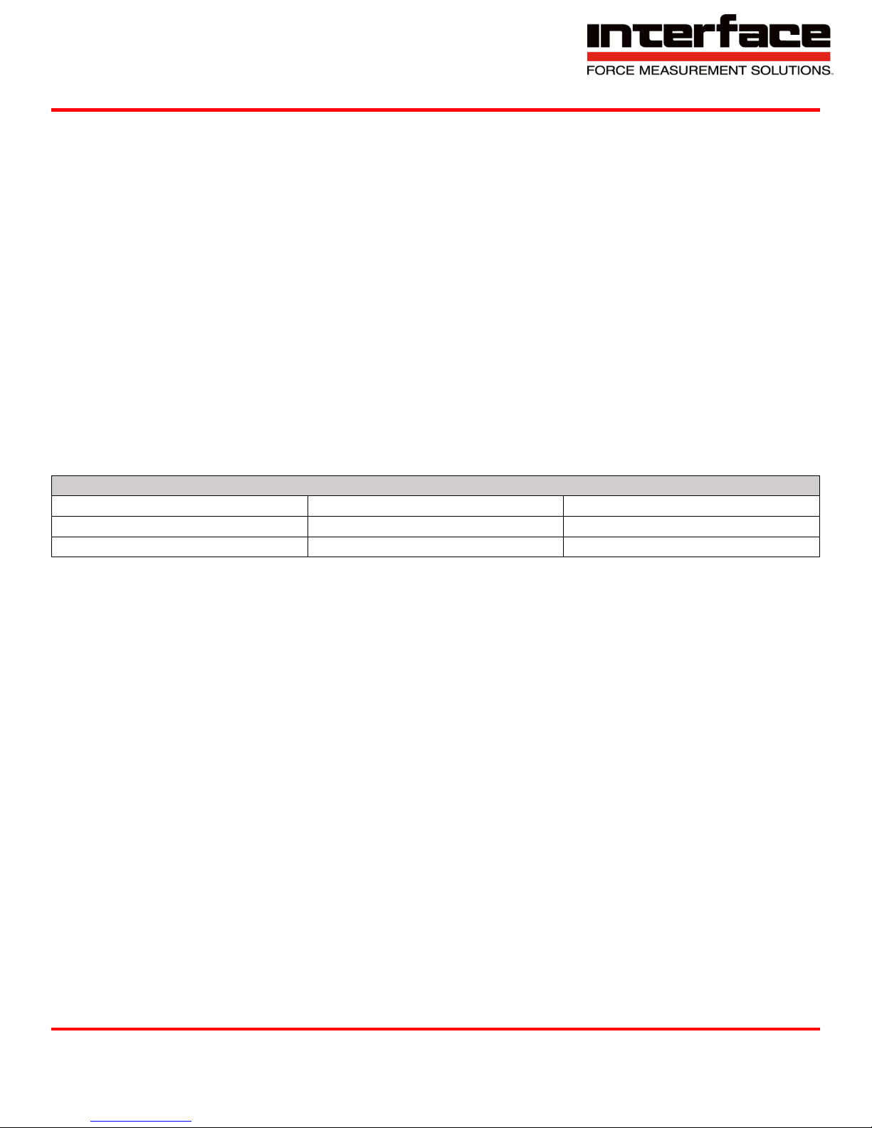
Revision History
Author
Revision
Release Date
KB A -
PB B 09/12/2018
Warranty
All Telemetry products from Interface Inc., ('Interface') are warranted against defective material and
workmanship for a period of (1) one year from the date of dispatch. If the 'Interface' product you
purchase appears to have a defect in material or workmanship or fails during normal use within the
period, please contact your Distributor, who will assist you in resolving the problem. If it is necessary
to return the product to 'Interface' please include a note stating name, company, address, phone
number and a detailed description of the problem. Also, please indicate if it is a warranty repair. The
sender is responsible for shipping charges, freight insurance and proper packaging to prevent
breakage in transit. 'Interface' warranty does not apply to defects resulting from action of the buyer
such as mishandling, improper interfacing, operation outside of design limits, improper repair or
unauthorized modification. No other warranties are expressed or implied. 'Interface' specifically
disclaims any implied warranties of merchantability or fitness for a specific purpose. The remedies
outlined above are the buyer’s only remedies. 'Interface' will not be liable for direct, indirect, special,
incidental or consequential damages whether based on the contract, tort or other legal theory. Any
corrective maintenance required after the warranty period should be performed by 'Interface'
approved personnel only.
Interface Inc. ● 7401 East Butherus Drive, Scottsdale, Arizona 85260 USA ● Phone 480.948.5555 ● Fax 480.948.1924
Document Number 15-216 Rev B Page 74 of 74
 Loading...