

Page 1
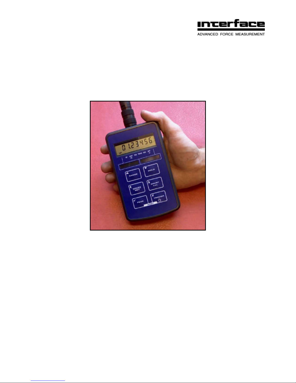
9320 Manual
Portable Battery Powered Indicator
Interface, Inc. • 7401 E. Butherus Dr. • Scottsdale, AZ 85260 • 800-947-5598 • 480-948-1924 (fax)
www.interfaceforce.com
Page 2

1
CONTENTS
INTRODUCTION........................................................................................................................................................................................2
USER OPERATION..............................................................................................................................................................................2
Electrical Connection Information..........................................................................................................................................................3
Sensor Connections.........................................................................................................................................................................3
RS232 Port Connections.................................................................................................................................................................. 3
Internal Connections........................................................................................................................................................................3
MENU STRUCTURE.............................................................................................................................................................................5
CONFIGURATION MENU.....................................................................................................................................................................7
CALIBRATION MENU...........................................................................................................................................................................9
Operation Features .............................................................................................................................................................................10
Normal Display Operation..............................................................................................................................................................10
Switching the 9320 On/Off.............................................................................................................................................................10
RANGE Button...............................................................................................................................................................................10
HOLD Button ..................................................................................................................................................................................11
GROSS/NET Button......................................................................................................................................................................11
SHUNT CAL Button .......................................................................................................................................................................11
PEAK Button..................................................................................................................................................................................11
TROUGH Button............................................................................................................................................................................11
CONFIGURATION MENU Parameters...............................................................................................................................................12
CALIBRATION MENU Parameters.....................................................................................................................................................14
Calibration Procedures..................................................................................................................................................................15
Specifications......................................................................................................................................................................................17
Mechanical Dimensions......................................................................................................................................................................17
Warranty..............................................................................................................................................................................................18
Interface 9320 User Manual Issue 1.0
Page 3
2
INTRODUCTION
The 9320 portable load cell readout is a microprocessor based portable instrument
designed to be compatible with any full bridge sensor with an output sensitivity of up to
50mV/V. Bridge resistances from 85Ω upwards can be used with the 9320.
Configuration and calibration of the 9320 is achieved using the front panel push buttons to
navigate through a very simple menu structure.
User functions available on the 9320 include:
• Range Selection
• Display Hold/Freeze
• Gross/Net indication selection
• Peak Hold selection
• Trough Hold selection
• Shunt Cal check
The 9320 is powered by two internal non-rechargeable AA alkaline batteries.
There is an option to have rechargeable alkaline batteries, which can be charged without
the need for removing them from the 9320.
USER OPERATION
Important Note
The unit is typically supplied calibrated to a particular load cell. All user functions are
available via the front keypad. Do not attempt to re-calibrate the 9320, unless you are
authorised and have the equipment available to do so.
Interface 9320 User Manual Issue 1.0
Page 4
3
Electrical Connection Information
Sensor Connections
The standard sensor connection is a 5 pin 723 series Binder connector. The sensor
connector is also used as a charging socket, when the re-chargeable alkaline battery
option has been ordered, the wiring for this is detailed below:
PIN 1 +ve Excitation
PIN 2 -ve Excitation & -ve Charge Input
PIN 3 +ve Signal
PIN 4 -ve Signal
PIN 5 +ve Charge Input
RS232 Port Connections
If the 9320 has been ordered with the optional RS232 output, then this will be available via
a 7 pin 723 series Binder connector. The wiring for this is as detailed below:
PIN 1 Tx
PIN 2 Rx
PIN 3 Gnd
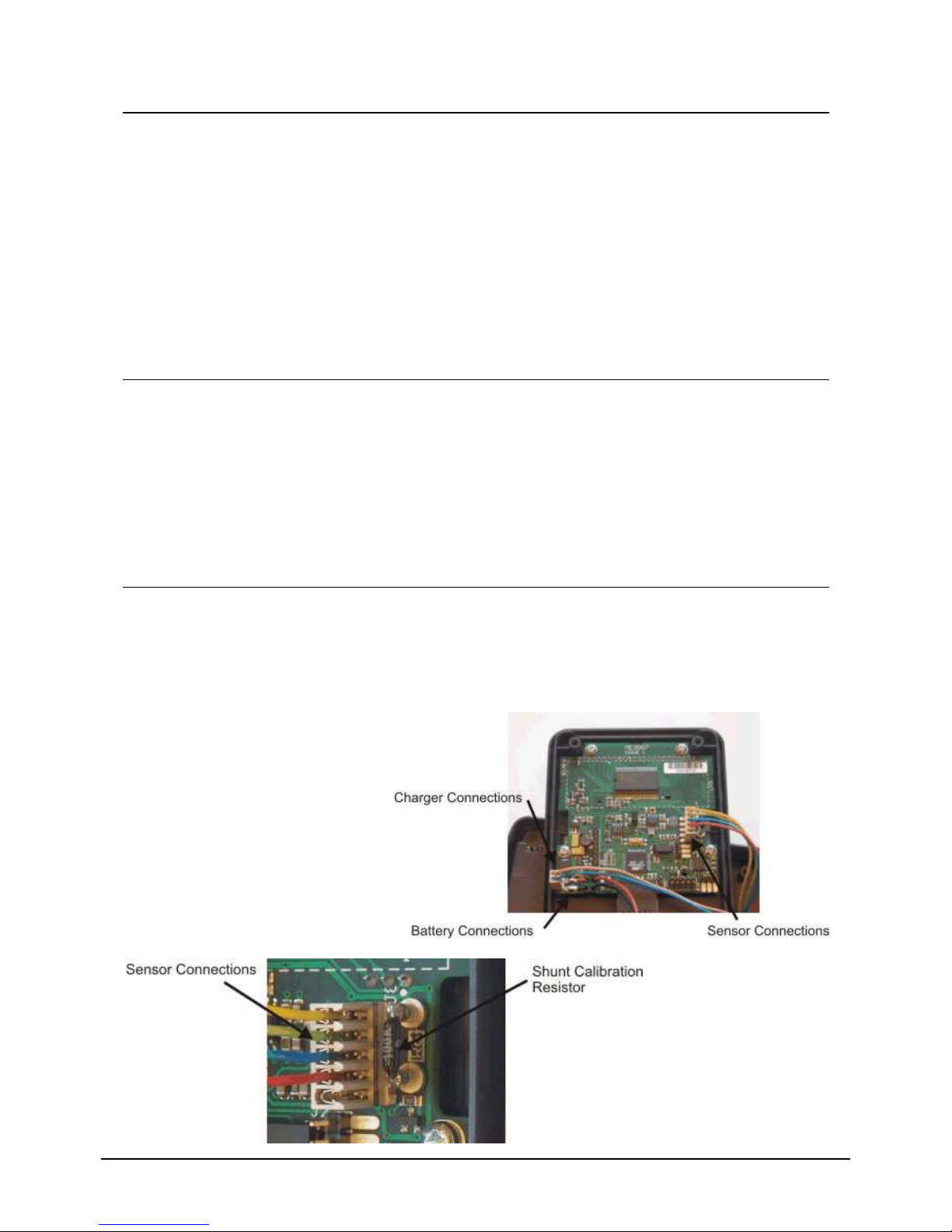
Internal Connections
It may be necessary from time to time to know what the internal connections are. For
example, if you disturb some of the connections while trying to insert the range legends, or
if you need to change the internal shunt calibration resistor. These are shown below for
reference only:
Interface 9320 User Manual Issue 1.0
Page 5
4
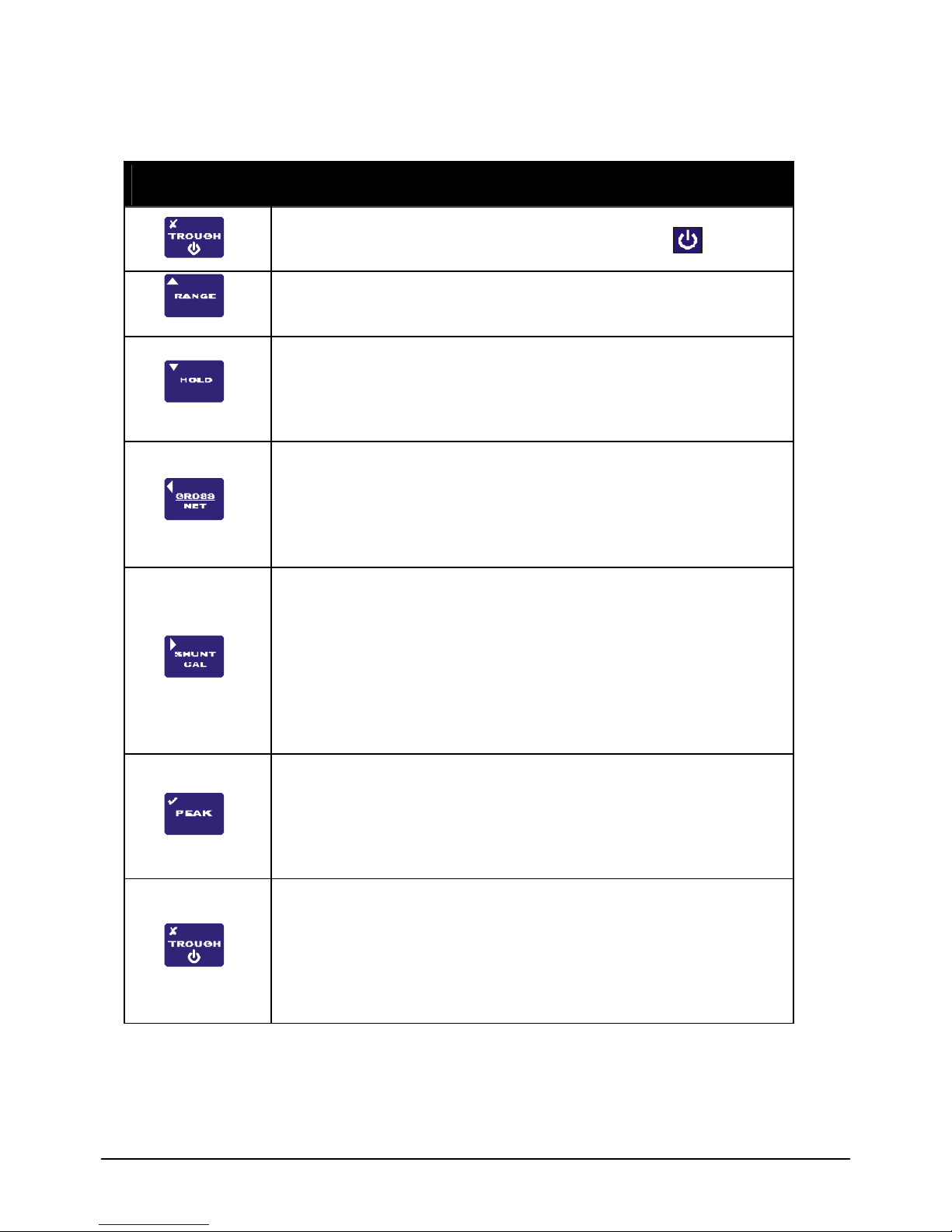
There are six push buttons on the front panel of the 9320, which are available for use in
normal operation. Each of these is described below:
Front Panel
Button
Function of Button in Normal Operation Mode
To switch the 9320 ON or OFF press and hold the button.
The RANGE button allows the user to toggle between two
independent scales. The range that has been selected is
highlighted by an annunciator.
The HOLD button allows you to hold/freeze the current display
value when the button is pressed. Pressing the HOLD button
again releases the display. The HOLD annunciator is illuminated
when in the HOLD mode, and the display will flash, to alarm
further that the user is not viewing instantaneous display values.
The GROSS/NET button, when pressed, allows the user to
toggle between displaying the Gross or Net display values. This
can be useful in many applications where it is necessary to
display the change in display value from a certain part of the
measurement range. When in NET mode the NET annunciator is
lit. When in GROSS mode, the NET annunciator is not lit.
The SHUNT CAL button allows the user to press this at any
point in time. The standard unit shunts a 100k? resistor across
the negative excitation and negative signal connections. If this is
performed at the end of the calibration procedure, then a figure
can be noted, so the user can check calibration accuracy or
connection integrity. The button has to be he ld down to operate.
When held down the SHUNT CAL annunciator is lit and the
display will flash, to alarm further that the user is not viewing
instantaneous display values.
When the PEAK button is pressed the display will show the last
Peak reading. To r eset the Peak readings press the PEAK and
TROUGH buttons simultaneously. When in PEAK mode the
PEAK annunciator will be lit and the display will flash, to alarm
further that the user is not viewing instantaneous display values.
To turn off Peak mode press the PEAK button.
When the TROUGH (valley) button is pressed the display will
show the last Trough reading. To reset the Trough readings
press the TROUGH and PEAK buttons simultaneously. When in
TROUGH mode the TROUGH annunciator will be lit and the
display will flash, to alarm further that the user is not viewing
instantaneous display values. To turn off the Trough mode press
the TROUGH button
Interface 9320 User Manual Issue 1.0
Page 6
5
MENU STRUCTURE
1?
0.5?
00
EnAbLEd?
NORMAL DISPLAY
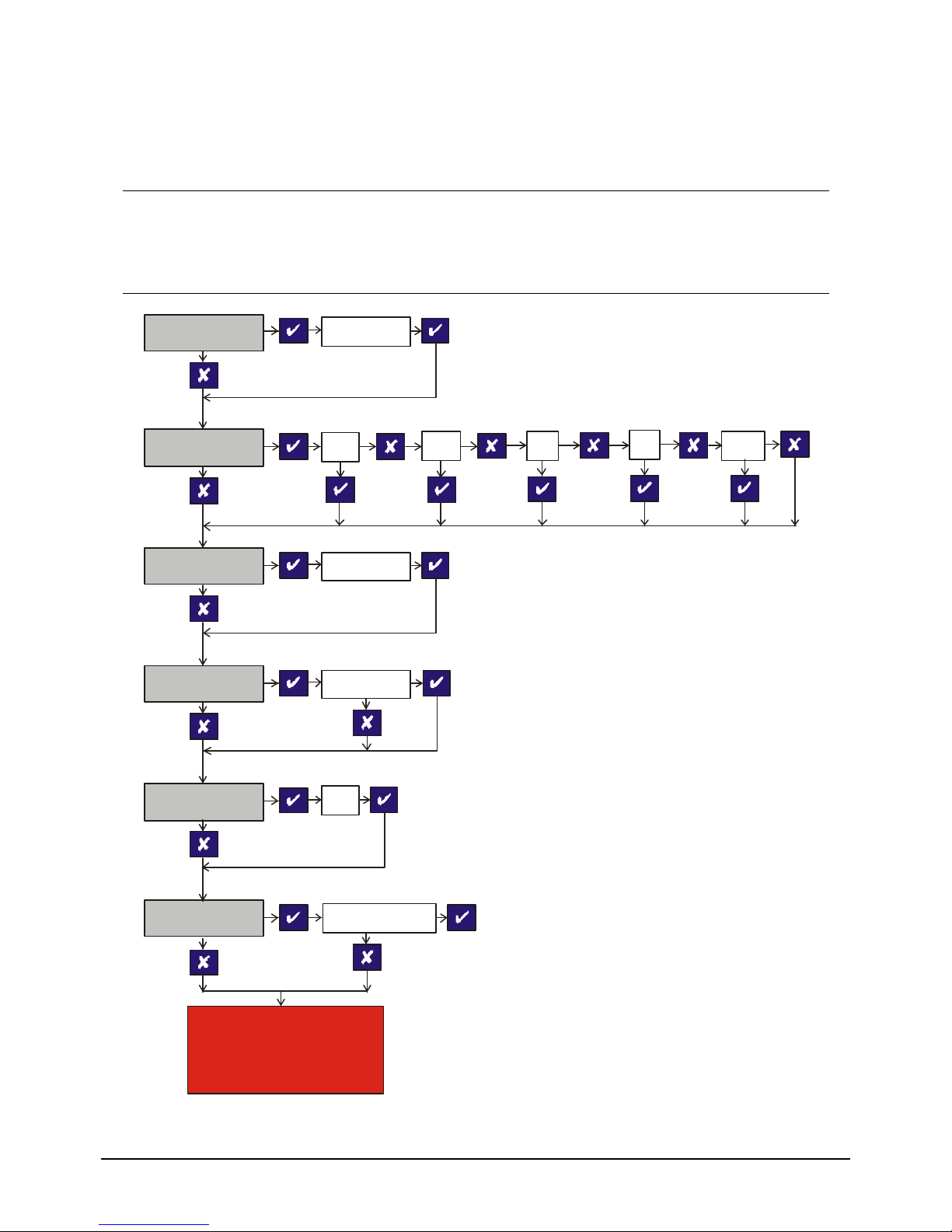
The 9320 has two menus, details of which are outlined below:-
A CONFIGURATION MENU, which enables the user to tailor the operation to meet a
specific application requirement. The values selected in the CONFIGURATION MENU are
completely independent for each range.
SEt ZErO
SEt rAtE
SEt OUEr
SEt OPEr
0000000
25?
0000000
PSAVE?
10?
3?
AutO OFF
rS232
RETURN TO
MODE
Interface 9320 User Manual Issue 1.0
Page 7
Interface 9320 User Manual Issue 1.0
6
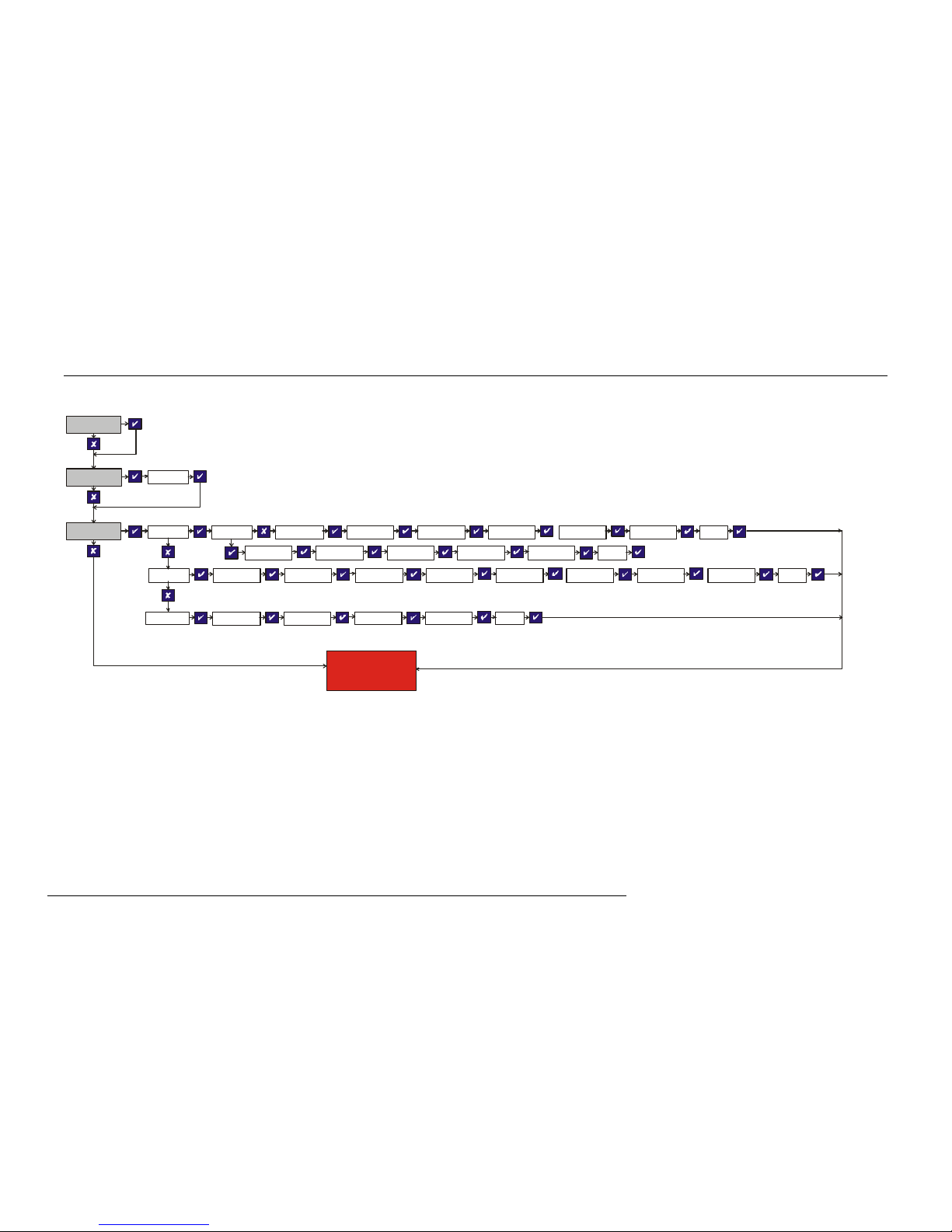
A CALIBRATION MENU, which is used to calibrate each of the two ranges with independent scales, as well as setting the display
resolution for each range.
SEnS 5.0
SEt rES
CALibrAt LiVE?
RETURN TO
NORMAL DISPLAY
MODE
0000.000
uSE SC?
APPLY LO dISP LO 0000000
APPLY HI
dISP HI
0000000
donE
APPLY LO dISP LO 0000000
dISP HI
0000000
donE
tAbLE? InPut LO 0000000
dISP LO 0000000 InPut HI
0000000
dISP HI
0000000
donE
CAL VAL? SEt 9Ain 0000000
SEt OFFS donE0000000
Page 8
7
CONFIGURATION MENU
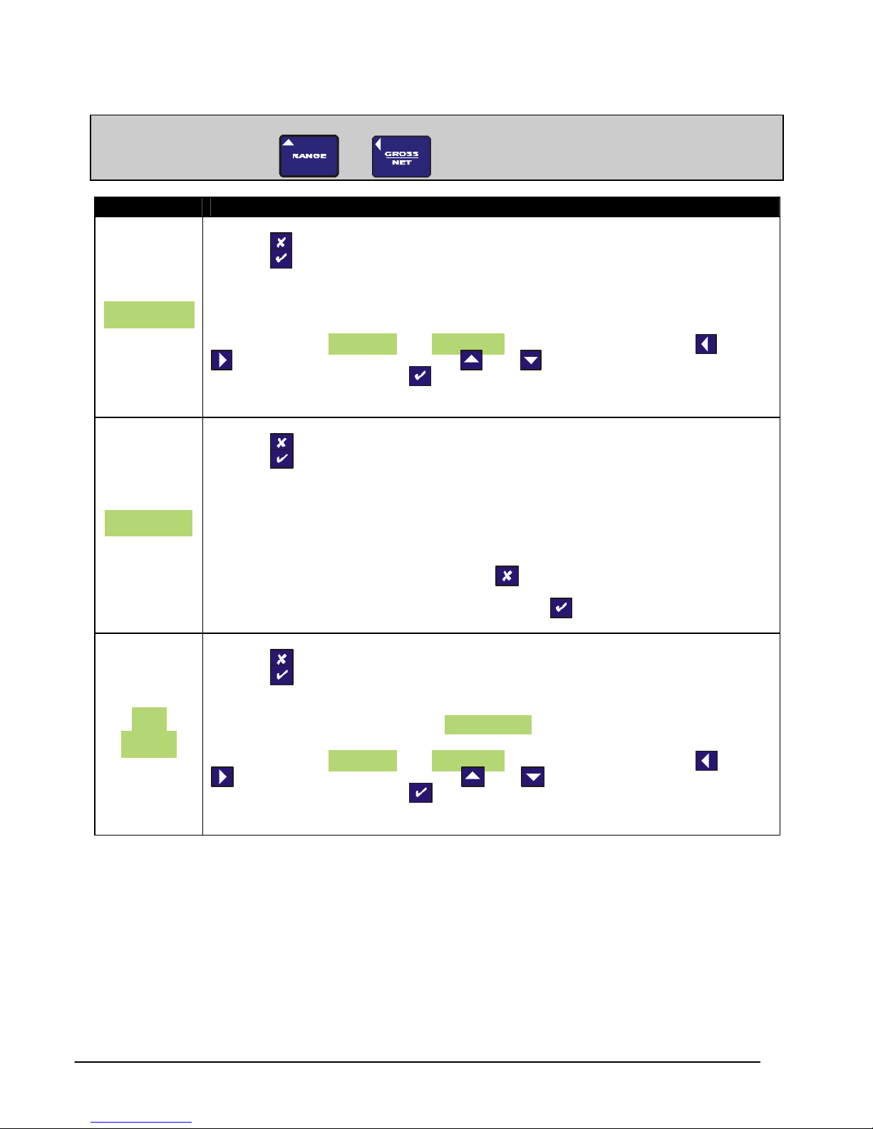
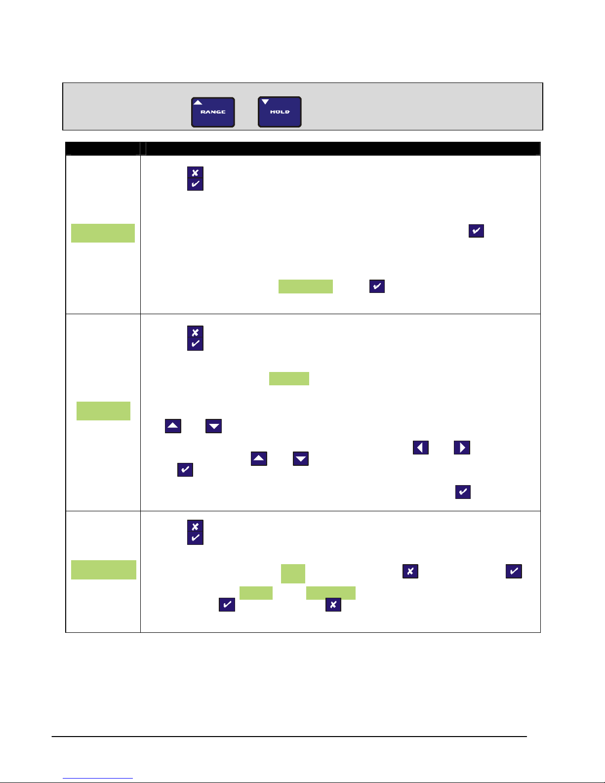
To enter the CONFIGURATION MENU, press and hold
Parameter Set-up Information
PRESS TO SKIP TO NEXT MENU ITEM
PRESS TO SET A NEW SYSTEM ZERO
This allows the user to introduce a fixed offset to the display value. The
SEt ZEro
SEt rAtE
SEt
OUEr
GROSS and NET values are then displayed with this offset taken into account.
Values between -9999999 and +9999999 can be entered, using the and
arrows to select a digit and the and arrows to increment or
decrement the digits. Press to accept the value and move onto the next
parameter.
PRESS TO SKIP TO NEXT MENU ITEM
PRESS TO CHANGE THE UPDATE RATE
This allows the user to se t the display update rate, the options available is the
update rate of the display in Hz. Please note that the 25Hz update is only
available in PEAK or TROUGH mode.
When you choose to change the update rate you will be prompted whether you
want to select 25Hz, if you do not press you will then be prompted to
select any of the other values, which in order, are 10Hz, 3Hz, 1Hz, 0.5Hz. to
set the update rate for the value you want press
PRESS TO SKIP TO NEXT MENU ITEM
PRESS TO SET OVERLOAD ALARM
This allows the setting of a visual overload. The value entered is the display
value at which the 9320 displays OUErLOAd.
Values between -9999999 and +9999999 can be entered, using the and
arrows to select a digit and the and arrows to increment or
decrement the digits. Press to accept the value and move onto the next
parameter.
and
buttons for 3 seconds.
Interface 9320 User Manual Issue 1.0
Page 9
8
Parameter Set-up Information
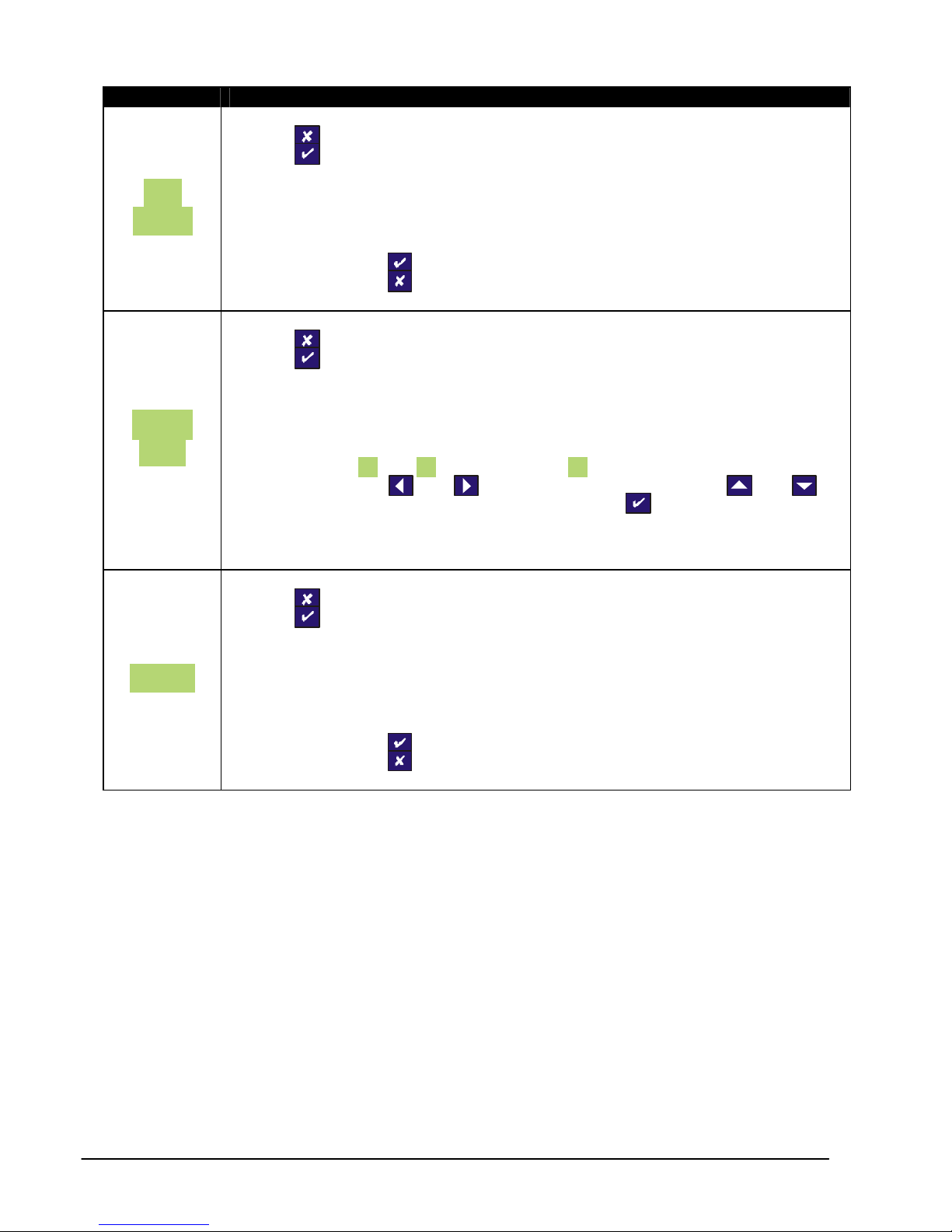
PRESS TO SKIP TO NEXT MENU ITEM
PRESS TO SELECT OPERATION MODE
SEt
This allows the enabling or disabling of the powe r save mode, which updates at
1 update per second and pulses the sensor excitation. This results in a lower
OPEr
accuracy (1 part in 20,000).
To enable press
To disable press
PRESS TO SKIP TO NEXT MENU ITEM
PRESS TO SET AUTO POWER OFF
This enables the setting of an auto power off value. The value entered is in
minutes. If no front panel buttons are pressed for the time set here, then the
AUtO
OFF
indicator will automatically power off, to conserve battery life.
Values between 05 and 99 can be entered (00 leaves the 9320 permanently
powered), using the and arrows to select a digit and the and
arrows to increment or decrement the digits. Press to accept the value and
move onto the next parameter.
PRESS TO SKIP THIS PARAMETER AND EXIT MENU
PRESS TO ENABLE THE RS232 OUTPUT
This feature enables you to enable or disable the RS232 output. Further details
rS232
of the RS232 format are provided further into this manual. The RS232 output is
an option that has to be ordered with the 9320. To conserve battery life, it is
suggested that the RS232 output is disabled, when it is not required.
To enable press
To disable press
.
.
Interface 9320 User Manual Issue 1.0
Page 10
9
CALIBRATION MENU
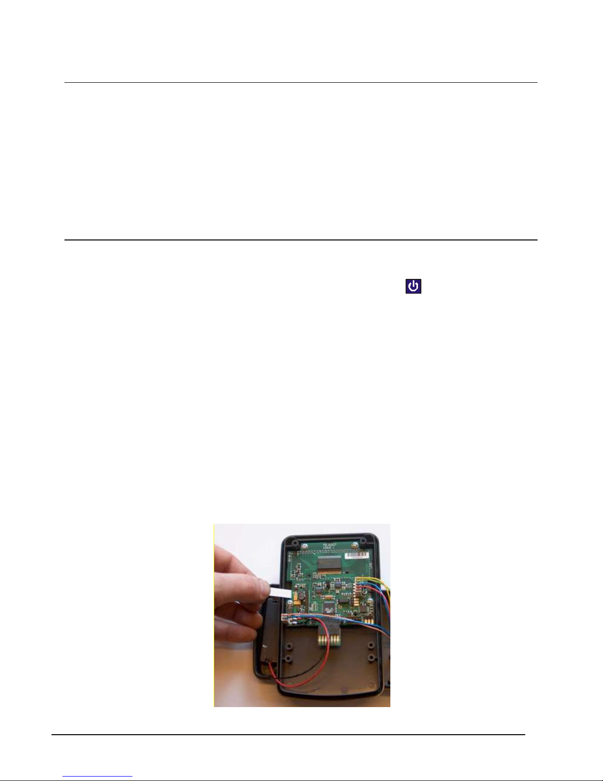
To enter the CALIBRATION MENU, press and hold
Parameter Set-up Information
PRESS TO SKIP TO NEXT MENU ITEM
PRESS TO CHANGE SENSOR INPUT SENSITIVITY
This allows the calibration engineer to change the sensitivity range of the 9320,
when connecting to sensors with a sensitivity of greater than 5mV/V. The 9320
SEnS 5.0
is factory set for 5mV/V. To ensure the unit is set to 5mV/V press
To select 50mV/V you need to power down the unit and access the internal
circuit board. Move link LK1 and place it onto JP1. Power on the 9320 and
return to this point of the calibration menu. You will notice that the menu
parameter has changed to SEnS 50.0, press to change the sensitivity to
50mV/V and move on to the next parameter.
PRESS TO SKIP TO NEXT MENU ITEM
PRESS TO THE SET THE DISPLAY RESOLUTION
This parameter sets the decimal point position for the display and the
resolution, i.e. a value of 000.005 would display the reading to 3 decimal
places and the readings will change in steps of 0.005.
SEt rES
The decimal point position is moved one place to the right each time you press
the and together.
Any value can be entered for the resolution, using the and arrows to
select a digit and the and arrows to increment or decrement the digits.
Press to accept the value and move onto the next parameter.
To save the settings and move on to the next parameter press
PRESS TO SKIP THIS PARAMETER AND EXIT MENU
PRESS TO THE ENTER THE CALIBRATION ROUTINE
If you have chosen to enter the calibration routine you will be prompted
CALibrAt
whether you want to select LiVE, if you do not press, otherwise press .
You will then be prompted to select either of the other calibration methods,
which in order, are tAbLE and CAL VAL to select any of the calibration
methods press . Otherwise press
For more detailed calibration information, please refer to the calibration section
of the manual.
and
buttons for 5 seconds.
Interface 9320 User Manual Issue 1.0
Page 11
10
Operation Features
Normal Display Operation
The 9320 has a full 7 digit display, which can be scaled using the calibration menu to suit the
application it is to be used in. The display can display the instantaneous, peak or trough values.
It is also possible to hold the display value (this only operates when not in peak or trough
mode).
The display update rate, decimal point position and resolution can be set to suit.
The 9320 has two independent ranges. All values set in one range are totally independent from
the other.
Switching the 9320 On/Off
The 9320 is switched ON or OFF by pressing and holding down the button for 3 seconds.
It is also possible to set an Auto-off value in the configuration menu, so that the 9320
automatically switches itself off after a preset time, if there is no keyboard activity.
RANGE Button
The range feature allows for the setting of two totally independent setup ranges to be selected,
if required. To switch between ranges simply press the range button.
When you enter either the calibration menu or configuration menu, the parameters you will be
setting are those for the range you have selected. An annunciator is lit to identify which range
has been selected.
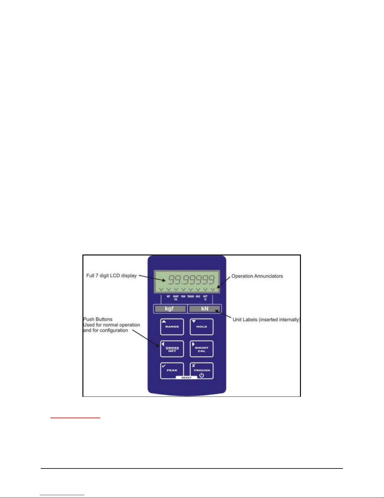
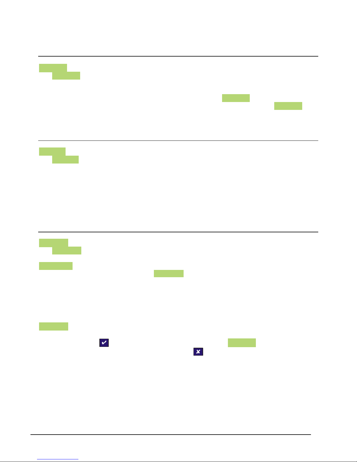
The 9320 is supplied with engineering unit legends; these can be slid into a window, located on
the inside of the front panel. These labels then help to further identify the units being displayed
for each range. Please refer to the photo below:
Interface 9320 User Manual Issue 1.0
Page 12

11
HOLD Button
The hold button allows the user to freeze the display when it is pressed. When pressed again
the display returns to it’s normal operating mode. When in hold mode the display will flash and
the hold annunciator will be lit, to ensure that this feature is not accidentally turned on without
the user noticing.
The hold feature can not be used when the 9320 is in either peak or trough hold mode.
GROSS/NET Button
The gross/net button, when pressed, toggles between the gross and net display values. This
enables the user to zero the display (by putting the 9320 into net mode) and displaying the
change in display value from that point.
This is useful for certain weighing applications where a tare weight exists, which can be
removed by putt ing the 9320 into net mode.
SHUNT CAL Button
The shunt calibration button, when pressed, puts an internal 100k ? resistor across the –ve
excitation and –ve signal of the sensor, generating a simulated output from the sensor,
therefore giving a simulated display value. This can be pressed immediately after the sensor
has been calibrated with the 9320 and noted down for later reference. The value noted can be
used to get an idea of the calibration accuracy at a later date, or for checking the integrity of the
sensor and sensor cabling.
The shunt calibration resistor can be changed to suit specific requirements. It is suggested that
a 15ppm ±0.1% tolerance resistor is used.
PEAK Button
When pressed this button puts the 9320 into peak mode. This will display the highest display
reading and hold it on the display until it is reset or a higher value is reached. To reset the peak
display, press the peak and trough buttons simultaneously. In peak mode it is possible to
capture peaks at a rate of up to 25Hz. To turn off the peak mode, press the peak button.
TROUGH Button
When pressed this button puts the 9320 into trough mode. This will display the lowest display
reading and hold it on the display until it is reset or a lower value is reached. To reset the trough
display, press the peak and trough buttons simultaneously. In trough mode it is possible to
capture troughs at a rate of up to 25Hz. To turn off the trough mode, press the peak button.
Interface 9320 User Manual Issue 1.0
Page 13
12
CONFIGURATION MENU Parameters
SEt ZEro Parameter
The SEt ZEro parameter is meant to be accessible to the user. It allows the removal of fixed
display offset values from the display, so that the GROSS and NET features can operate from a
zero point. This may also be considered as a manual tare facility. To zero the display, simply
enter the value that you wish to subtract from the display in the SEt Zero parameter. i.e. if the
display reads 000.103 and you wish it to read 000.000, then enter 000.103 in the SEt ZEro
parameter.
Different values can be set for each RANGE.
SEt rAtE Parameter
The SEt rAtE value sets the display update rate. The options available are 25Hz, 10Hz, 3Hz,
1Hz and 0.5Hz. Different updates rates can be set for each RANGE.
The 25Hz rate only updates at this rate when in the PEAK or TROUGH mode. When in normal
display mode it has been limited to a 3Hz update, as the digit fluctuations are impossible to view
with the human eye.
The 10Hz, 3Hz, 1Hz and 0.5Hz rates update the display every 100mS, 300mS, 1000mS and
2000mS respectively. The 9320 when it leaves the factory is set at 3Hz.
SEt OVEr Parameter
The SEt OVEr parameter allows the user to set a visual alarm. The value that is entered is the
display value that you want the alarm to activate at. When the alarm is activated the word
OVErLOad appears on the screen. To remove the alarm, the display value must be reduced to
a value that is lower than that set in the SEt OVEr parameter. This can be very useful as a
safety feature, or simply as a quick indication of when a preset level has been reached.
This value entered can be anywhere over the entire display range, so there are no limitations.
Different values an d settings are available for each RANGE.
SEt OPEr Parameter
The 9320 has a special power saving mode, which can be enabled or disabled within this
parameter, pressing when asked whether you wish to select P SAvE? will put the 9320 into
power save mode for the RANGE selected. Pressing will de-activate the power save facility.
When the power save facility is activated, battery life is conserved by pulsing on the excitation
voltage to the sensor. As a result the accuracy is reduced, as is the update rate. When in this
mode, the quickest update rate is 3Hz and the accuracy of the display is reduced to 1 digit in
10,000. It is important to note these limitations when deciding whether to use the power save
facility. However, it is also possible to set one RANGE with power save activated and the other
without.
Interface 9320 User Manual Issue 1.0
Page 14
13
The benefit is that the battery life, based on a 350 ? sensor bridge being connected, increases
from 45 hours to 450 hours.
It is also important to remember that when the 9320 is re-calibrated with a sensor, the power
save facility will be automatically turned off. The power save facility will therefore need to be reactivated after calibration has been completed.
AUtO OFF Parameter
The AUtO OFF parameter is another power saving feature. It allows for the setting of a time
period in minutes, between 05 and 99 (00 de -activates AUtO OFF). i.e. if this was set to 25,
then if the 9320 detects no keyboard activity for a continuous 25 minute period, then the 9320
will power down, to conserve power. If keybo ard activity is detected at any time during the 25
minute period, then the time period is restarted.
This can be a useful feature in a site environment, should the 9320 be left unintentionally
powered on.
rS232 Parameter
This parameter allows the user to enable the RS232 output form the 9320, by pressing
when prompted by EnAbLEd? On the display, pressing will disable the RS232.
The output format is ASCII. The display value is passed to the RS232 port each time the display
updates, with a carriage return at the end of each data string. The string information is as
follows:-
Baud Rate = 9600 baud
Stop bits = 1
Parity = None
Data bits = 8
Interface 9320 User Manual Issue 1.0
Page 15
14
CALIBRATION MENU Parameters
SEnS 5.0 Parameter
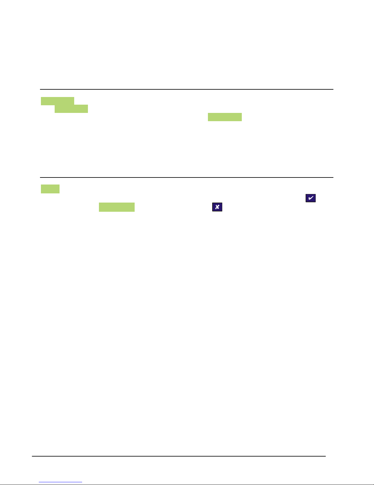
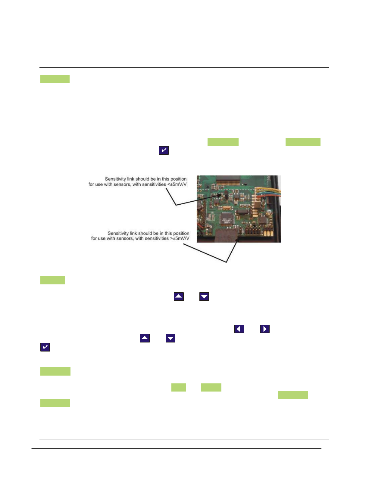
The 9320 is factory set to enable calibration with sensors generating an input signal of 5mV/V or
less. In the majority of cases it will not be necessary to read higher signal levels. If however, a
higher sensitivity sensor is used with the 9320, it will be necessary to gain access to the internal
PCB (you must turn the 9320 off) to move link LK1 to JP1 (see picture below) to allow the 9320
to accept sensitivities of up to 50mV/V.
Once this link has been moved, you will need to go back into the CALIBRATION MENU. When
re entering the menu, you will notice tha t the parameter SEnS 5.0 has changed to SEnS 50.0 to
change the sensitivity to 50mV/V press , the 9320 will now check the position of the link and
change the sensitivity. It will now be necessary to re-calibrate any sensors that you may
previously have calibrated to this instrument.
SEt rES Parameter
This parameter enables the setting of two features on the 9320. It allows you to set the decimal
point position of the display, by pressing the and together, to move the point position
(each press moves the decimal point position, one place to the right).
It also allows for the setting of the display resolution or the number of display counts the display
changes with an input change. To change the resolution use the and arrows to select a
digit you want to change and the and arrows to increment or decrement the digits. Press
to accept the value.
CALibrAt Parameter
This parameter is used to calibrate and scale the 9320 with a sensor. There are two basic
methods of calibration available. These are LiVE and tAbLE. There is also a third parameter,
which can be used for maintenance and recording purposes. This parameter is CAL VAL. The
CAL VAL value can be viewed after a calibration has been completed and will show the offset
and gain figures from any stored calibration. If these figures are noted, they can be used to reenter at a later date, if calibration data is lost for any reason, or if the calibration data from a
sensor needs to be transferred to another 9320.
Interface 9320 User Manual Issue 1.0
Page 16
15
Calibration Procedures
The best method of calibration, if it is possible to do so, is the LiVE calibration, as this reads in
the sensor signal at two calibration points and scales the 9320 automatically. If this is not
possible, then the sensitivity figure (in mV/V) from the sensor calibration certificate can be used
to scale the 9320, by using the tAbLE calibration. This may be the only option available if you
are unable to apply a known stimulus to the sensor, which quite often is the case.
LiVE Calibration Procedure
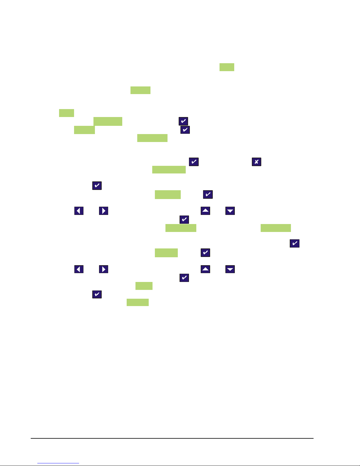
(1) When CALibrAt is displayed press
(2) LiVE ? will now be displayed, press
(3) You will be prompted uSE SC ?, this can be selected if you wish to use the shunt
calibration figure from a sensor calibration certificate (care should be taken that the
shunt calibration resistor used originally with the sensor is the same as is fitted in
the 9320). If you wish to use this press
(4) You will then be prompted APPLY LO . At this point ensure that the low calibration
stimulus is applied to the sensor and allow to settle of approx. 3 seconds, then
press
(5) You then be prompted with dISP LO. Press to enter the display value required
with the low stimulus applied to the sensor. The value can be entered by using the
and button to select a digit and the and buttons t o change the digit.
When the value has been set press
(6) You will then be prompted with APPLY HI (unless you chose to uSE SC ?, in which
case jump to the next stage) At this point ensure that the high calibration stimulus is
applied to the sensor and allow to settle of approx. 3 seconds, then press
(7) You then be prompted with dISP HI. Press to enter the display value required
with the high stimulus applied to the sensor. The value can be entered by using the
and button to select a digit and the and buttons to change the digit.
When the value has been set press
(8) You should now see donE displayed. This means the calibration was successful,
press to the 9320 to normal operation mode, with the new calibration data
stored. If you see FaiLEd, then you will need to repeat the calibration, checking that
you have completed the procedure in the correct order, and that the sensor is
connected correctly.
otherwise press
Interface 9320 User Manual Issue 1.0
Page 17
16
tAbLE Calibration Procedure
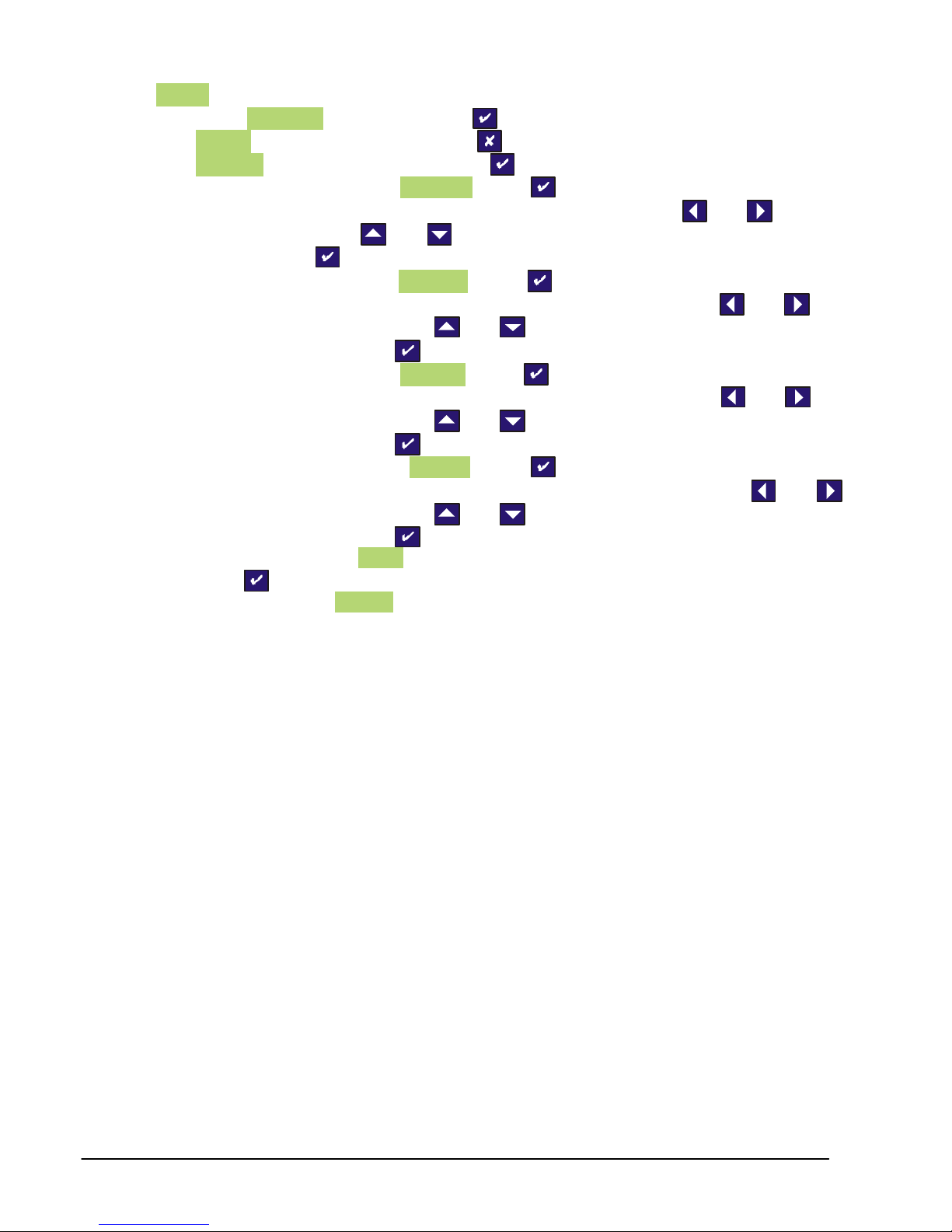
(1) When CALibrAt is displayed press
(2) LiVE ? will now be displayed, press
(3) tAbLE ? will now be displayed, press
(4) You will be prompted with InPut LO , press
(5) Now enter the zero offset sensitivity of the sensor by using the and button to
select a digit and the and buttons to change the digit. When the value has
been set press .If you do not know this, simply enter all zeros.
(6) You will be prompted with dISP LO. Press to enter the display value required for
the low input figure entered. The value can be entered by using the and
button to select a digit and the and buttons to change the digit. When the
value has been set press
(7) You will be prompted with InPut HI, press
(8) Now enter the sensitivity figure supplied for the sensor by using the and
button to select a digit and the and buttons to change the digit. When the
value has been set press .
(9) You then be prompted with dISP HI. Press to enter the display value required
for the high input figure entered. The value can be entered by using the and
button to select a digit and the and buttons to change the digit. When the
value has been set press
(10) You should now see donE displayed. This means the calibration was successful,
press to the 9320 to normal operation mode, with the new calibration data
stored. If you see FaiLEd, then you will need to repeat the calibration, checking that
you have completed the procedure in the correct order, and that the sensor is
connected correctly.
Interface 9320 User Manual Issue 1.0
Page 18
17
Specifications
Lbs
kN
90
34
Performance Input Type: Strain Gauge Full Bridge Sensors
Input Range: Up ±5mV/V (±50mV/V can be supplied, with factory set option)
Non Linearity: ±0.005% FSD
Thermal Drift: <25 ppm/°C
Excitation Voltage: 5Vdc (±4%), 59mA maximum current
Minimum Bridge Resistance: 85O (4off 350O sensors in parallel)
Internal Battery: 2off AA size alkaline, access via sealed rear compartment
Battery Life: 45 hours (Typical 450 hours in low power mode), with 350O sensor
Update Rate: Up to 40mS (can be set in configuration menu)
Indication Display Type: 7½ digit LCD display, 8.8mm high digits
Display Resolution:
Annunciators: Low Battery warning; peak; trough; hold; net; shunt cal; range
Control Variables Front Panel User Keys:
Settable Parameters:
Mechanical Electrical Connection: 5 pin Binder socket (mating plug supplied)
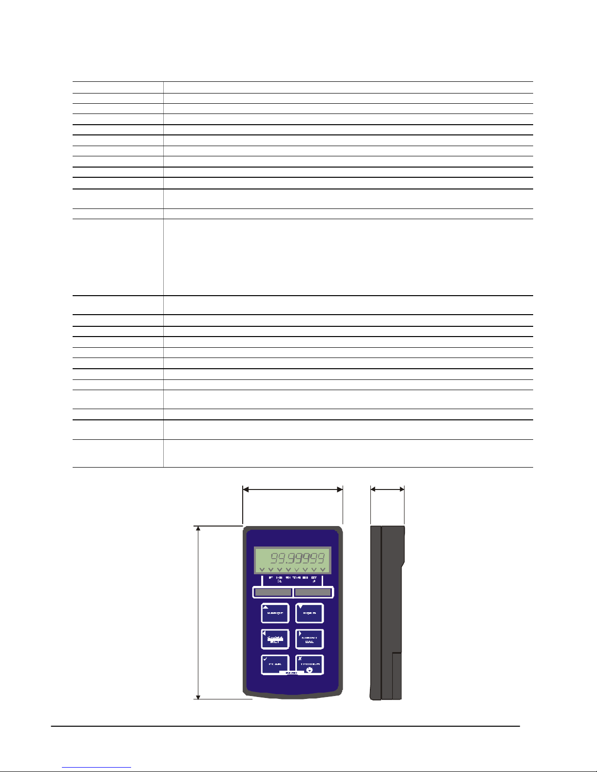
Physical Size: See drawing below
Weight: 260 grams
Legends: Insert legends for engineering unit identification (supplied)
Environmental Operating Temperature: -10°C to +50°C
Environmental Rating: IP65 (when mating plug fitted)
Enclosure Type: ABS, dark grey (Leather Carry Case Optional)
Safety/Low Voltage Directive
EMC Directive EN 50 081 – 1 : 1992 (Light Industrial)
Emissions
EMC Emissions
1 part in 250,000 at 1Hz update rate
1 part in 65,000 at 10Hz update rate
Tactile Keys with recessed rims for:ON/OFF Switches 9320 power on/off
RANGE Selects between two ranges
HOLD Hold the current display value, press again to release
GROSS/NET Zero’s display (±100% range)
SHUNT CAL Generates simulated input for indicator testing
PEAK Enables peak hold
TROUGH Enables valley/trough hold
Tare/Zero value; display resolution/decimal point position; display
update rate; low power mode; auto power off;
73/23/EEC amended by 93/68/EEC To IEC 1010-1:1990, EN
61010 – 1 – 1993 89/336/EEC
EN 50 081 – 2 : 1992 (Heavy Industrial)
pr EN 50 093 : 1991
EN 50 082 – 1 :1992 (Light Industrial)
EN 50 082 – 2 :1992 (Heavy Industrial)
Mechanical Dimensions
Interface 9320 User Manual Issue 1.0
152
kgf
Page 19

18
Warranty
The 9320 is warranted against defective material and workmanship for a period of (1) one year from the date of shipment.
If the Interface, Inc. product you purchase appears to have a defect in material or workmanship or fails during normal use within the period,
please contact us and we will assist you in resolving the problem. If it is necessary to return the product, please request an RMA# and
include a note stating name, company, address, phone number and a detailed description of the problem. Also, please indicate if it is a warranty
repair.
The sender is responsible for shipping charges, freight insurance and proper packaging to prevent breakage in transit.
Interface, Inc. warranty does not apply to defects resulting from action of the buyer such as mishandling, improper interfacing, operation outside
of design limits, improper repair or unauthorised modification.
No other war ranties are expressed or implied. Interface, Inc. specifically disclaims any implied warranties of merchantability or fitness for a
specific purpose. The remedies outlined above are the buyer’s only remedies. Interface, Inc. will not be liable for direct, indirect, special,
incidental or consequential damages whether based on the contract, tort or other legal theory.
In the interests of continued product development, Interface, Inc. reserves the right to alter product specifications without prior notice.
IF 0137 MD 1D Doc No. 517-173
Interface 9320 User Manual Issue 1.0
 Loading...