

Interdata 8/32 Installation Manual

Publication Number 29-526R01
MODEL
(~USTOMER
INSTALLATION MANUAL
8/32
Subsidiary
Oceanport,
of
PERKIN-ELMER
New
Jersey
07757,
U.S.A.
@
INTER
All
Printed
September
DATA
in
INC.,
U.S.A.
1976
Rights Reserved
1976
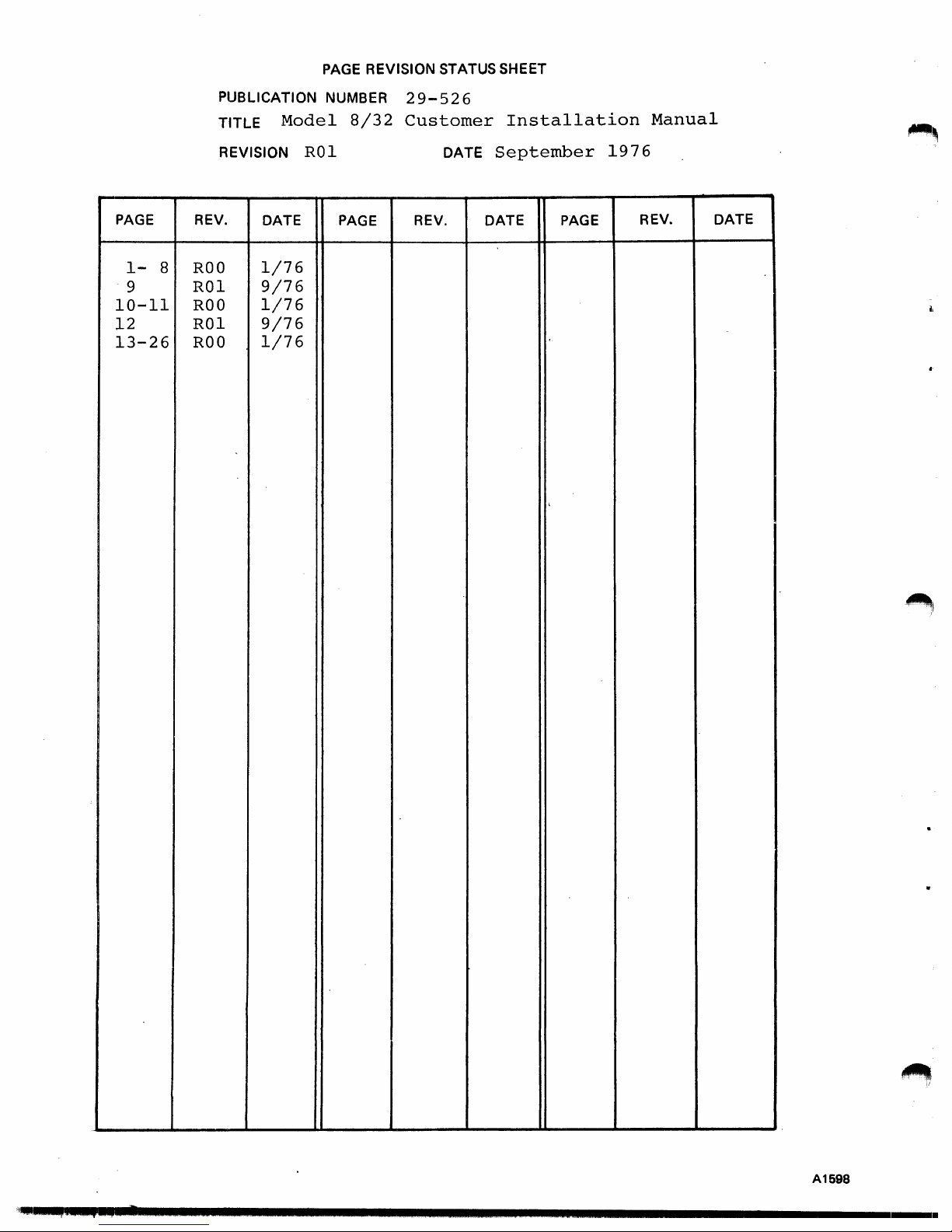
PAGE
REVISION STATUS
SHEET
PAGE
1-
9
10-11
12
13-26
PUBLICATION
TITLE
REVISION
REV.
8
ROO
ROI
ROO
ROI
ROO
DATE
1/76
9/76
1/76
9/76
1/76
Model
RO
NUMBER
8/32
1
PAGE
29-526
Customer
DATE
REV.
Installation
September
DATE
,
PAGE
1976
Manual
REV.
DATE
'.i
..
q~,
.. , ...
~""·
.......................................................................
A1698
1
....
.

1.
INTRODUCTION
2.
UNPACKING
TABLE
..
OF
CONTENTS
3. MECHANICAL
3.1 MECHANICAL COMPONENTS
3.2
4. POWER SUPPLY
4.1
4.2
4.3 POWER SUPPLY/CHASSIS CABLING
5.
PROCESSOR
5.1
5.2 BASIC
5.3
CONFIGURATION
COOLING
INTRODUCTION
MOUNTING
4.3.1
4.3.2
4.3.3
4.3.4
4.3.5
4.3.6
4.3.7
4.3.8
INSTALLATION
PROCESSOR
5.3.1
5.3.3
(SEE
FIGURES 3 THROUGH
INSTALLATION
System
Voltages . . . . .
34-024
System
Power
Control
Primary
Conversion
Adjustments
Configuration . . . . . . . . . . .
Installation
AND EXPANSION CHASSIS
PROCESSOR
35-536
5.3.2
35-537
35-538
Power
Procedure
.............
CONFIGURATION
STRAP
CPA . . .
CPB . . .
ALU
6)
Power
Supply
. . . . . .
Requirements
.
from 115
. . . . . . . . . . . .
OPTIONS
Clock
to
230
INSTALLATION
AND
CABLING.
VAC
.
Operation
1
3
5
5
5
5
5
. 6
6
7
7
7
7
13
13
13
15
15
15
16
..
DISPLAY
6.
7.
MEMORY
8.
CONFIGURATION
9. CABLES
10.
TESTING.
PANEL
INSTALLATION
7.1
FIRST
SECOND MEMORY EXPANSION
7.2
8.1 BASIC CHASSIS
8.2
SYSTEM EXPANSION CHASSIS
8.3
CIRCUIT
8.4
INTERRUPT
8.5
TERMINATORS
8.6
MULTILEVEL
9.1 POWER
9.2
SYSTEM EXPANSION CABLE
9.3
TYPICAL
1 0.1
STANDARD
10.2
ADDITIONAL
INSTALLATION
AND
MEMORY EXPANSION (UP
....
I/O
BOARD
CABLES.
CONFIGURATIONS
. . . . . . .
DISTRIBUTION
PRIORITY
..........
EXTERNAL
TEST
SOFTWARE
.
EXPANSION
BACK
INTERRUPTS
....
SOFTWARE
..
TO
PANEL
512KB)
WIRING
.
CABLING
16
16
16
16
19
19
19
19
19
20
.
. 20
24
24
24
25
25
25
25
29-526
ROO
1/76

FIGURES
~,
Figure
1.
Figure
2.
Figure 3.
Figure 4.
5.
Figure
Figure 6.
7.
Figure
Figure
8.
Figure 9.
Figure 10.
Figure 11. .
Figure 12.
Figure 13.
Figure 14.
Figure 15.
Figure 16.
Figure 17.
Figure 18.
Figure 19.
Figure
20.
Figure 21.
Figure 22.
Figure 23.
Figure 24.
Figure 25.
System Cabinet Physical Dimensions . . . . . .
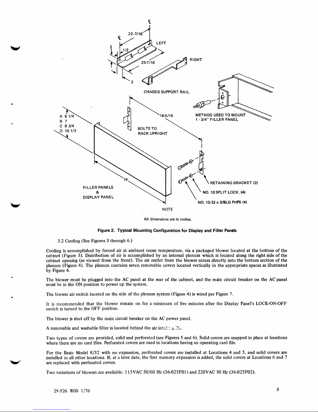
Typical Mounting Configuration for Display and Filler
Enclosure
Enclosure
Blank Cover
. Duct
Wiring
34-024 Power Supply Mounting
Power Control Circuit Diagram
Wiring
for Control
Basic
Model
Model
Model
Model
Writable Control Store Power Distribution
16-398 Half Board
02-234
Basic Processor;
. Basic Processor; Rear
Front
Front
Standard
Modified
Interrupt
Typical
Front
View.
Section View A-A .
(Solid)
Outlet
Cover (Perforated)
of
the
Blower Air Switch
of
the
Second
of
Different AC
8/32
with 128KB Memory Power Distribution
8/32
with 256KB Memory Power Distribution
8/32
with 384KB and 512KB Memory Power Distribution
8/32
Power Wiring for 640KB
8/32
Basic with Double Floating Unit
I/O Adapter (Top View)
Front
View
of
Processor Configuration with First Memory Expansion
View
of
Processor Configuration with First and Second Memory Expansion
Interrupt
Interrupt
Priority with ESELCH Installed .
System Configuration (Back Panel)
. .
Deck
Adapter.
View
View.
Priority.
Priority.
of
the Rotary Switch
Phases.
. . . . . .
. . . . . .
.
.
. . . . .
to
1024KB Power Distribution
and/or
Panels
2
3
4
4
4
4
4
5
6
6
8
9
23
26
10
11
12
14
14
15
17
17
18
21
22
~
TABLE
PROCESSOR CABLES . . . . .
1.
TABLES
. . . . . . . . . . . . . . . . . . . . 15
~I
ii
·~id""""""""""""""""""""""""""""""""""""""""""""""
29-526
ROO
1/76
................
.

MODEL
8/32
CUSTOMER INSTALLATION MANUAL
1.
INTRODUCTION
These specifications provide installation information for INTERDATA Mbde18/32 Digital Systems.
8/32
The INTERDATA Model
user's
exact needs.
describe the
cooling, and the interconnecting cables. Integrated circuit boards are discussed with respect
Circuit descriptions
It
Processor and Expansion chassis, power supply cabling and mounting, filler and Display Panel mounting,
provides the means for convenient expansion
of
these boards are provided in the appropriate maintenance
Digital System features a highly modular structure which permits configuration
NOTE
as
the
user's requirements increase. These specifications
to
or
instruction manuals.
cabling and location only.
to
suit the
The following discussion assumes
standard INTER DATA cabinets.
2.
UNPACKING
To avoid damage
1.
2.
3.
3. MECHANICAL
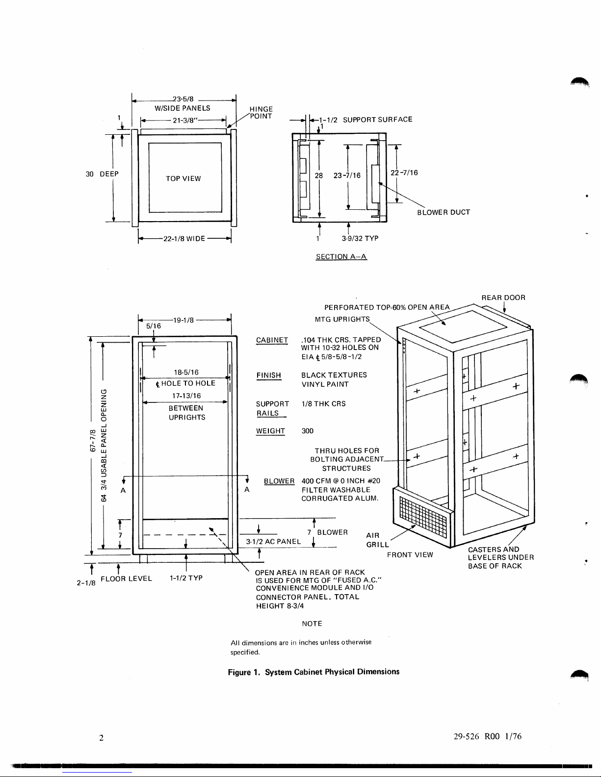
3.1 Mechanical Components
Figures 1
information are provided for
while
the
brackets),
to
the
Model
Carefully remove each
included with
Inspect all components for physical damage.
If
thf~
co'" ,ectors are secured properly.
and 2 illustrate
5Y4
inch, 7 inch, 8% inch,
the
:~maller
the
system
CONFIGURATION
the
3
1
4 inch Filler Panel
that
the
8/32
or
its peripherals, read
component
component.
is
shipped from INTERDATA already rack
mechanical components
the
System Cabinet, Chassis
lOY2
from its carton or crate, observing any special unpacking instructions
inch Filler Panels,
mounts
with spring clips.
the
following procedures before starting an installation.
of
a typical INTERDATA Digital System. Dimensions and mounting
Support
and
equipment
Rails, Display and Filler Panels. Note in Figure 2
the
is
mounted
mounted,
Display Panel
check
to
mount
in
insure
that
all terminals and
the
same way (via retaining
that,
29-526
ROO
1/76
~:.;~8N~
1 I
1-=-21-3/8"---IYPOINT
HINGE
SUPPORT SURFACE
t-
30 DEEP
1
I
c.!)
z
Z
UJ
a..
0
...J
UJ
~
z
r-..
«
I
a..
r-..
(0
UJ
...J
co
«
(/)
:::>
~
M
<::t
(0
TOP VIEW
'-
\'---22-1/8
~19-1/8
I
5/
16
1
•
rr
I
t HOLE TO HOLE
I
-
BETWEEN
UPRIGHTS
+
A
WIDE
18·5/16
17-13/16
~
----l
I
BLOWER DUCT
3·9/32 TYP
SECTION
MTG UPRIGHTS
A-A
PERFORATED TOP·60% OPEN
AREA
I
CRS.
CABINET
I
FINISH
--
I
SUPPORT
RAILS
WEIGHT
,
BLOWER
A
.104
THK
WITH 10-3
EIA t 5/8-
BLACK
VINYL
1/8
THK
300
THRU
BOLTIN
400 CFM @ o INCH
FILTERW
CORRUGA
TAPPED
2 HOLES
5/8-1/2
XTURES
TE
NT
PAl
RS
C
HOLES FOR
G ADJACENT
UCTURES STR
ASHABLE
ALUM.
TED
ON
#20
- -
--
-
1I
I
t t
2-1/8
FLOOR
LEVEL
2
.. ' ...........................................................................................................
--"1.-
•
t I I'\.
I
1-1/2
TYP
f
7 BLOW
~
ER
--
,
,
~
3·1/2 AC PANEL
t
OPEN
AREA
IS
USED FOR MTG
"
CONVENIENCE MODULE
CONNECTOR
HEIGHT
All
dimensions are
specified.
Figure 1. System Cabinet Physical Dimensions
IN REAR OF RACK
OF
"FUSED
PANEL.
8·3/4
NOTE
in
inches unless otherwise
TOTAL
AND
AIR
GRILL
A.C."
I/O
FRONT VIEW
29-526
ROO 1 /76
1
.....
.
~
CHASSIS SUPPORT
~
~
18.5/16· METHOD USED TO
I
o BOLTS
~
RACK UPRIGHT
~'3/4"FILLERPANEL
TO
RIGHT
RAIL
~
~-tt[
MOUNT
I
I
?~a
FILLER
DISPLAY
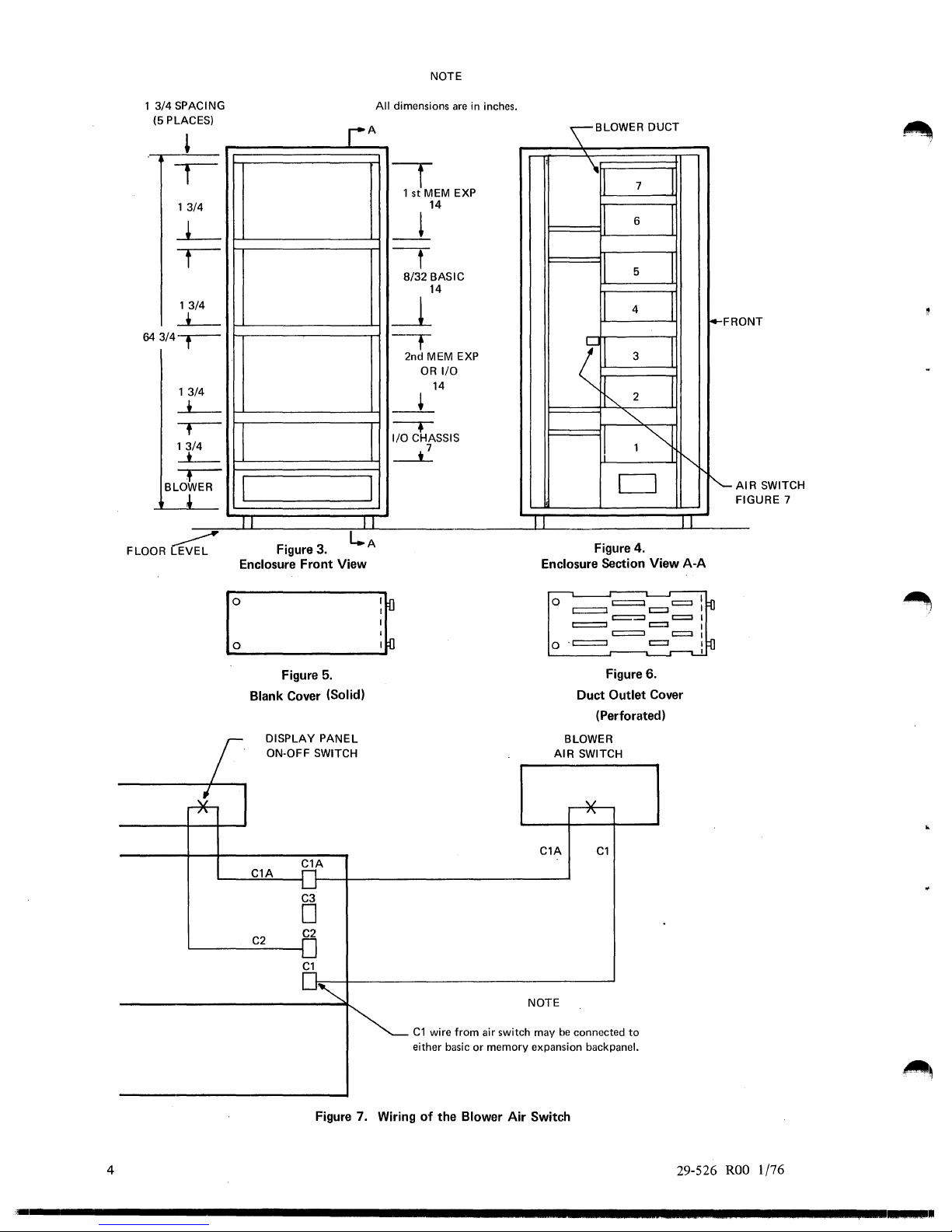
3.2 Cooling (See Figures 3 through 6.)
Cooling
cabine:t (Figure 3). Distribution
cabinet opening (as viewed from the front). The air outlet from the blower enters directly into the bottom section
plenum (Figure 4). The plenum contains seven removable covers located vertically in the appropriate spaces
by Figure 4.
The blower must be plugged into the
must be in the
The blower air switch located on the side
It
switch
The blower
A removable and washable filter
is
accomplished by forced air at ambient room temperature, via a packaged blower located at the bottom
ON
is
recommended that the blower remain on for a minimum
is
turned to the OFF position.
is
shut
PANELS
&
PANEL
All
Figure
2.
Typical Mounting Configuration
of
air
is
accomplished by an internal plenum which
AC
position to power up the system.
off
by the main circuit breaker on the
is
located behind the air int
panel at the rear
of
the plenum system (Figure 4)
NOTE
dimensions
AC
<\
are
in inches.
for
of
the cabinet, and the main circuit breaker on the
of
five
power panel.
••
!:-=:
g,.~~!:.,.
\
RETAINING
\ NO. 10 SPLIT LOCK. {4)
NO. 10·32
Display
is
wired per Figure
minutes after the Display Panel's LOCK-aN-OFF
and
x 3/BLG
Filler
is
BRACKET
PHPS
Panels
located along the right side
7.
14)
(21
as
illustrated
AC
of
the
of
the
of
the
panel
Two types
where there are no card files. Perforated covers are used in locations having an operating card
For
installed in all other locations. If, at a later date, the first memory expansion
are replaced with perforated covers.
Two variations
the
Basic Model
29-526
of
covers are provided, solid and perforated (see Figures 5 and 6). Solid
8/32
with no expansion, perforated covers are installed at Locations 4 and
of
blowers are available: 115VAC 50/60
ROO
1/76
is
added, the solid covers at Locations 6 and 7
Hz
(36-025FOI) and 220VAC 50
.covers
are snapped in place at locations
file.
5,
and solid covers are
Hz
(36·025F02).
3
1
3/4
SPACING
(5
PLACES)
13
/4
13
/4
-L-
64
3/4--r--
13
/4
-L-
,--
13
/4
-*--
,-
ER
BLOW
,
FLOOR~
I
J
Figure
Enclosure Front View
3.
A
r
I
J I
L..A
NOTE
All
dimensions
are
in inches.
\
f
1
st
MEM EXP
14
-!
-t
8/32
BASIC
14
~
-T
2nd MEM EXP 3
OR
I/O
14
-+
-.
I/O
CHASSIS
~
II
Enclosure Section View
BLOWER DUCT
"-
It
II
II
4
I
II
(
2
l I
"'"
1"i
II
D
Figure 4.
7
I
6
I
5
I
I
i4-FRO
NT
I
"-
'"
II
A-A
'-AI
R SWITCH
GURE
FI
7
5.
Figure
Blank Cover (Solid)
DISPLAY
ON-OFF SWITCH
C1A
PANEL
C1A
C3
o
C2
C2
C1
o
o . c:=:::::::J
AIR
C1A
NOTE
C1
wire
from
either basic or memory expansion backpanel.
air switch may
be
c:=::::J
t::::=:=l
Duct
(Perforated)
BLOWER
SWITCH
C1
connected
c::=::::l
r:::::=::::I
c:::::::=:J c::::::l
Figure 6.
Outlet Cover
to
c::::J
c:=:J
c::::J
c::::J
c::::J
Figure
4
'-
............................................................................................
7.
Wiring
of
the Blower
Air
Switch
29-526
ROO
1/76
~
.. I .....
.
4. POWER SUPPLY INSTALLATION
4.1 Introduction
This section describes the installation
provided for the
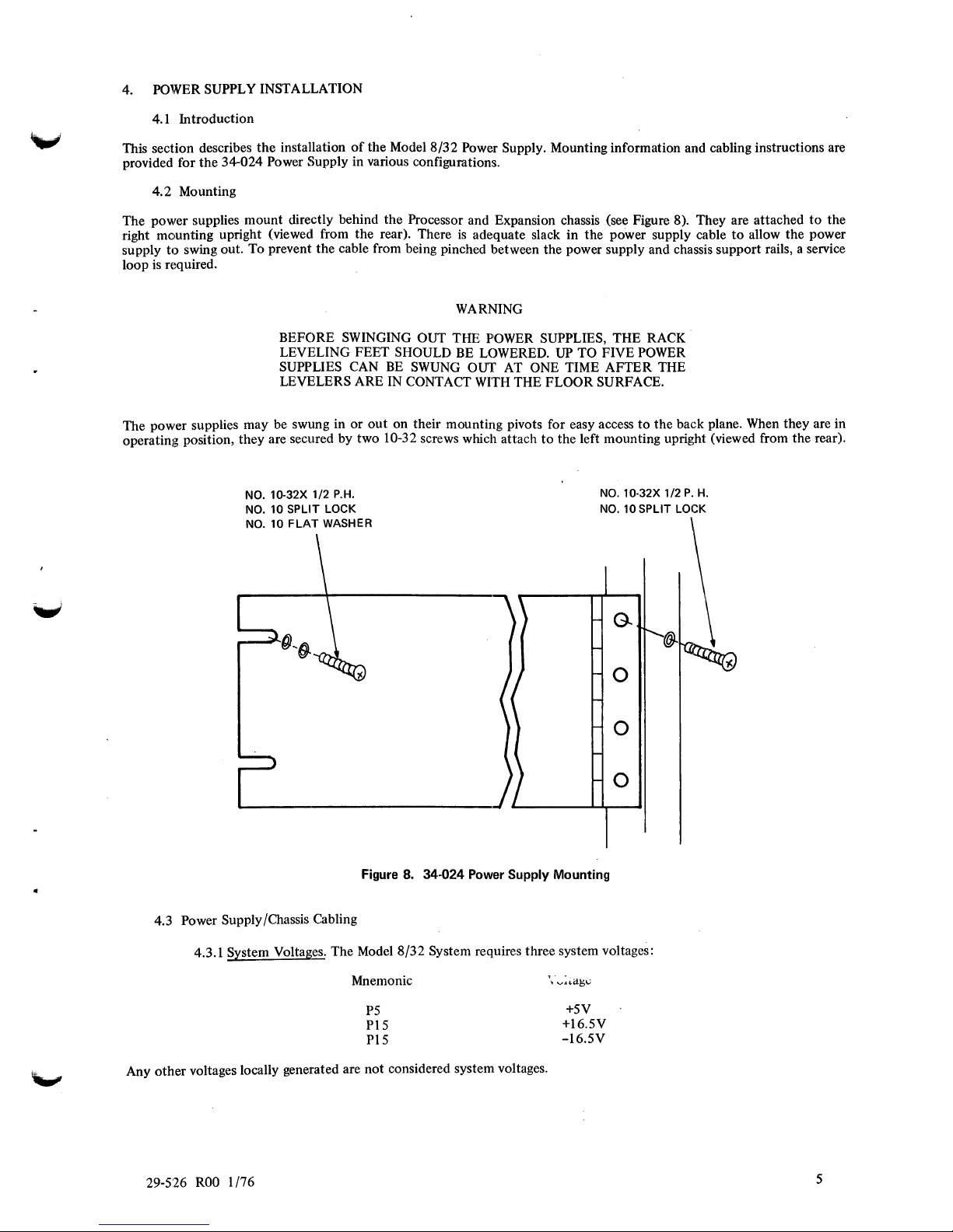
4.2 Mounting
The power supplies mount directly behind the Processor and Expansion chassis (see Figure
right mounting upright (viewed from the rear). There
to
supply
loop
is
required.
The power supplies may be swung in
operating position, they are secured by two 10-32 screws which attach
34-024 Power Supply in various configurations.
swing out. To prevent the cable from being pinched between the power supply and chassis support rails, a service
BEFORE SWINGING OUT THE POWER SUPPLIES, THE RACK
LEVELING FEET
SUPPLIES
LEVELERS ARE IN
NO. 10-32X 1/2
NO.
10 SPLIT LOCK
NO.
10
FLAT
of
CAN
or
P.H.
WASHER
the Model
out
8/32
Power Supply. Mounting information and cabling instructions are
is
adequate slack in the power supply cable
WARNING
SHOULD
BE
CONTACT
on their mounting pivots for easy access
SWUNG
BE
LOWERED. UP TO FIVE POWER
OUT AT ONE TIME AFTER THE
WITH
THE FLOOR SURFACE.
to
the left mounting upright (viewed from the rear).
NO.
10·32X 1/2
NO.
10
to
the back plane. When they are in
SPLIT LOCK
8). They are attached
P.
H.
to
allow the power
to
the
4.3 Power Supply/Chassis Cabling
4.3.1 System Voltages. The Model 8/32 System requires three system voltages:
Mnemonic
Any other voltages locally generated are
Figure
8.
34-024 Power Supply Mounting
P5
PIS
PIS
not
considered system voltages.
o
o
o
+5V
+16.5V
-I6.5V
ROO
29-526
1/76
5
ments in the Model
when normally loaded.
Refer
C2
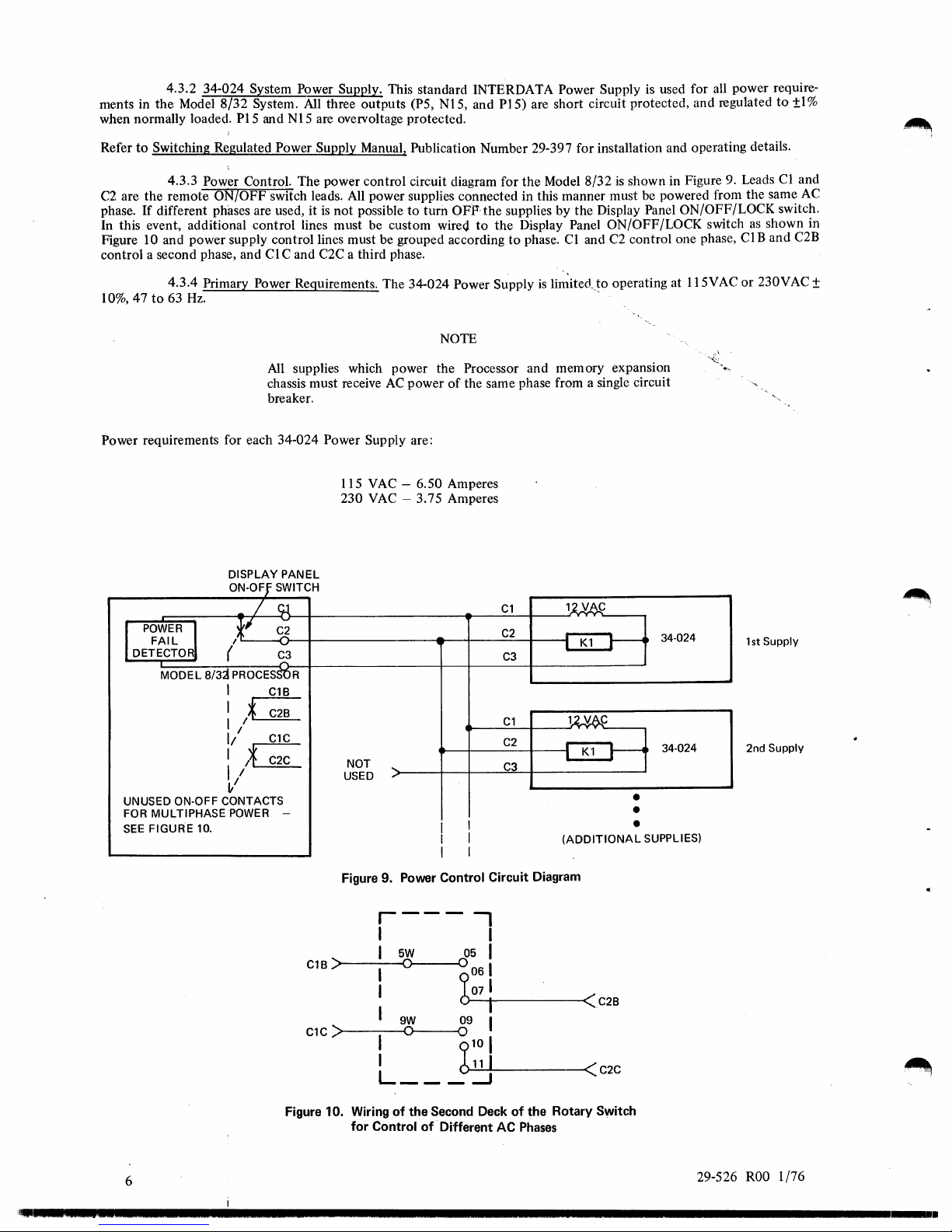
phase. If different phases are used, it
In this event, additional control lines must be custom
Figure
control a second phase, and
4.3.2 34-024 System Power Supply. This standard INTERDATA Power Supply
to
Switching Regulated Power Supply Manual, Publication Number 29-397 for installation and operating details.
4.3.3
are the remote ON/OFF switch leads. All power supplies connected in this manner must be powered from the same
10 and power supply control lines must be grouped according
8/32
System. All three outputs (P5, N15, and
PIS
and N15 are oveIVoltage protected.
Power Control. The power control circuit diagram for
is
not possible
Cl
C and C2C a third phase.
to
turn OFP-the supplies by the Display Panel ON/OFF/LOCK switch.
wire(j
PIS)
to
the Display Panel ON/OFF/LOCK switch
to
are short circuit protected, and regulated
the
Model
8/32
phase. CI and
is
used for all power require-
is
shown in Figure 9. Leads Cl and
C2
control one phase,
CIB
to
as
shown in
and C2B
±I %
AC
10%,47
Power requirements for each 34-024 Power Supply are:
4.3.4 Primary
to
63
Hz.
Power Requirements. The 34-024 Power Supply
All
supplies which power the Processor and memory expansion
chassis must receive
breaker.
DISPLAY PANEL
ON-OFf
SWITCH
AC
power
115 VAC - 6.50 Amperes
230
VAC
- 3.75 Amperes
- /
I
POWER,J
FAIL
DETECTO
MODEL
UNUSED ON-OFF CONTACTS
FOR MULTIPHASEPOWER
SEE
FIGURE 10.
,U
(
8/3j
PROCESS'OR
I
I /
I *
1/
:
/~
~/
C3
.....
C18
C28
C1C
C2C
NOT
....
USED
"
-
Figure 9. Power Control Circuit Diagram
is
li~itedJo
NOTE
of
the same phase from a single circuit
Cl
C2
C3
Cl
C2
C3
I
I
I
I
I
I
(ADDITIONAL
operating at 115VAC
.
11vAj:
.-
I
Kl
~
lU6..C
.-
;
Kl
~
34·024
34-024
•
•
•
SUPPLIES)
or
1st
2nd
230V
Supply
Supply
AC
±
C18
Cl
C
Figure 10. Wiring
6
'~I._
.5
.....
'.'.22.'
••• 2 .....................................................................................................
r---
I I
for
I
I
I
I
I
I
L
Control
)>------<0
)>-----<0
5W
05 I
0
b0
9W
___
of
the Second Deck
09 I
0
910
O..:...11~1L-
of
-Different AC
-,
61
071
-11------<C28
I
___
~
of
the Rotary Switch
Phases
--«
C2C
29-526
ROO
1/76
.
 Loading...