

Intercoax EUP-8401T, EUP-8401R Installation Manual
EUP-8401T / 8401R 설치 가이드 /
Installation Guide
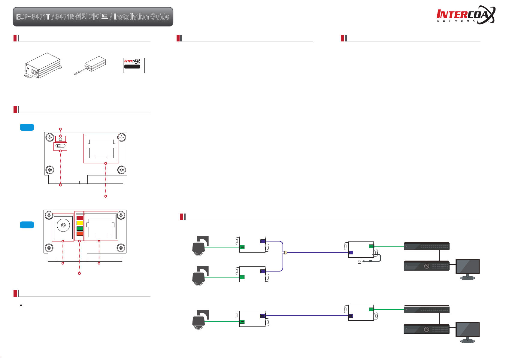
구성품 / Package Contents
EUP-8401T X 1 / 8401R X 1
제품 각 부분의 명칭 / Hardware Overview
Join 버튼
Right
PoE ON/OFF Switch(EUP-8401T Only)
Join Button
PoE ON/OFF 스위치(EUP-8401T 전용)
아답터
PF-560120
RJ-45 connector
X 1
RJ-45 커넥터
설치 가이드
설치 가이드
Installation Guide
제품 설치 가이드
1. 별도의 IP설정이 필요없이 자동으로 카메라에 IP를 부여하는 경우(DHCP 등)를
제외하고, 카메라 제조사 설명서를 참조하여 카메라에 IP주소를 설정해 둡니다.
2. UTP 케이블의 RJ-45 (EoC 라인) 커넥터를 EUP-8401T/8401R에 각각 연결합니다.
3. 56V 전원 어댑터를 EUP-8401T/8401R에 먼저 연결한 후 AC전원
콘센트에 연결합니다.
* 케이블의 종류 및 상태, PoE 카메라의 소비전력(W) 등에 따라 실제 연결 가능한
총 거리가 줄어들 수 있습니다. (7W 카메라의 경우 56V 단일 전원 공급으로
5C-HFBT 최대 1,000m까지 PoE지원.)
* EUP-8401T/8401R 두 제품은 모두 LAN 케이블을 통해 데이터와 전원을 함께
전송합니다. EUP-8401R은 Ethernet 포트를 통해 PoE 입력을 지원하는 제품으로,
PoE 스위치 또는 PoE 인젝터를 사용시 아답터 적용 없이 카메라까지 PoE 전원 공급이
가능합니다. (단, PoE 스위치 전원 용량에 따라 PoE 전송거리는 달라질 수 있습니다.)
4. EUP 제품이 문제 없이 연결된 경우, PWR/Join LED가 켜진 것을 확인합니다.
5. EUP-8401T/8401R이 움직이지 않도록 잘 고정시킵니다.
6. 준비된 UTP케이블(Ethernet 라인)을 이용하여 작동중인 NVR과 EUP-8401R을
먼저 연결하고, 이후 카메라와 EUP-8401T를 연결합니다.
7. PoE IP 카메라를 설치하는 경우, 카메라 쪽 EUP-8401의 PoE 스위치를
ON으로 설정합니다. 별도 전원을 공급받는 IP 카메라를 설치하는 경우,
PoE 스위치를 OFF로 설정합니다.
[노트북 컴퓨터 등을 NVR쪽 EUP-8401R에 연결하여 전 구간의 통신 상태를
확인하기 위한 Ping 테스트를 권장합니다.]
8. NVR에 연결된 모니터를 통해 각 카메라의 영상이 잘 나오는 지 확인합니다.
Product Installation Guide
1. Other than automatic IP setting (i.e. DHCP), set the IP address on the
camera following the camera manufacturer’s manual.
2. Connect RJ-45 connectors of UTP Cable (EoC Line) to each EUP-8401T/8401R.
3. Connect 56V DC power to EUP-8401T/8401R first and then to AC outlet.
* The total distance may vary with the type and condition of cables,
and power consumption of PoE camera. (For example of 7W camera,
one 56V DC power can supply up to 1,000m of 5C-HFBT equivalent to RG6.)
* Both EUP-8401T/8401R send data and power together via UTP Cable .
* EUP-8401R supports PoE input (IEEE802.3at / 25.5W) – No power supply
is required when using PoE Switch or PoE injector. (PoE distance can vary
depending on the power supply capacity of PoE Switch.)
4. When they are connected without any problem, PWR and Join LED are on.
5. Fix up the EUP-8401T/8401R.
6. Connect the UTP (Ethernet line) cable between EUP-8401R and NVR first
and then between EUP-8401T and camera.
7. Turn on the PoE switch on EUP-8401 for PoE IP camera and turn off for IP camera
with additional power supply.
[Ping test is recommended to confirm the whole network.]
8. Check the video signal on the monitor
Left
DC 전원 어댑터
DC Power Jack
Status LED indicator
8401T(PoE output)
8401R(PoE input)
상태 표시등
고객 지원 정보 / Customer Service
고객 지원과 관련된 자세한 정보는 웹사이트에서 확인하실 수 있습니다.
Please visit below website for more detail information.
http://www.intercoax.com
Intercoax Co., Ltd.
TEL : 031-365-3133~4
FAX : 031-365-3135
E-mail : info@intercoax.com
제품 적용 구성도 / Product Application
PoE IP Camera
LAN
PoE IP Camera
LAN
PoE IP Camera
LAN
EUP-8401
EUP-8401
EUP-8401
UTP Cable
UTP Cable
EUP-8401R
56V DC Power Supply
EUP-8401R
LAN
PoE Switch
NVR
LAN
PoE Switch
NVR
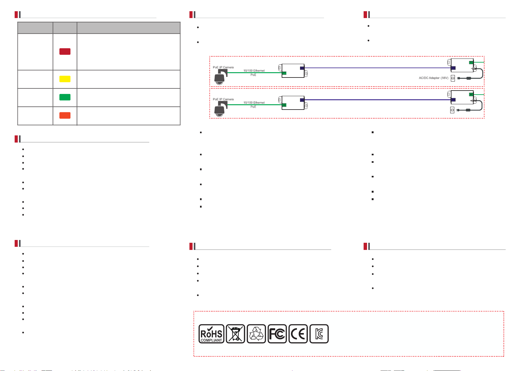
상태 표시등 정보 / LED Indicators
EUP 제품 패스워드 변경 방법
Network Password Change
표시등 색상 상태
PoE-PWR
8401T : PoE 전원 공급 상태
PoE Output
8401R : PoE 스위치를 통해 전원 공급 상태
Power by PoE Switch
Data-Link
Join-Link
데이터 전송시 깜빡임
Data Act
EUP 제품간 링크된 상태
EUP-Product Linked
Power ON
장비 전원 입력 상태
Device Power On
주의사항
설치 가이드의 내용에 따라 순서대로 설치해 주세요.
감전의 위험이 있으니 젖은 손으로 제품과 케이블을 만지지 마세요.
제품이 충격을 받거나, 물기 및 습기가 있는 곳은 설치를 삼가해주세요.
통풍이 잘 되는 곳에 제품을 설치해 주시고, 히터 및 가스렌지 등의 가열성 제품
근처에 설치를 삼가해주세요.
본 제품은 실내 용도로 설계되어 있으니, 실외에서 사용하지 마세요.
제품 고유 용도 외의 다른 용도로 사용하지 마세요.
예) EoC 라인 (당사 장비간 연결되는 UTP 케이블)에 일반 Network 장비 연결 등
제품을 분해 및 개조하지 마시고 페인트를 칠하거나 스티커를 부착하지 마세요.
제품에 이상이 생겼을 경우, 즉시 전원 플러그를 빼고 구입처에 문의하세요.
본 제품은 반드시 56V DC 정격 전원 어댑터와 함께 사용하시기
전원 어댑터는 반드시 제품에 먼저 연결하신 후 AC 전원 콘센트에
바랍니다.
연결해 주세요.
Caution
Please install the device following the installation guide.
Do not touch the device and cable with wet hands.
Keep away from moisture and shock.
Do not install near any heat sources such as radiators, heat registers,
stoves or other apparatus that produce heat.
Indoor use only.
Do not use for other purposes.
i.e. Connectiong Network camera to EoC Line (UTP cable between EoC devices)
Do not disassemble or modify this device.
Do not put any sticker or paint on it.
If this device is defective or malfunctioning, please unplug the power
adapter immediately and contact dealer or service center.
Use only rated 56V power adapter specified by the
manufacturer.
Connect DC power to EUP-8401R first and then to AC outlet.
모든 EUP 제품은 공장출하 시 동일 패스워드로 설정되어 있어, 연결하기만
하면 바로 작동하도록(Plug & Play) 구성되어 있습니다.
다수의 1:1 연결시 각 그룹별 패스워드를 설정하면 만일의 경우 발생할 수
있는 네트워크의 혼선을 피할 수 있습니다.
Group A
EUP-Series
Group B
EUP-Series
1. 기본 연결
편리한 작업을 위해 짧은 UTP케이블을 준비합니다. 준비한 케이블로
EUP 제품을 연결하고 전원 어댑터를 연결합니다.
2. Unjoin 방법: 기존 패스워드 해제
가는 핀을 이용해 한쪽 Join 버튼을 11초 동안 눌러줍니다.
Join LED가 소등됩니다.
이후 다른쪽 Join 버튼을 11초 동안 눌러줍니다.
3. Join 방법: 신규 패스워드 부여
위 2에서 unjoin된 상태에서 한쪽 Join 버튼을 2초 동안 눌러줍니다.
PWR LED 점멸 후 다시 Join LED가 점등됩니다.
이후 다른쪽 Join 버튼을 2초 동안 눌러줍니다.
PWR LED 점멸 후 두 제품의 Join LED가 깜빡이며 제품간 통신이
다시 이루어집니다.
4. 다른 그룹도 위 1~3의 방법을 반복합니다.
[주의사항] 신규 생성된 패스워드는 랜덤으로 자동 부여되며,
공장출하 시 패스워드로 복구할 수 없습니다.
품질 보증
본 제품은 자사의 철저한 품질 관리와 정밀 검사에 합격한 제품입니다.
설치 가이드에 명시된 내용에 따라 설치 및 사용해주시기 바랍니다.
본 제품의 보증기간은 구입일로부터 24개월입니다.
보증기간 내에 제조상 결함이나 고장이 발생하였을 때에는 구입처에
문의하시면 무상 A/S를 받으실 수 있습니다.
보증기간 중 사용자의 고의나 과실 및 개조로 인해 사용이 불가능한 경우와 화재,
지진, 낙뢰 등 천재지변으로 인한 고장의 경우 유상 A/S만 가능합니다.
All EUP products have the same network password on factory
default to support plug & play between EUP Series.
In case of multiple 1:1 connections, It is possible to avoid
network interference by setting password of each group.
UTP Cable
UTP Cable
1. Basic connection
Prepare a short UTP cable for convenience.
Connect EUP products and power adapter.
2. Unjoin : removing the password
Push the join button for 11 seconds. Join LED turns off.
Push the join button for 11 seconds on the other side.
3. Join : making new password
After unjoining, push the join button for 2 seconds.
PWR LED turns off and on, and then Join LED turns on.
Push the join button for 2 seconds on the other side.
After PWR LED is on, Join LED on both side are flickering and
the network is working again.
4. Repeat above 1~3 for the other groups.
EUP-Series
EUP-Series
[Caution] New and random password is automatically assigned and
it can not be restored to the factory default password.
Warranty
This device has passed the quality control and product inspection.
Please install and use according to the installation guide.
The warranty period for this product is 24 months from the date of
purchase.
Any damages or breakage from user's abuse, accident, modification
or natural disasters will not be covered manufacturer's warranty.
INFORMATION TO THE USER
This equipment has been tested and found to comply with the limits for a Class A digital device, pursuant to part 15
of the FCC Rules. These limits are designed to provide reasonable protection against harmful interference when the
equipment is operated in a commercial environment. This equipment generates, uses, and can radiate radio frequency
energy and, if not installed and used in accordance with the instruction manual, may cause harmful interference to
radio communications. Operation of this equipment in a residential area is likely to cause harmful interference in
which case the user will be required to correct the interference at his own expense.
WARNING
Any changes or modifications not expressly approved by the manufacturer could void the user’s authority to
operate the equipment.
 Loading...