

Page 1
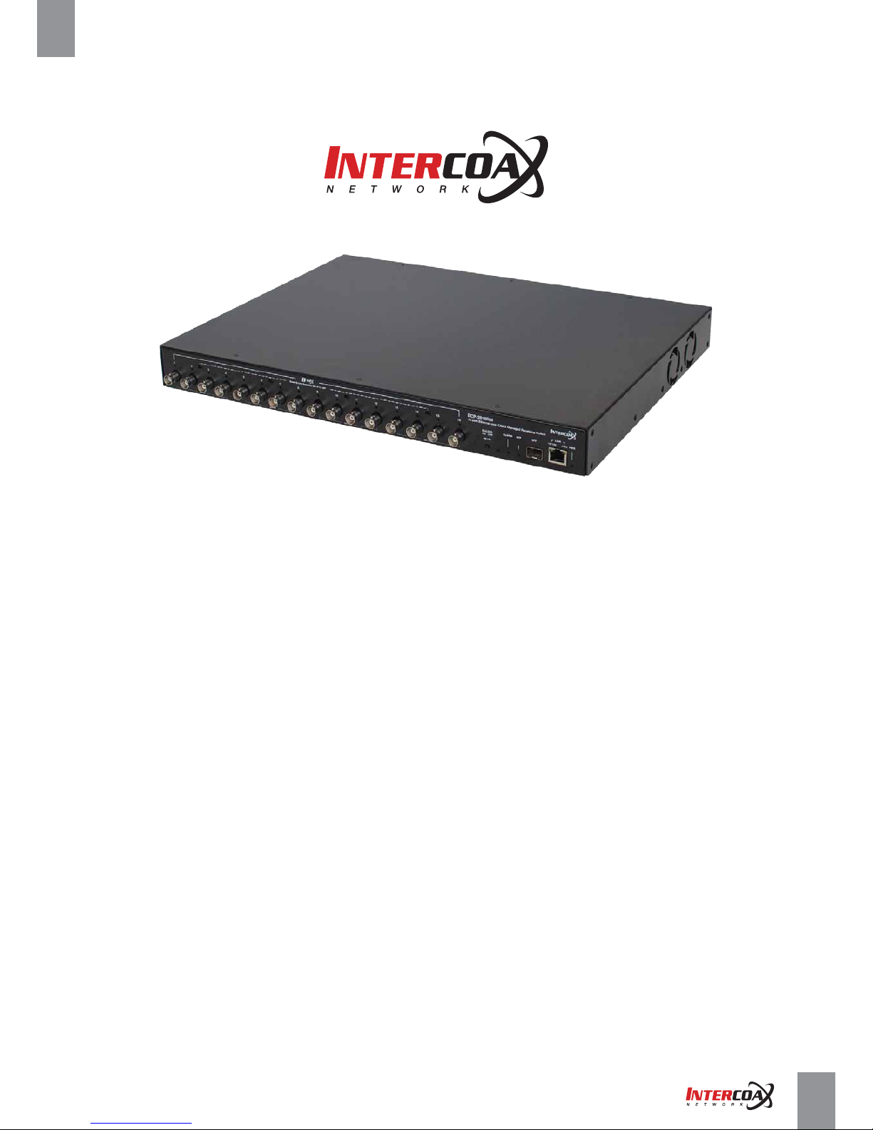
User Manual
version 1.7
Ethernet over Coax / UTP Managed Receiving Switch
ECP-2808RM / ECP-2816RM / EUP-2808RM / EUP-2816RM
Network Solution Provider
High-Speed, Long distance Ethernet and PoE Extender
Page 2

Network Solution Provider
High-Speed, Long distance Ethernet and PoE Extender
Contents
Precaution and Safety Guidelines
1. Product Overview
2. Hardware Installation
3. Product Specifications
4. Management Software Configuration
5. Troubleshooting
6. Warranty Policy
7. Regulatory and Certificates
8. Customer supports
1 - 1. Introduction
1 - 2. Features
1 - 3. Package Contents
2 - 1. Front Panel
2 - 2. Rear Panel
2 - 3. LED Indication
2 - 4. Configuration Instruction
2 - 4 - 1. Prepare devices and materials
2 - 4 - 2. Hardware installation
2 - 4 - 3. Joining instruction
2 - 4 - 4. Label the configured network group
2 - 5. Transmission distance & Bandwidth by distance
2 - 6. Typical In
stallation
3 - 1. Technical Specifications
4 - 1. Overview
4 - 2. System Requirements
4 - 3. Getting started
4 - 3 - 1. ECP MANAGER LITE
4 - 3 - 2. ECP MANAGER
4 - 4. Configuration Windows
4 - 4 - 1. System Summary
4 - 4 - 2. General Window
4 - 4 - 2 - 1. Easy View
4 - 4 - 2 - 2. List View
4 - 4 - 2 - 3. Receiver Overview
4 - 4 - 2 - 4. Join & Node Control
4 - 4 - 2 - 5. Node Monitor
4 - 4 - 2 - 6. Power
4 - 4 - 2 - 7. Multicast
4 - 4 - 2 - 8. Settings
4 - 4 - 3. ECP Config Window
4 - 4 - 3 - 1. Group Configuration
4 - 4 - 3 - 2. ECP Configuration
4 - 4 - 4. SNMP Window
4 - 4 - 5. Admin Window
4 - 4 - 5 - 1. Administrator
4 - 4 - 5 - 2. System Config
4 - 4 - 6. Logout Window
5 - 1. Hardware
5 - 2. Software
17
18
21
39
41
3
4
5
6
7
8
13
15
16
40
Page 3
Network Solution ProviderPage 03 of 41
High-Speed, Long distance Ethernet and PoE Extender
Precaution and Safety Guidelines
• Please install the device following the installation guide.
• Reed all warnings.
• Warning - Do not touch the device and cable with wet hands.
• Warning - Clean this apparatus only with a dry cloth.
• Warning - Please do not put the products on anything electrical conductive (screwdrivers, coins, iron, etc.)
and not put them around water.
• Warning - Do not install near any heat sources such as radiators, heat registers, stoves
or other apparatus that produce heat.
• Warning - Do not use for other purposes.
• Warning - Do not put the signal lines (Coax, UTP) in the same conduit as high voltage wiring
• Do not put any sticker or paint on it.
• Indoor use only.
• Please use only attachments or accessories specified by the manufacturer.
• Unplug the device during a lightning storm or when the device is not used for a long time.
(i. e. Connecting analog camera to BNC connector)
• Do not connect analog cameras to BNC connectors(B-Linx Port) on this devices (ECP Series only)
• Do not connect any IP devices to RJ45 connectors (T-Linx Port) on this devices (EUP Series only)
• When the unit is not working properly, please contact dealer or customer service.
• Please do not disassemble the unit by yourself.
• If this device emits smoke, abnormal noise, or a strange odor, please turn off
the power switch, unplug the AC power cord immediately, and contact dealer or customer service.
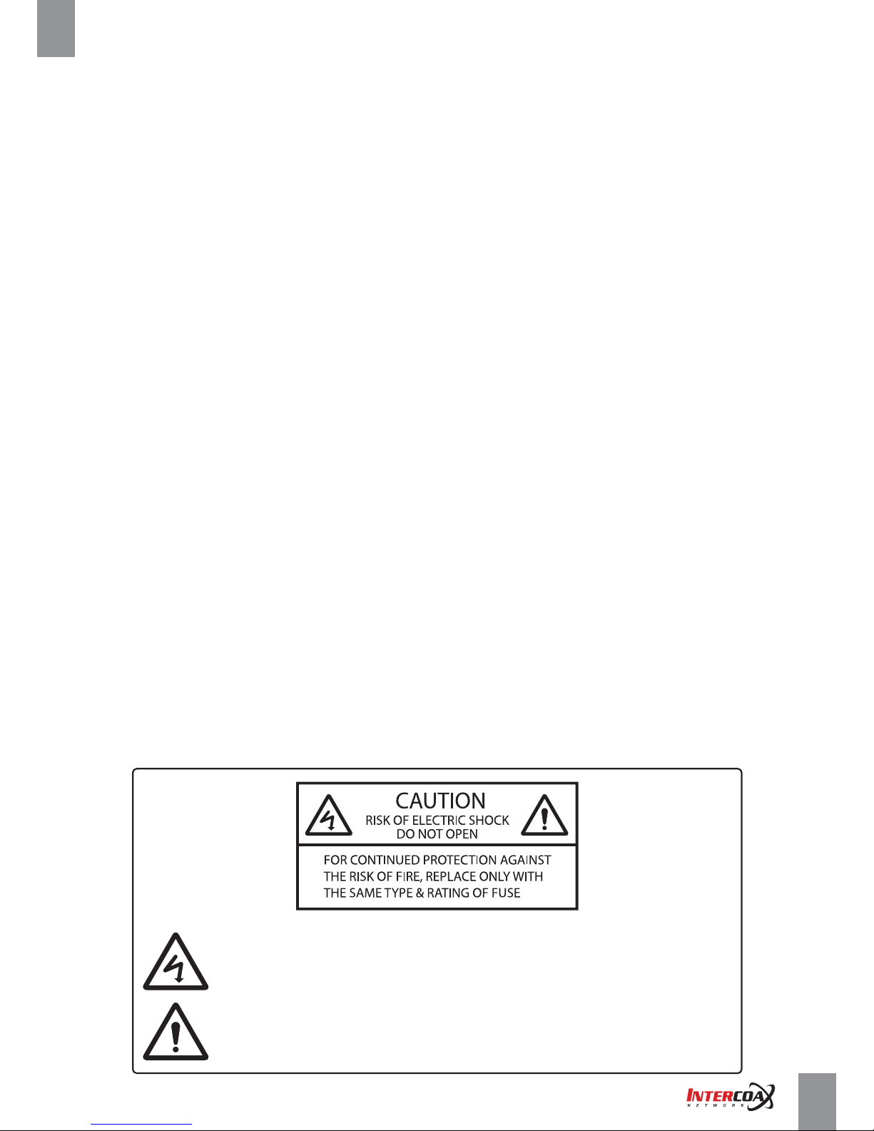
The lightning flash with arrowhead symbol within an equilateral triangle, is intended
to alert the user to the presence of uninsulated “dangerous voltage” within
the product’s enclosure that may be of sufficient magnitude to constitute a risk
of electric shock to persons.
The exclamation point within an equilateral triangle is intended to alert the user
to the presence of important operating and maintenance (servicing) instructions
in the literature accompanying the product.
Page 4
Network Solution ProviderPage 04 of 41
High-Speed, Long distance Ethernet and PoE Extender
1. Product Overview
1-1. Introduction
The All-New Intercoax ECP/EUP-2808RM/2816RM Series is 19” rack mountable managed Long Distance Ethernet
and PoE over Coax/UTP Receiving Switches.
ECP/EUP-2808RM/2816RM series are capable of connecting more than 8/16 ECP Transmitters even
with Daisy-Chain connection and also support PoE powered devices such as IP cameras.
Data rates up to 1Gbps are achievable, making these devices the ideal choice in new or legacy installations
where existing Coax/UTP cable is re-deployed as part of an upgrade from Analog to IP cameras.
ECP/EUP-2808RM series have built-in 320 Watt power supply and ECP/EUP-2816RM series
have built-in 640 Watt power supply (*Dual power supply of 320W + 320W for power sharing and redundancy)
PoE up to 60W per port is available.
Browser based GUI manages all connected IEEE1901-HPAV standard devices.
Furthermore, the world first innovative “Intercoax ECP Manager”software allows managing multiple
of ECP/EUP-2808RM/2816RM series remotely from the central management office
• Ethernet & PoE transmission over Coax / UTP cable
• Complies to IEEE1901-HPAV standard
• Extended transmission distance up to 2,400m
• PoE/ PoE+/ Extra PoE up to 60W (PoE++) per B-Linx port & T-Linx port
• Total management software, “Intercoax ECP Manager", supported
• Friendly Graphic User Interface with EasyView
• Remote Join & Unjoin, Change joining password
• Remote power reset by each port
• Real-time monitoring of power consumption for each port
• Multicast Setting with IGMP Query & Report Generator
• SNMP ready
• VLAN ready
• Port Locking for for extra secured network connectivity
• Alarm LED & buzzer and notification on ECP Manager
• Scheduled event reporting and alert reporting to designative users
• Back up & Restore of configuration
• Auto Power Short Protection
• B-Linx & T-Linx Smart Device Detection for safe power transmission
• 320W (8 port) / 640W (16 port) Built-in Power Supply
• Built-in crosstalk canceling technology
• Support multiple configuration (Daisy Chain, Star, Ring, Etc.) on each port
• Gigabit SFP and Copper uplink port
• 19-inch(1U) rack mountable design
1-2. Features
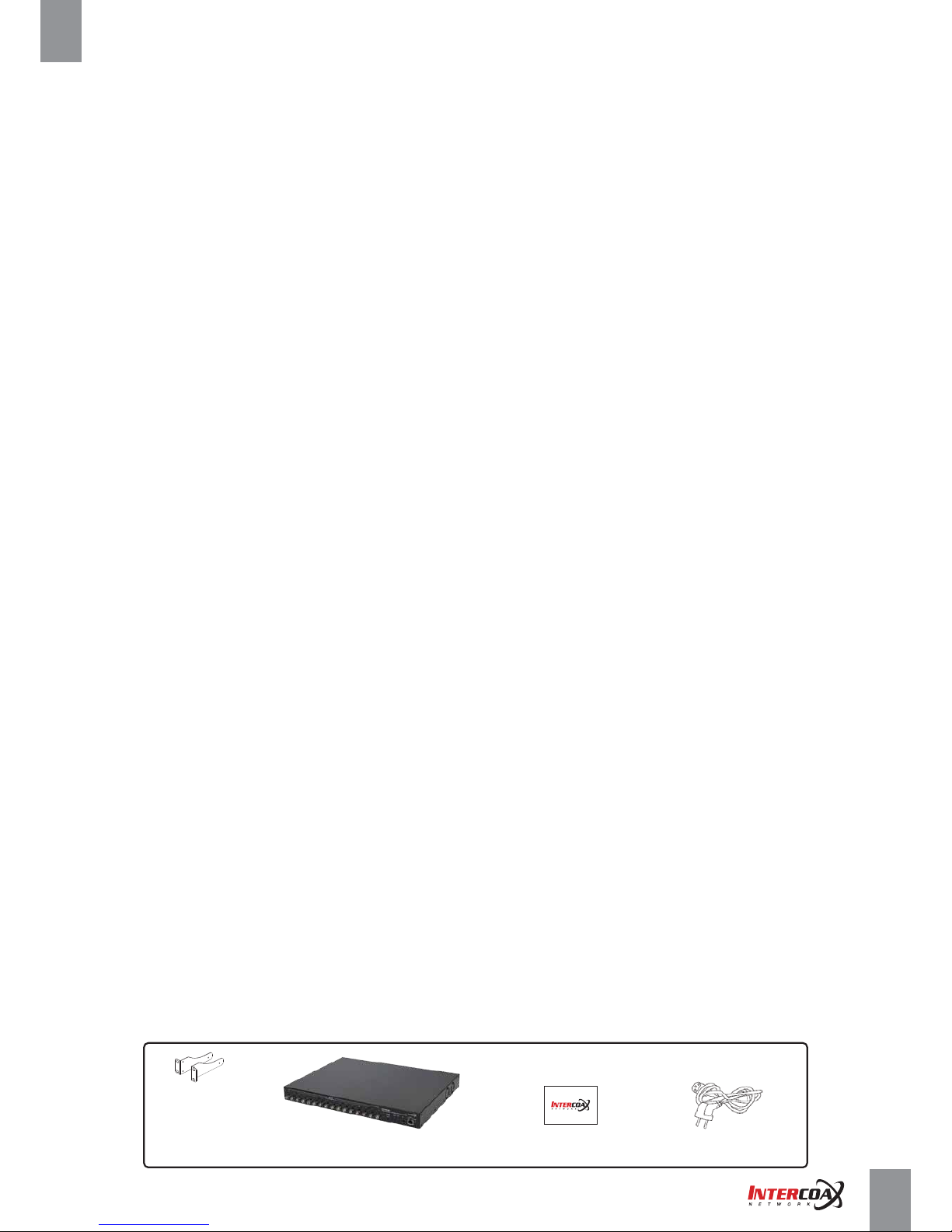
1-3. Package Contents
Bracket
AC Power code
ECP-2816RM
(ECP-2808RM / EUP-2808RM / EUP-2816RM)
Quick Installation Guide
Page 5
2
4
3
5
6 7 8
5
6 7 8
5
6 7 8
1
2
1
5 6
3
3
3
4
4
4
7 8
Network Solution ProviderPage 05 of 41
High-Speed, Long distance Ethernet and PoE Extender
2. Hardware Installation
2-1. Front Panel
EUP-2816RM
ECP-2816RM
EUP-2808RM
ECP-2808RM
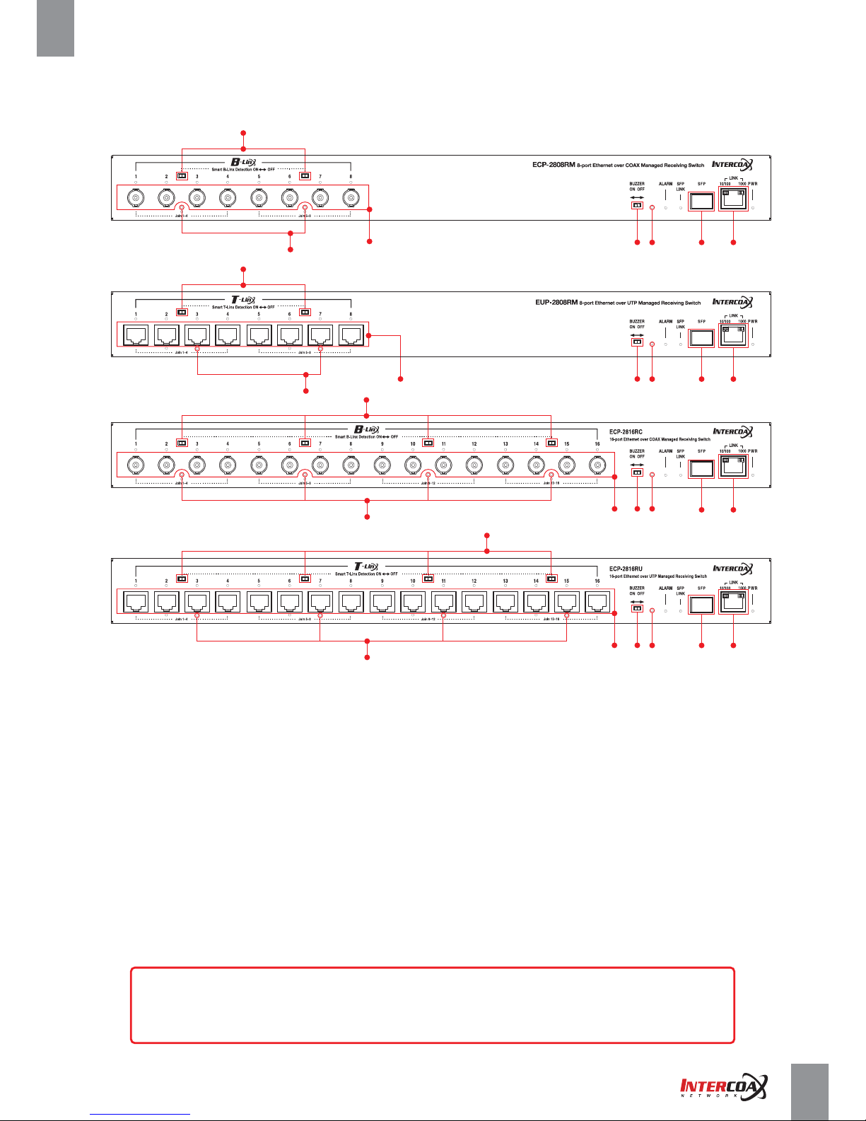
1. B-Linx Ports (1~8 / 1~16) :
Connect Intercoax ECP Transmitters or IEEE1901-HPAV standard devices by coaxial cable with BNC male connector.
2. T-Linx Ports (1~8 / 1~16) :
Connect Intercoax ECP Transmitters or IEEE1901-HPAV standard devices by UTP cable with RJ45 male connector.
3. Smart B-Linx / T-Linx Detection On <-> Off :
B –Linx / T-Linx Detection mode On/Off switch
Detection Mode ON: Detects B-Linx & T-Linx devices before supplying power over Coax.
Detection mode OFF: By-pass detection, classification and power management checks
[Caution]
Do not connect analog cameras or network devices on BNC or RJ-45 port directly if Smart
B-Linx / T-Linx detection switch is OFF, it may cause a serious damage to the device connected.
Page 6
Network Solution ProviderPage 06 of 41
High-Speed, Long distance Ethernet and PoE Extender
2
INPUT: 100~240VAC 50/60 Hz 5A
Model : ECP-2816RM
Default IP : 192.168.4.17
Intercoax Co., Ltd
www.intercoax.com
MAC Address #1
MAC Address #3
H/W Version 1.01
MAC Address #2
MAC Address #4
Serial Number
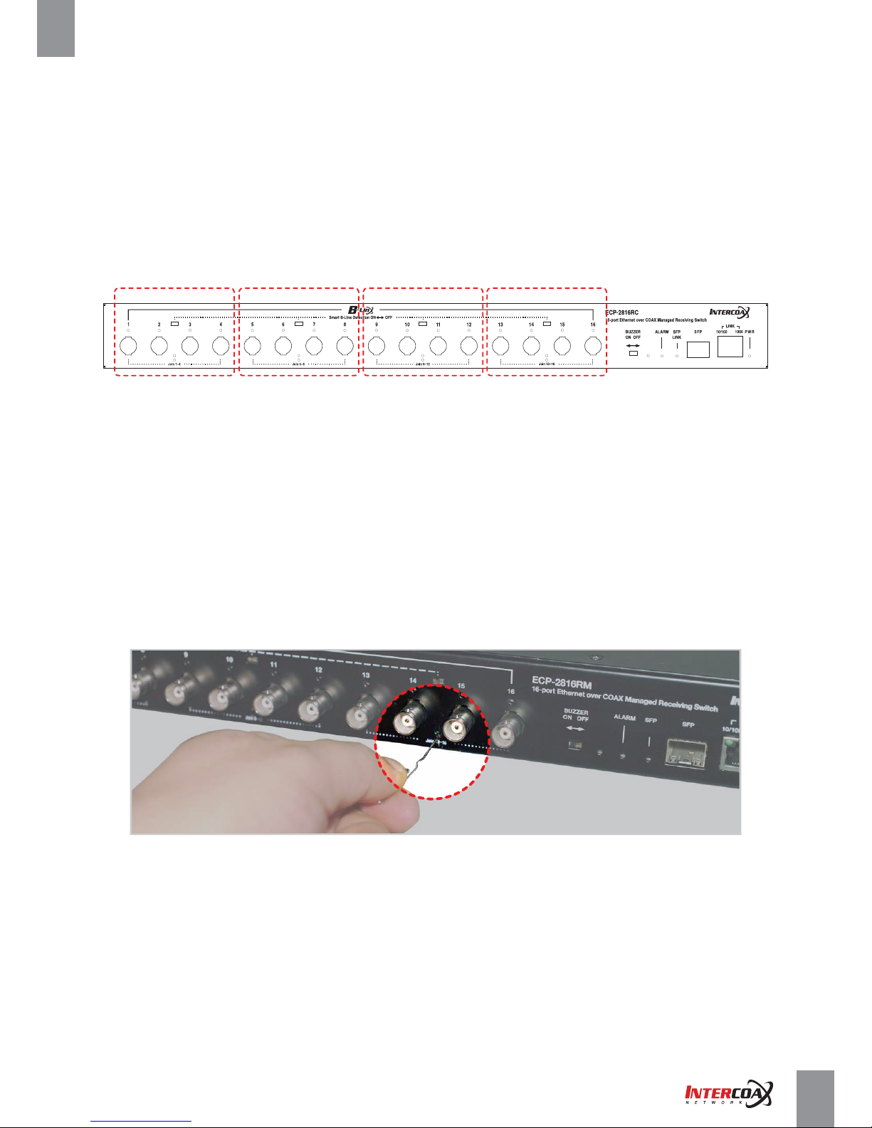
4. Join (1-4, 5-8, 9-12, 13-16) :
Hidden button to create new Network group with ECP Transmitters
- Press the button with a paper clip and hold for 2 seconds for Joining (Create new password)
- Press the button with a paper clip and hold for 15 seconds for Unjoining (Remove the existing password)
※ Please note the joining instruction on Page 11
5. Buzzer On <-> Off :
Move the switch left or right to buzzer sound on or off.
6. Factory Reset :
The hidden factory reset button
Press and hold for 10 seconds the reset button to restore to its original factory settings.
7. SFP :
Connect an SFP module for uplink data (1000 Base-FX GBIC slot)
8. Link :
Connect an RJ45 Ethernet cable for uplink data (10/100/1000 BaseT)
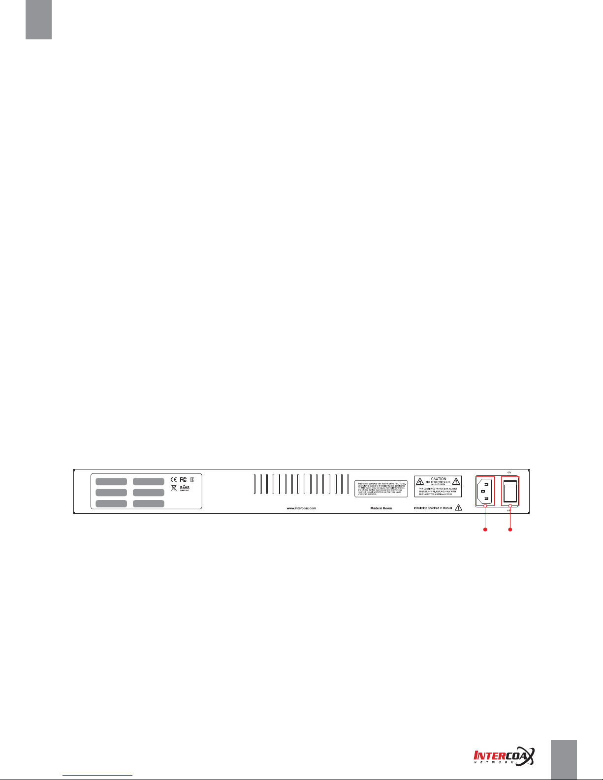
2-2. Rear Panel
1. Power ON/OFF Switch
2. Power Connector
The connector is for 100~240V AC power inputs 50Hz/60Hz
1
Page 7
Network Solution ProviderPage 07 of 41
High-Speed, Long distance Ethernet and PoE Extender
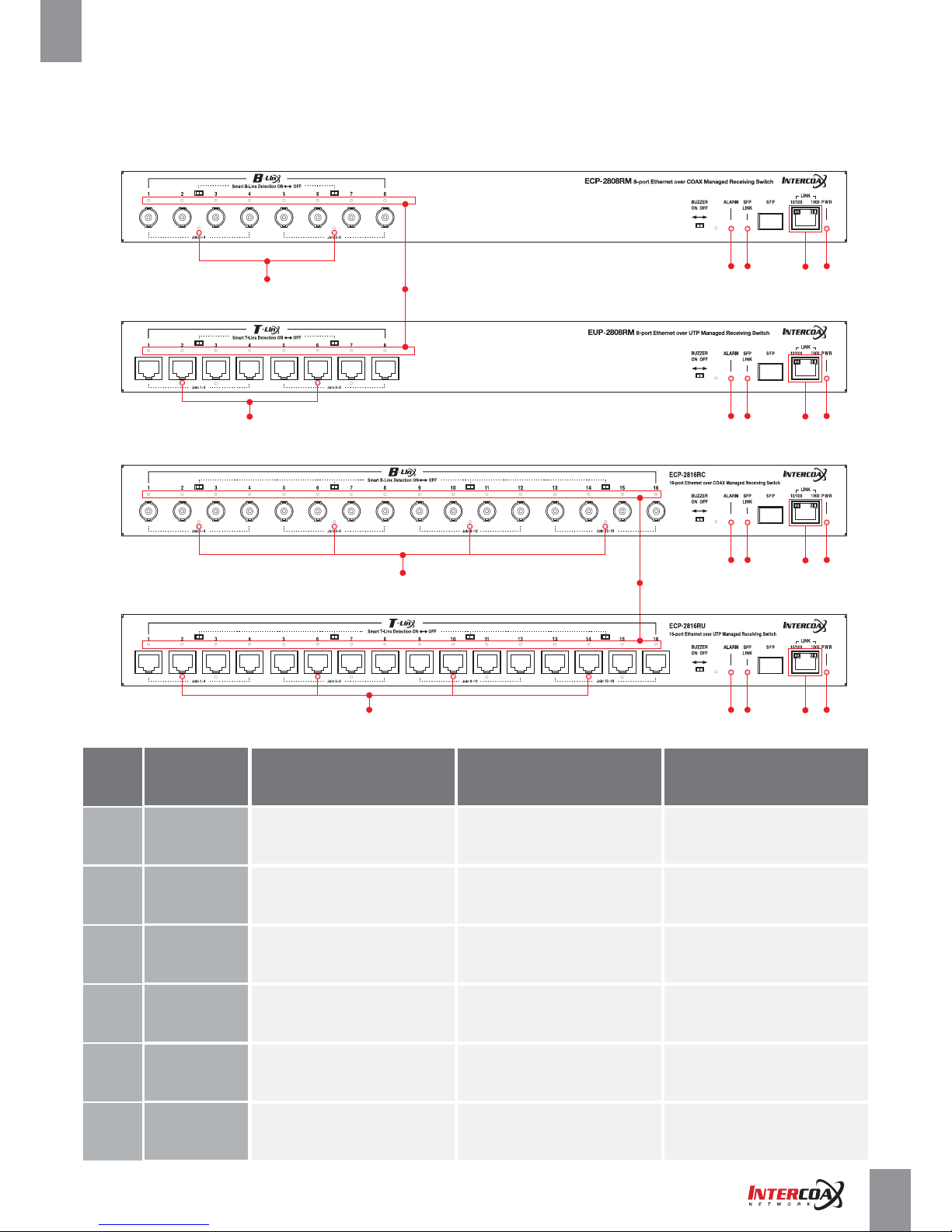
2-3. LED Indication
EUP-2816RM
2
ECP-2816RM
2
1
3 4 6
5
3 4 6
5
EUP-2808RM
2
ECP-2808RM
2
1
3 4 6
5
3 4 6
5
NO
1
2
3
4
5
- Short circuit or over current
protection is working
- ECP/EUP
transmitter linked properly
- Transmitting Data Via Coax / UTP
- Factory reset is progressing
Blinking
- Transmitting Data
Green: 10/100
Amber: 1000
- No device connected
on B-Linx / T-Linx port
- Unjoined ECP device is connected
- Device in normal operation
- SFP Link is down
- No device connected on SFP port
Off
- Uplink (Copper) is down
- Power OFF
6
B-Linx / T-Linx
(1~8 / 1~16)
Join
(1~4 / 5~8,
9~12, 13~16)
Alarm
SFP Link
LED Indication
LINK
PWR
On
- ECP/EUP Transmitter is connected
- Power over coax / UTP
working properly
- System boot-up
- Alarm is detected
- Transmitting Data
- Power ON
•
•
•
•
Page 8
Network Solution ProviderPage 08 of 41
High-Speed, Long distance Ethernet and PoE Extender
2-4. Configuration Instruction
2-4-1. Prepare devices and materials
• Ethernet over Coax /UTP Receiving Switch (ECP-2808RM, EUP-2808RM, ECP-2816RM, EUP-2816RM)
• ECP-Transmitters (ECP-2801, ECP-2701, ECP-9501, ECP-8401, ECP-8301, EUP-2801, EUP-8401,etc)
• EUP-Transmitters (EUP-8401T, EUP-2601T, EUP-2801T & All ECP-Transmitters with BTE-02)
• RJ-45 patch cord
• Short Coax cable or 4 pairs UTP cable (at least 4 cables for joining)
• Password label (if it is necessary)
• Paper clip (If it is necessary for pressing joining button)
• Network Switch and PC (OS: Window 7 or later)
2-4-2. Hardware Installation
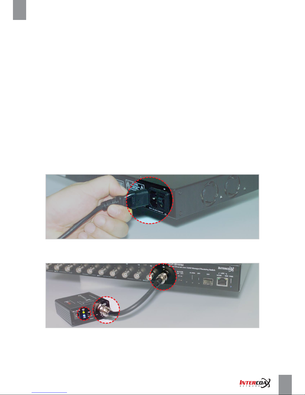
1. Apply power to the receiving switch
2. Use short coax or UTP cables to connect the receiving switch and the ECP/EUP-Transmitters
3. The blue power LED and B-Linx & T-Linx LED of the receiving switch will be ON.
4. The blue power LED of the ECP/EUP-Transmitters will be ON.
Page 9
Network Solution ProviderPage 09 of 41
High-Speed, Long distance Ethernet and PoE Extender
5. The green join LED of the receiving switch and ECP-Transmitters will blink regularly if both devices are already joined
with same network password.
6. If the green Join LED is OFF on both receiving switch and ECP-Transmitter, joining work should be necessary
for network communication.
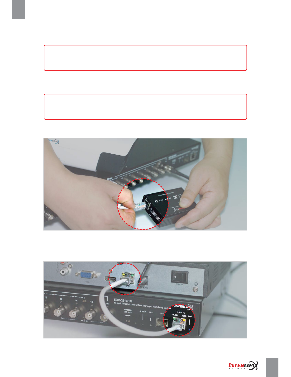
7. Connect ECP-Transmitters to IP Camera
( IP it is PoE IP Camera, Please select PoE Switch ‘ON’ from ECP Transmitters)
8. Connect the receiving switch to Network switch and PC using RJ45 Patch cord.
[Note]
All ECP/EUP products have the same network password as factory default mode
to support plug & play configuration between ECP/EUP Series.
[Note]
For joining work, please refer to the joining instructions on page 11.
Page 10
Network Solution ProviderPage 10 of 41
High-Speed, Long distance Ethernet and PoE Extender
Rackmount Bracket Installation Guide
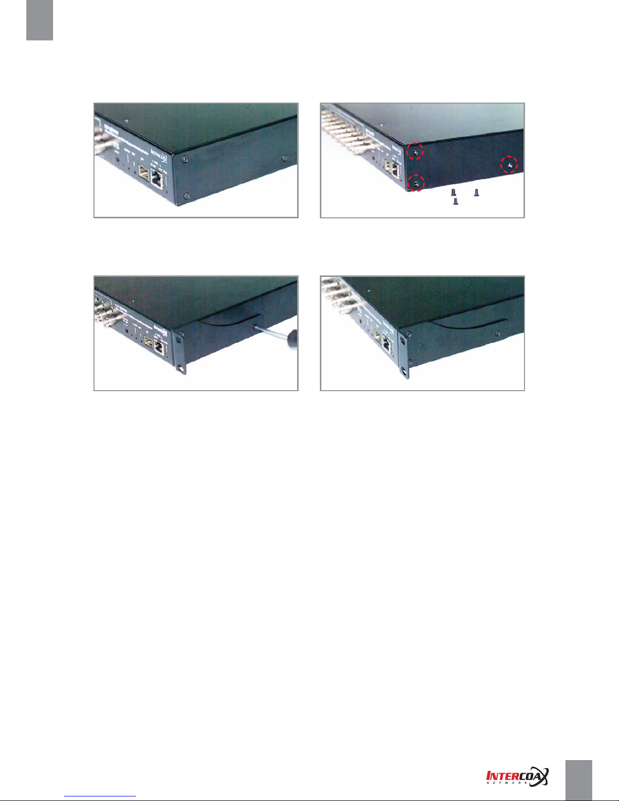
1. Remove the 3 of factory installed screws from both sides of managed switch and keep these screws
as they will be used to attach the new rack mount brackets. (See Picture 1 & 2)
2. Using these screws, attach the supplied rackmount bracket to the managed switch (Carefully check LEFT
and RIGHT side brackets, see pictures 3 & 4).
Rack Mount Instructions
1. Elevated Operating Ambient - If installed in a closed or multi-unit rack assembly, the operating ambient temperature
of the rack environment may be greater than room ambient.
Therefore, consideration should be given to installing the equipment in an environment compatible
with the maximum ambient temperature (Tma) specified by the manufacturer.
2. Reduced Air Flow - Installation of the equipment in a rack should be such that the amount of airflow required
for safe operation of the equipment is not compromised.
3. Mechanical Loading - Mounting of the equipment in the rack should be such that a hazardous condition is not
achieved due to uneven mechanical loading.
4. Circuit Overloading - Consideration should be given to the connection of the equipment to the supply circuit
and the effect that overloading of the circuits might have on overcurrent protection and supply wiring.
Picture 1 Picture 2
Picture 3 Picture 4
Page 11
Network Solution ProviderPage 11 of 41
High-Speed, Long distance Ethernet and PoE Extender
2-4-3. Joining instruction
Group A Group B Group C Group D
• All ECP/EUP products are pre-joined with the same network password (“HomePlugAV”) as the factory default mode
to support plug & play configuration between ECP/EUP Series.
• If the receiving switch and all of ECP/EUP-Transmitters are already Joined (Join LED on both devices),
It is unnecessary to join the devices again pressing JOIN button.
(In this case, please use the exclusive software, “ECP Manager” or “ECP Manager Lite” to join the new devices)
• ECP/EUP-28XXRM series have 2 or 4 network groups with every 4 channels (1-4, 5-8, 9-12, 13-16)
and It is possible to avoid network interference by setting the password of each group.
1. Basic connection
Prepare 4 short coaxial cables for convenience and connect each ECP/EUP-Transmitters
to Group A (B-Linx port 1 to 4) and apply the power to the receiving switch.
2. Unjoin (If required, when Join LED on both receiving switch and ECP-Transmitter is not ON)
Removing the password
A. Push the join button for 15 seconds on each unit of ECP/EUP-Transmitter in Group A.
B. ECP/EUP-Transmitter will reboot and it is ready to be joined.
C. BNC Join LED turns off.
3. Join (Recommend to join by ECP Manager software) :
Creating new password
A. After unjoining, press the Group A join button and hold for 2 seconds and release the button.
B. Press the join button on one of ECP/EUP-Transmitters and hold for 2 seconds and release the button.
PWR LED turns off and on, and then BNC Join LED turns on and will be flickering and it means
both devices are joined successfully.
C. Join other 3 units of ECP/EUP-Transmitters repeating above steps (A, B)
Page 12
Network Solution ProviderPage 12 of 41
High-Speed, Long distance Ethernet and PoE Extender
4. Repeat above ① ~ ③ steps for the other groups (B, C, D)
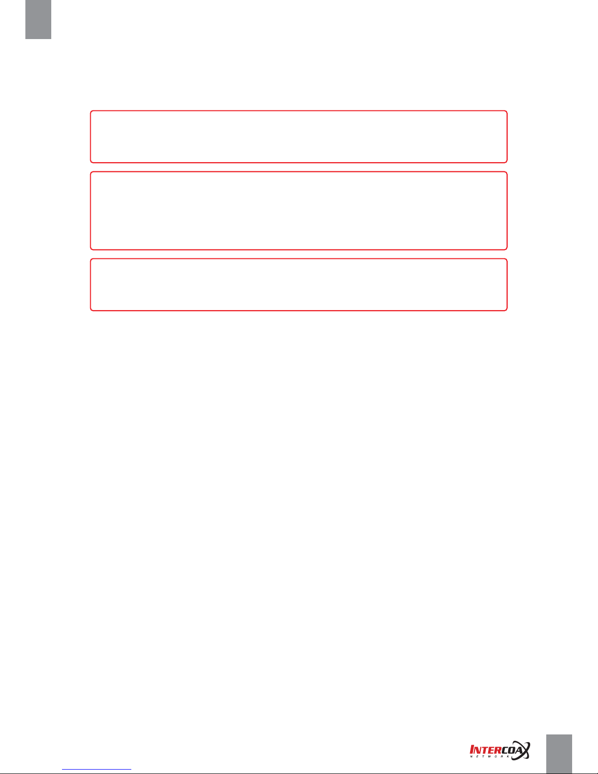
[Caution]
After joining work with Join button, a new and random password is automatically assigned
and it can not be restored to the factory default password.
[Note]
Joining can also be made with the exclusive management software, INTERCOAX ECP MANAGER
but before joining with software, the ECP-28XXRM series and ECP-Transmitters should already be
joined together with the same network group password. (For more details about software joining,
please refer to software setting page)
2-4-4. Label the configured network group
• After joining with the join button, it is highly recommended to put the label on the devices joined
in same network group and keep the documentation of Group ID and MAC address of the devices in each group.
• After joining with the software, it is highly recommended to put the label on the devices joined in same group
and password of the group and keep the documentation of Group ID and MAC address of the devices in each group.
• This documentation helps to identify each network group after deployment and when maintaining devices.
[Note]
Password on ECP/EUP-Transmitters can be also easily changed by Intercoax Manager software.
Please visit www.intercoax.com to download the software.
Page 13
Network Solution ProviderPage 13 of 41
High-Speed, Long distance Ethernet and PoE Extender
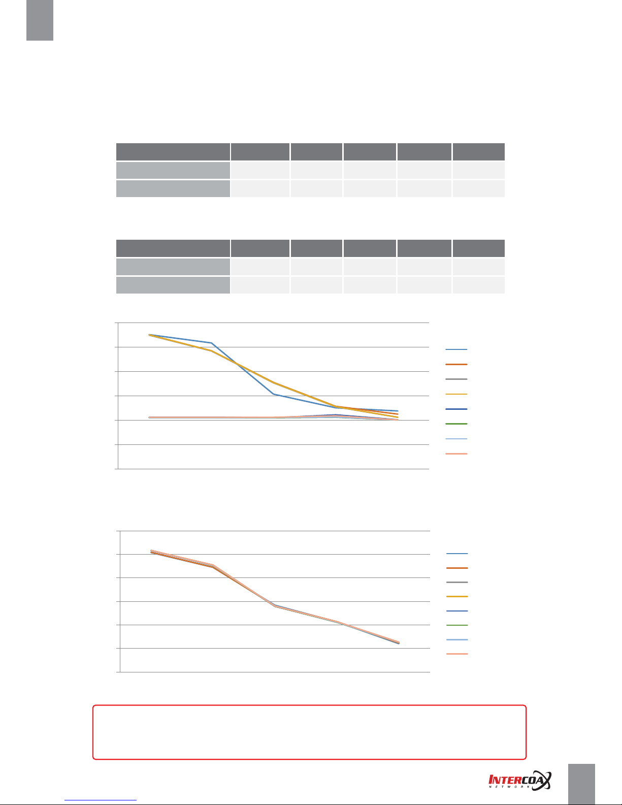
2-5. Transmission distance & Bandwidth by distance
2-5-1. Performance chart
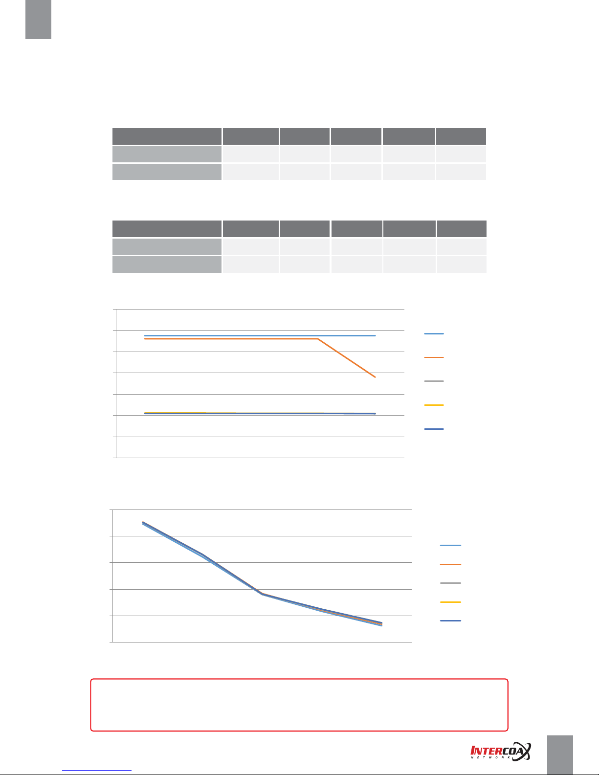
■ ECP-2808RM / ECP-2816RM (B-Linx Models)
• When using ECP-2XXX series as Transmitter (Based on One transmitter per port)
• When using ECP-9xxxx & 8xxxx series as Transmitter (Based on One transmitter per port)
RG6 Coaxial Cable
Trans. Rate (Mbps)
PoE Output (W)
50m
21.2
45.2
100m
21.2
33.1
200m
21.1
18.2
300m
21.1
12.5
500m
21
7.4
RG6 Coaxial Cable
Trans. Rate (Mbps)
PoE Output (W)
50m
57.5
45.3
100m
57.5
33.1
200m
57.5
18.4
300m
57.5
12.1
500m
50
6.9
* Above performance charts may vary depending on cable spec and installation environment.
Max. Transmission rate (Mbps) / meter
0
10
20
30
40
50
60
70
50m 100m 200m 300m 500m
ECP-2701
ECP-2601
ECP-9501
ECP-8401
ECP-8301
Max. PoE Output (Watt) / meter
0
10
20
30
40
50
50m 100m 200m 300m 500m
ECP-2701
ECP-2601
ECP-9501
ECP-8401
ECP-8301
Page 14
Network Solution ProviderPage 14 of 41
High-Speed, Long distance Ethernet and PoE Extender
2-5. Transmission distance & Bandwidth by distance
2-5-1. Performance chart
■ EUP-2808RM / EUP-2816RM (T-Linx Models)
• When using 2xxx series + BTE-02 (ECP Model only) as Transmitter as Transmitter
(Based on One transmitter per port)
• When using ECP/EUP-9xxxx & 8xxx series (ECP Models must have BTE-02) as Transmitter
(Based on One transmitter per port)
Cat.5e UTP Cable
Trans. Rate (Mbps)
PoE Output (W)
50m
21.2
51.7
100m
21.2
45.4
200m
21.1
28.1
300m
22.2
21.3
500m
20.2
12.6
Cat.5e UTP Cable
Trans. Rate (Mbps)
PoE Output (W)
50m
55.1
51.6
100m
51.7
45.5
200m
35.4
28.4
300m
25.7
21.4
500m
23.8
12.6
* Above performance charts may vary depending on cable spec and installation environment.
Max. Transmission rate (Mbps) / meter
0
10
20
30
40
50
60
50m 100m 200m 300m 500m
ECP-2701
ECP-2601
ECP-2801
EUP-2801
ECP-9501
ECP-8401
EUP-8401
ECP-8301
Max. PoE Output (Watt) / meter
0
10
20
30
40
50
60
50m 100m 200m 300m 500m
ECP-2701
ECP-2601
ECP-2801
EUP-2801
ECP-9501
ECP-8401
EUP-8401
ECP-8301
Page 15
ECP-2816RM
EoC
PoC
PoE Camera
ECP-2704T
Coax
PoE
Data
AC 100~240V
AC 100~240V
NVR
Network Switch
ECP-2701
Coax
Coax
Coax
ECP-2701
ECP-2701
ECP-2701
PoE Camera
PoE
Data
EUP-2816RM
EoC
PoC
ECP-2704T
Cat.5e or Better
ECP-2701
BTE-02
BTE-02
Cat.5e or Better
EUP-2601T
Cat.5e or Better
EUP-8401T
Cat.5e or Better
NVR
Network Switch
Network Solution ProviderPage 15 of 41
High-Speed, Long distance Ethernet and PoE Extender
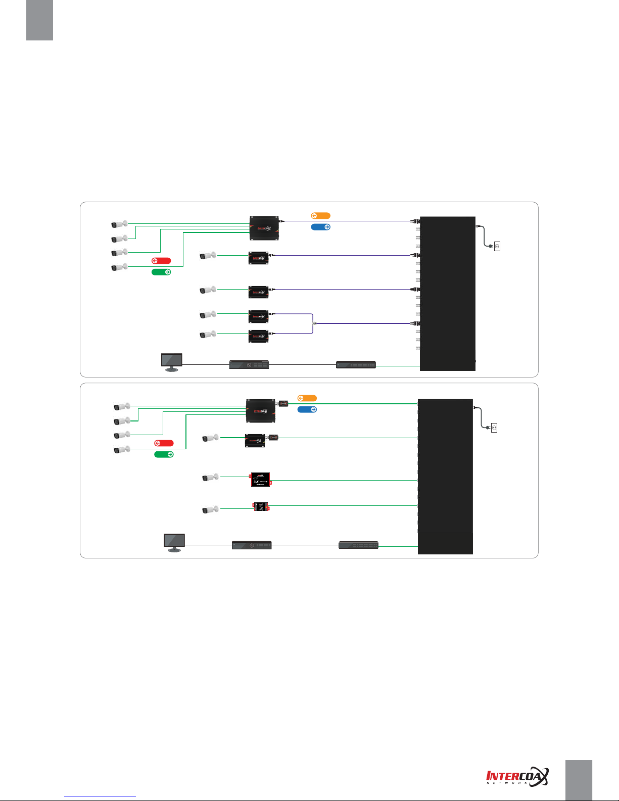
2-6. Typical Installation
•
The ECP/EUP-2808/2816RM Series deliver high bandwidth and power over coax/UTP cable.
All ECP/EUP single port units or ECP/EUP transmitter series can be used as remote transmitters,
typically located at the IP camera.
•
ECP/EUP-2xxxx series are recommended to be used as remote transmitters for the maximum performance.
Application Examples
48V~56V DC
Ethernet
PoE-PWR
Data-Link
Join-Link
Power ON
Join
PoE
OFF - ON
EUP-8401
Ethernet over Coax Transceiver
Page 16
Model ECP-2808RM EUP-2808RM ECP-2816RM EUP-2816RM
IGMP (V1/V2 /V3) Sn ooping, IGMP Query & Report Generator
Coax
Up-Link
1 x RJ45 - 10/1 00/1, 000 Base-T with Auto MDIX, 1 x SFP - 1,000 Base-T
AC100 V~240V (50Hz /60Hz ), 320W
Max DC 56V , 1.07 A (60W per port for PoE support)
Auto Detecon & Protecon
UP to 560Mbps Full Duples UP to 1Gbps Full Duples
B-Linx / T-Linx Transmission Rate
(Ethernet over Coax/UTP)
Inte rface
441.5(L) x 349(W) x 44(H)mm
CE (including Railways Standard EN 50121 -4), FCC , KC, UL
IEC6100 0-4-5 4kV (1.2 / 50us), 2kA(8 /20us)
Compliance
Mechanical
Power
0C ~ +60C
-30C ~ +80C
10% ~ 80%
Environment
IEEE1901-HPAV
OFDM
up to 2 remote converters per port recommended (Max up to 4 per port)
Available
B-Linx / T-Linx Communicaon Standard
B-Linx / T-Linx Communicaon Modulaon
B-Linx / T-Linx Communicaon
Mulple Nodes (Daisy Chain)
ECP Manager Connecvity
IGMP
Blue
Buzzer / Mute
128-bit AES
Green (10/ 100-Li nk) / Yellow (1,000 -Link)
Green
Green (1,0 00-Link)
Red
Green
Buzzer
LED Indicaon
Power
RJ45 Up-Link
SFP Up-Link
Channel
Join
Alarm
Event
Encrypon
Smart B-Linx / T-Linx Device Detecon
4,650g
4,600g 5,090g 5,030g
Up to 1,200m (RG6 / 7W)
Up to 3,000m (Cat.5e)
Coax
UTP
Up to 2,300m (RG6)
Up to 1,200m (Cat.5e)
Up to 1,500m (Cat.5e / 7W)
Data Transmission
Distance
Power Transmission
Distance
Coax
UTP
DC output per Port
AC Input
Port Short Protecon
Surge Protecon
Cerficaon
Weight
Dimension
Storage Temp
Operang Temp
Relave Humidity
UTP
8 * 75Ω BNC (Female) -
Ethernet over Coax (B-Linx)
8 * 100Ω RJ45 (Female) -
Ethernet over Twisted Pairs (T-LinX)
16 * 75Ω BNC (Female) -
Ethernet over Coax (B-Linx)
16 * 100Ω RJ45 (Female) -
Ethernet over Twisted Pairs (T-LinX)
Detecon On / Off
441.5(L) x 340(W) x 44(H)mm
441.5(L) x 349(W) x 44(H)mm 441.5(L) x 340(W) x 44(H)mm
Network Solution ProviderPage 16 of 41
High-Speed, Long distance Ethernet and PoE Extender
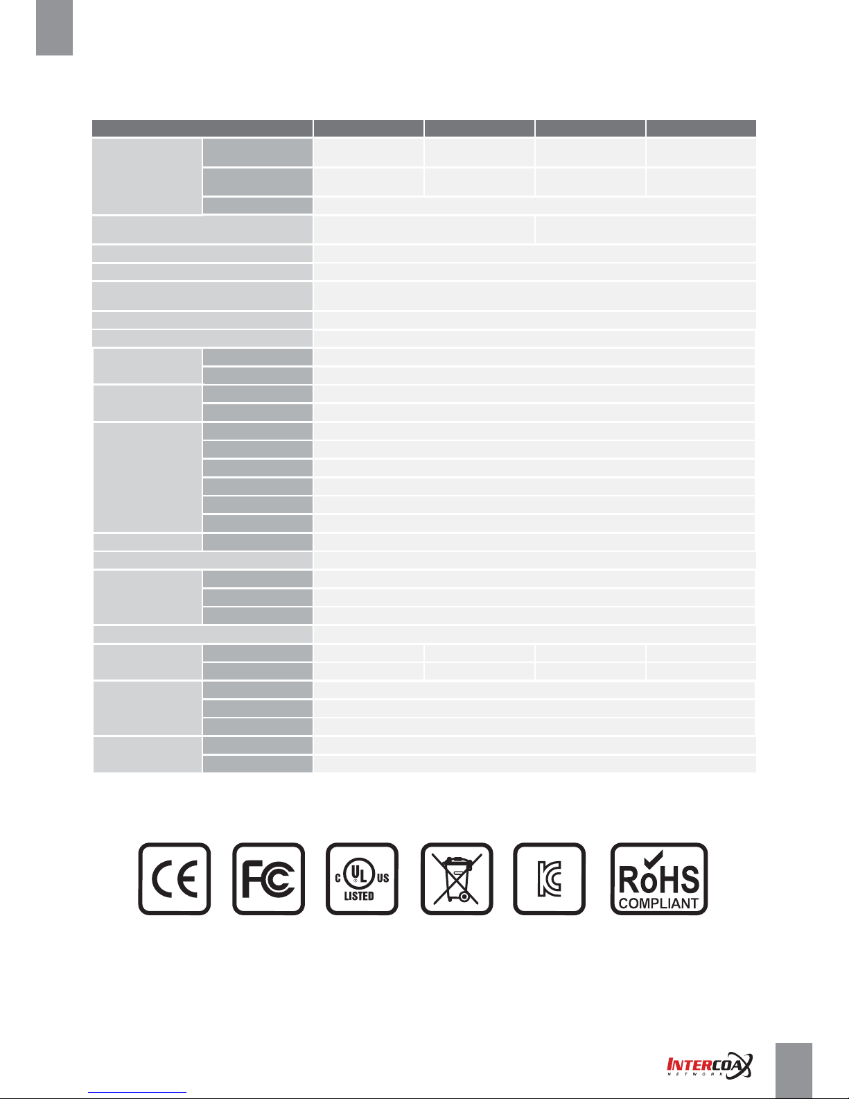
3. Product Specifications
3-1. Technical Specifications
3-2. Regulatory Certifications
Page 17

Network Solution ProviderPage 17 of 41
High-Speed, Long distance Ethernet and PoE Extender
4. Management Software Configuration
4-1. Overview
ECP MANAGER LITE & ECP MANAGER
• The ECP MANAGER LITE is the browser based GUI. Users can access to management of all ECP-2808/16 series
and its connected IEEE1901-HPAV standard transmitters.
• The ECP MANAGER software allows managing multiple of INTERCOAX Managed Receivers remotely from
the central management office. With the ECP MANAGER software, users can access to all connected
IEEE1901-HPAV standard transmitters.
• Various additional features are available with the ECP Manager and ECP Manager Lite as below;
Remote monitoring for ECP devices & End or remote (usually Tx models) device connection
Remote transceiver Joining (Network Grouping)
IP addressing for managed EoC Switch
System reboot
Power reset by each port
Real time Monitoring for power consumption by each port
Real time Monitoring for total power consumption
Port locking for extra secured network connectivity
Multicast setting with IGMP Query Generation
Scheduled event reporting and alert reporting to designative users
SNMP Setting
Firmware upgrade for managed EoC Switch
VLAN Setting
Configuration backup & Restore
4-2. System Requirements
• Recommended Operating System for ECP Manager : Window 7 or Higher version
• Recommended Version of Internet Explorer for ECP Manager Lite : Window 8 or Higher version
• Internet connectivity : During initial installation for ECP manager, Internet connectivity is required.
Page 18
Network Solution ProviderPage 18 of 41
High-Speed, Long distance Ethernet and PoE Extender
4-3. Getting started
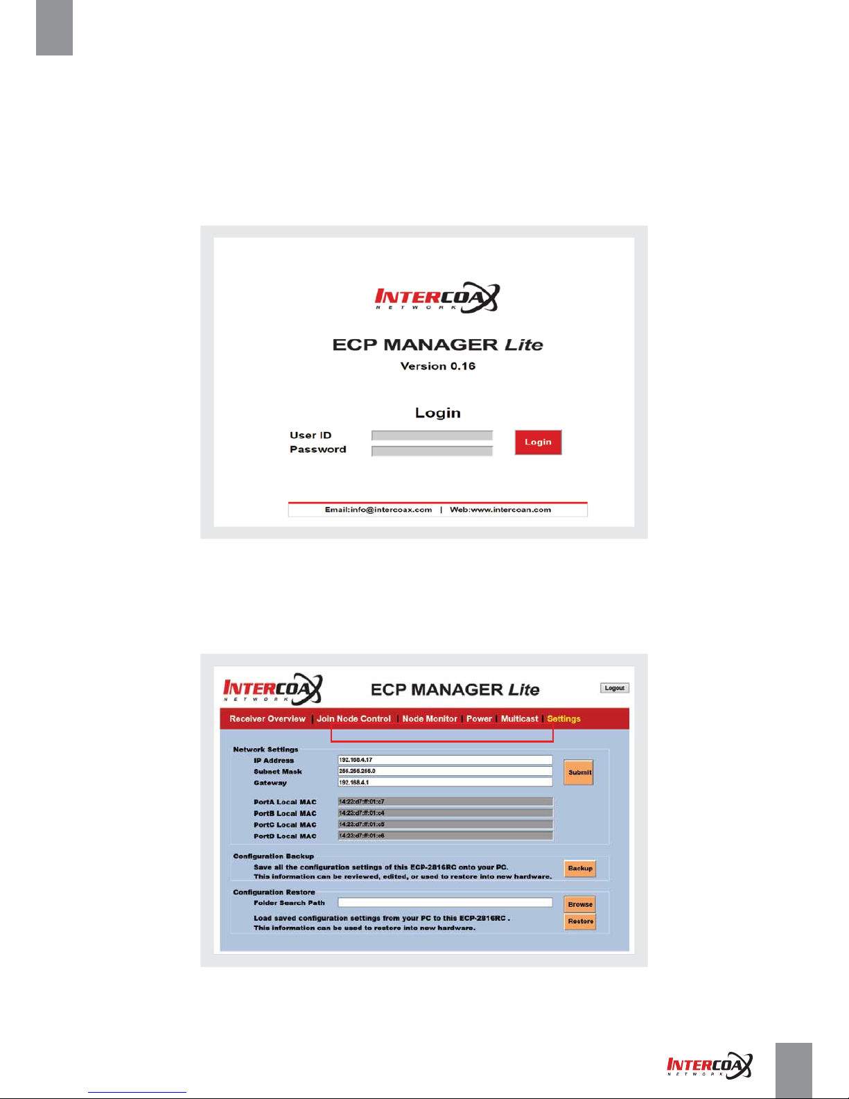
4-3-1. ECP MANAGER LITE
1. Under network setting, set your PC’s IP address to 192.168.4.xxx and subnet mask to 255.255.255.0.
2. Open the web browser and enter http://192.168.4.17, the factory default IP address of the ECP Managed Switch.
3. Login window will be opened on web browser.
4. Enter the default User ID, "admin"
5. Enter the default Password, "admin"
6. Open the Setting page and change IP address as desired address.
7. Change Login ID and Password on Admin page of the Intercoax ECP Manager.
[Note] Please refer to Admin page for changing Admin ID and password (Page 36)
Page 19
Network Solution ProviderPage 19 of 41
High-Speed, Long distance Ethernet and PoE Extender
4-3. Getting started
4-3-2. ECP MANAGER
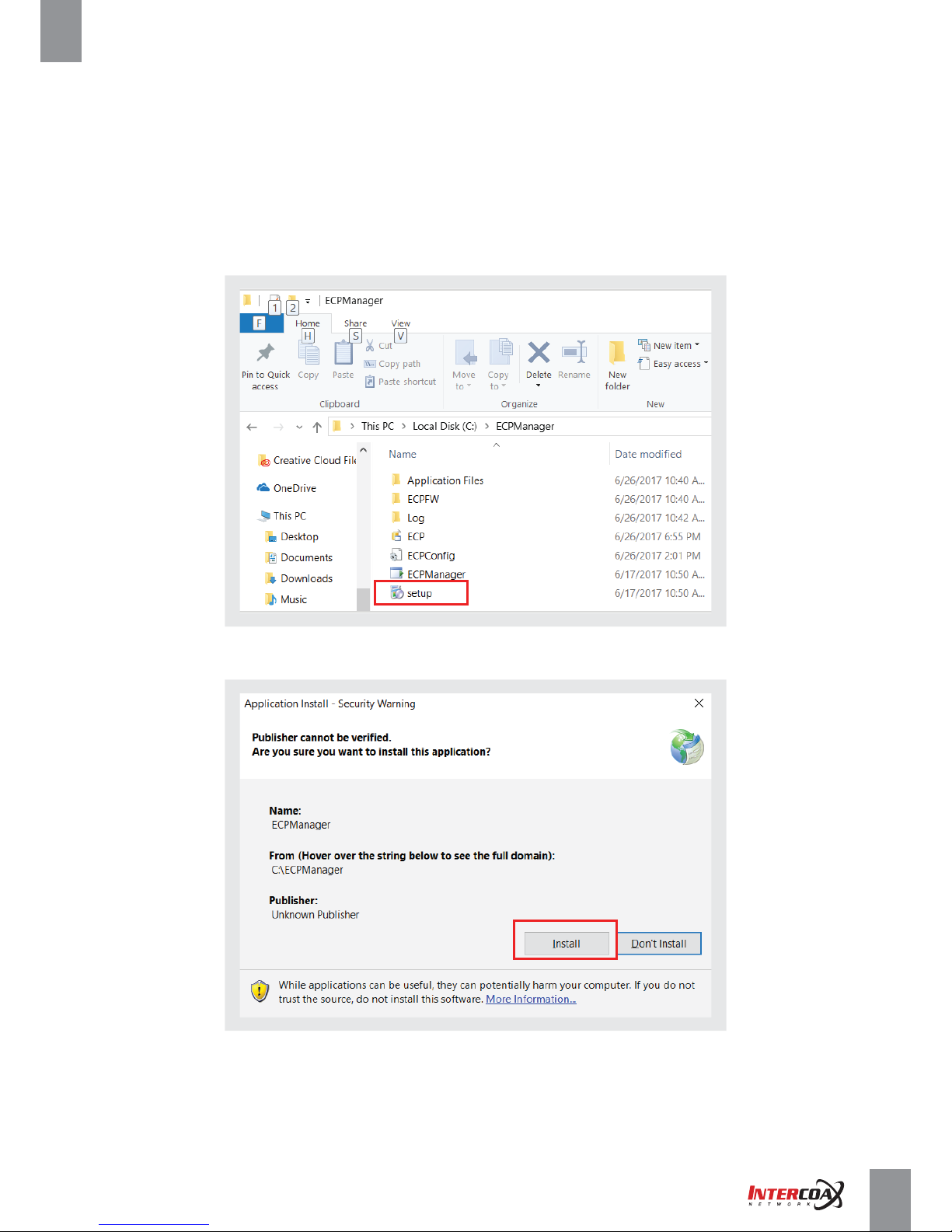
1. Unzip the file, ECPManager.zip
2. Move the unzipped folder, ECPManager to Local Disk (C:) => Location: C:\ECPManager
3. Click the setup.exe file
[Note] During initial Installation for ECP Manager. Internet connectivity is required.
4. Click the Install button on Application Install – Security Warning window.
5. Installation procedure will be done.
6. Start ECP Manager software.
7. Default Login ID: admin
Default Login Password: admin
Page 20
Network Solution ProviderPage 20 of 41
High-Speed, Long distance Ethernet and PoE Extender
4-3. Getting started
4-3-2. ECP MANAGER
8. Change the Login ID and Password as desired on the Admin window.
[Note] Please refer to admin window page for changing ID and Password (Page 36)
9. Create a group on Group Configuration tab of ECP Config Window.
[Note] Please refer to Group configuration window for creating Group (Page 33)
10. Add new ECP managed switch on ECP Configuration tab of ECP Config Window.
[Note]
- Please refer to ECP configuration window for adding New ECP managed switch (Page 34)
- When adding ECP managed switch, please Enter the default IP, 192.168.4.17.
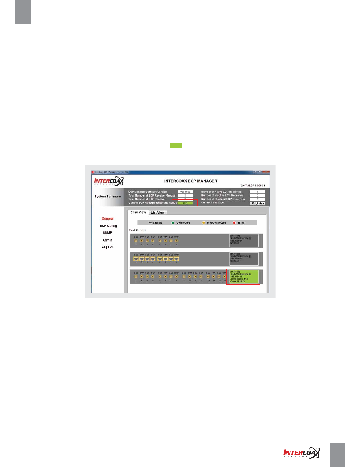
11. IF new ECP managed switch is added correctly, O.K message will be shown on the Current ECP Manager
Reporting Status of the System summary and the background color of the device ID will be changed to green
12. Change the IP address as desired on the Setting menu of the General Window.
[Note] Please refer to Setting menu on General window (Page 31)
Page 21
Network Solution ProviderPage 21 of 41
High-Speed, Long distance Ethernet and PoE Extender
4-4. Configuration Windows
4-4-1. System Summary
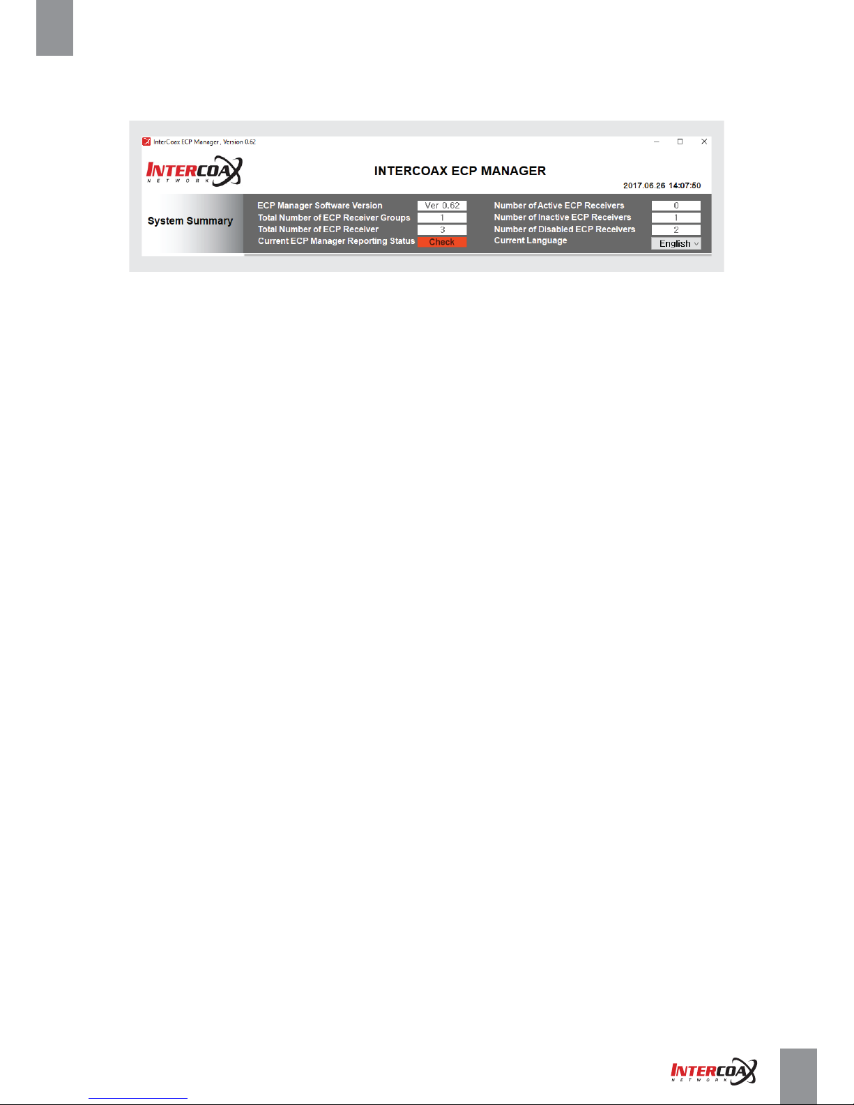
• System summary shows the system configuration of the connected ECP managed switches.
• System summary information will be shown on all windows.
- ECP Manager Software Version shows the version of the current software.
- Total number of ECP Receiver Groups shows the total number of the registered group.
- Total number of ECP Receiver shows the total number of the registered ECP managed switches.
- Current ECP Manager Reporting Status shows connection & reporting status of the devices
► Check: All or some devices is not reporting status to the ECP Manager or software or network c
onnection failure.
► O.K: All devices connected to the software are reporting status correctly.
- Number of active ECP Receivers: This shows a number of the activated devices.
- Number if inactive ECP Receivers: This shows a number of the inactivated devices.
- Number if Disabled ECP Receivers: this shows a number of the disabled devices.
- Current Language: Select the desired language of the software (English is set as default value)
Page 22
Network Solution ProviderPage 22 of 41
High-Speed, Long distance Ethernet and PoE Extender
4-4-2. General Window
4-4-2-1 Easy View
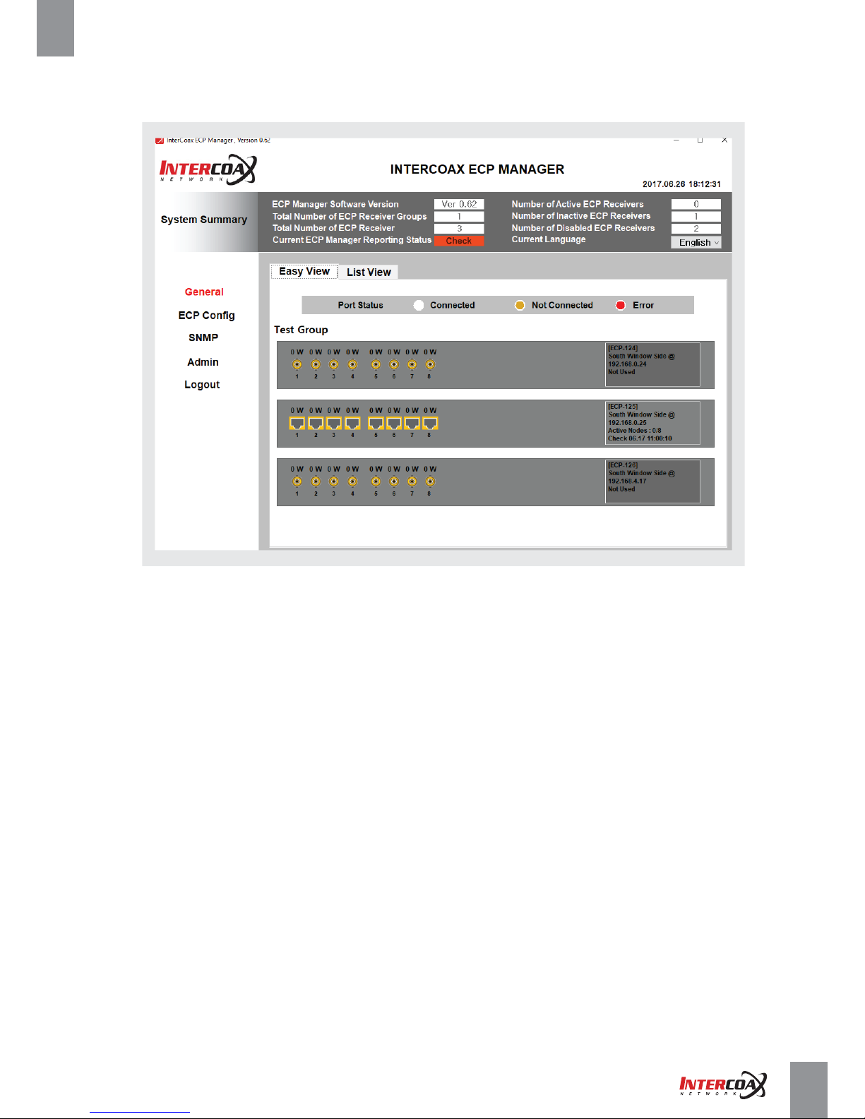
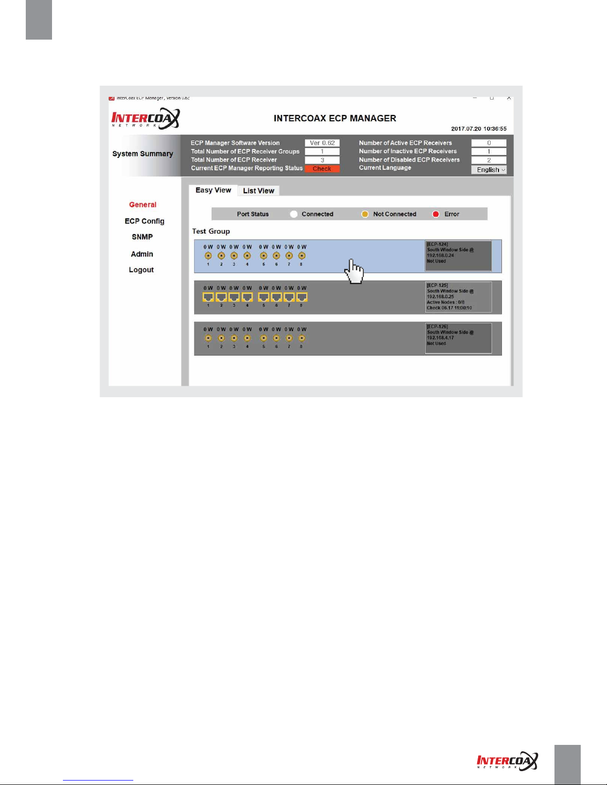
• Installed ECP Managed Receivers are shown on General – Easy View.
• ECP Manager is programmed to check the connectivity of each ECP Managed Receivers automatically.
If an ECP Managed Receiver is connected to ECP Manager, then the box on the right will stay green.
• B-Linx and T-Linx ports will be changed to RED color when there is an error on each port. For example, when
the cable is shorted or damaged, the port color will change to RED and it will stop transmitting power over
B-Linx and T-Linx ports.
Page 23
Network Solution ProviderPage 23 of 41
High-Speed, Long distance Ethernet and PoE Extender
• By Clicking on the GUI of the corresponding device, users can enter the menu of each device.
• Each device GUI shows;
- Port connection status (All connected B-Linx and T-Linx port will be showed with Green color)
► Green: normal ► Yellow: No connected ►Red: error
- Power consumption by each port
- Registered device ID & location
- ID Address of the device
- Active node: Number of connected ECP Transmitters
- Check time: The time that the software lastly checked the ECP managed switch.
Clicking
Page 24
Network Solution ProviderPage 24 of 41
High-Speed, Long distance Ethernet and PoE Extender
4-4-2. General Window
4-4-2-2 List View
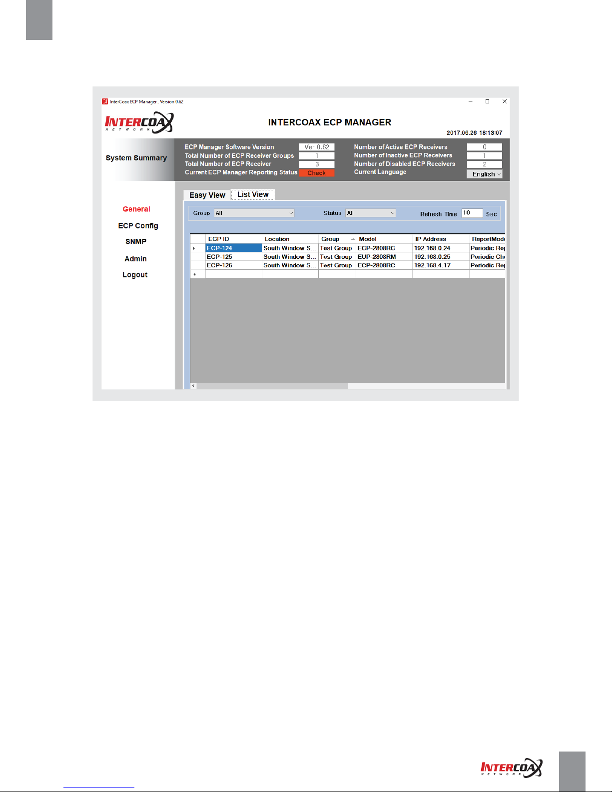
• Installed ECP Managed Receivers are also shown on General – List View.
• When there are many ECP Managed Receivers are installed, it is convenient
to control all installed ECP Managed Receivers on List View.
• Each device list and table shows;
- ECP ID: The registered device ID
- Location: The location of the registered device
- Group: The group name of the registered device
- Model: The model number of the device
- IP Address: The IP Address of the device
- ReportMode: Selected reporting Mode
- ReportPeriod: Time period for device status reporting
- Local Node: Mac address of ECP Managed Switch
- Remote Node: Mac address of ECP Transmitters connected to the ECP Managed switch
- Check time: The time that the software lastly checked the ECP managed switch.
Page 25
Network Solution ProviderPage 25 of 41
High-Speed, Long distance Ethernet and PoE Extender
4-4-2. General Window
4-4-2-3 Receiver Overview
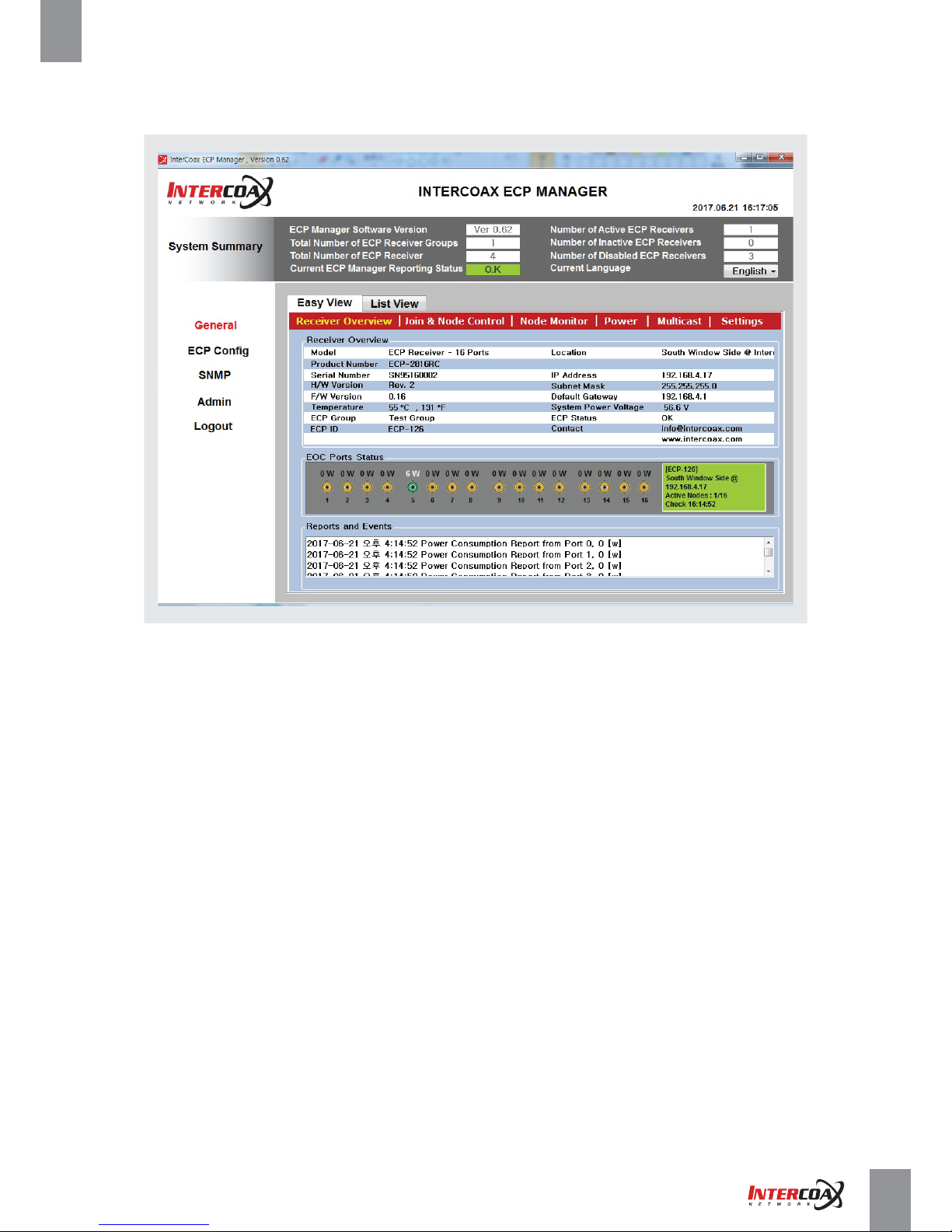
• By Clicking on the GUI of the corresponding device GUI on Easy view, users can enter the configuration menu
of each device.
• Receiver Overview shows the brief information of the selected device such as;
- Model: Product type
- Product Number: Product number
- Serial Number: Serial number of the selected device
- H/W version: Hardware version
- F/W Version: Firmware version of the hardware
- Temperature: Current temperature of the device
- ECP Group: Assigned group name
- ECP ID: Assigned ID of the device
- Location: Location of the device deployed
- IP Address: IP address of the device
- Subnet Mask: Subnet mask of the device
- Default Gateway: Gateway of the device
- System Power voltage: System power status
- ECP status: Connection Status of the device
- Contact: Contact information
• EOC Ports Status show the port number, the connection status of each port and power consumption of each port.
- When ECP/EUP Transmitters are connected to the ports, the port color will be changed from Yellow to Green.
- When there is over current by damage or short on cable, the port will immediately shuts off the power
and the port color will be changed to Red.
• Reports and Events shows the connected time of the ECP/EUP Transmitter and the power consumption
of the connected devices by the port.
Page 26
Network Solution ProviderPage 26 of 41
High-Speed, Long distance Ethernet and PoE Extender
4-4-2. General Window
4-4-2-4 Join & Node Control
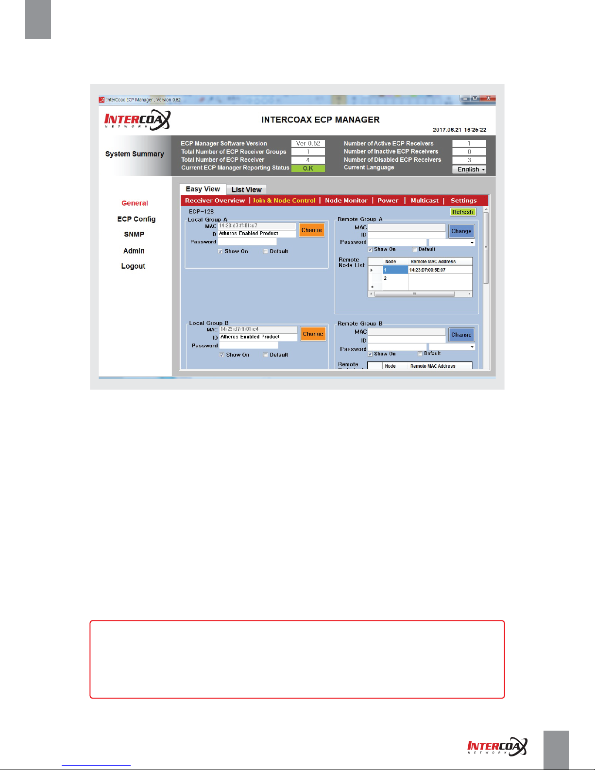
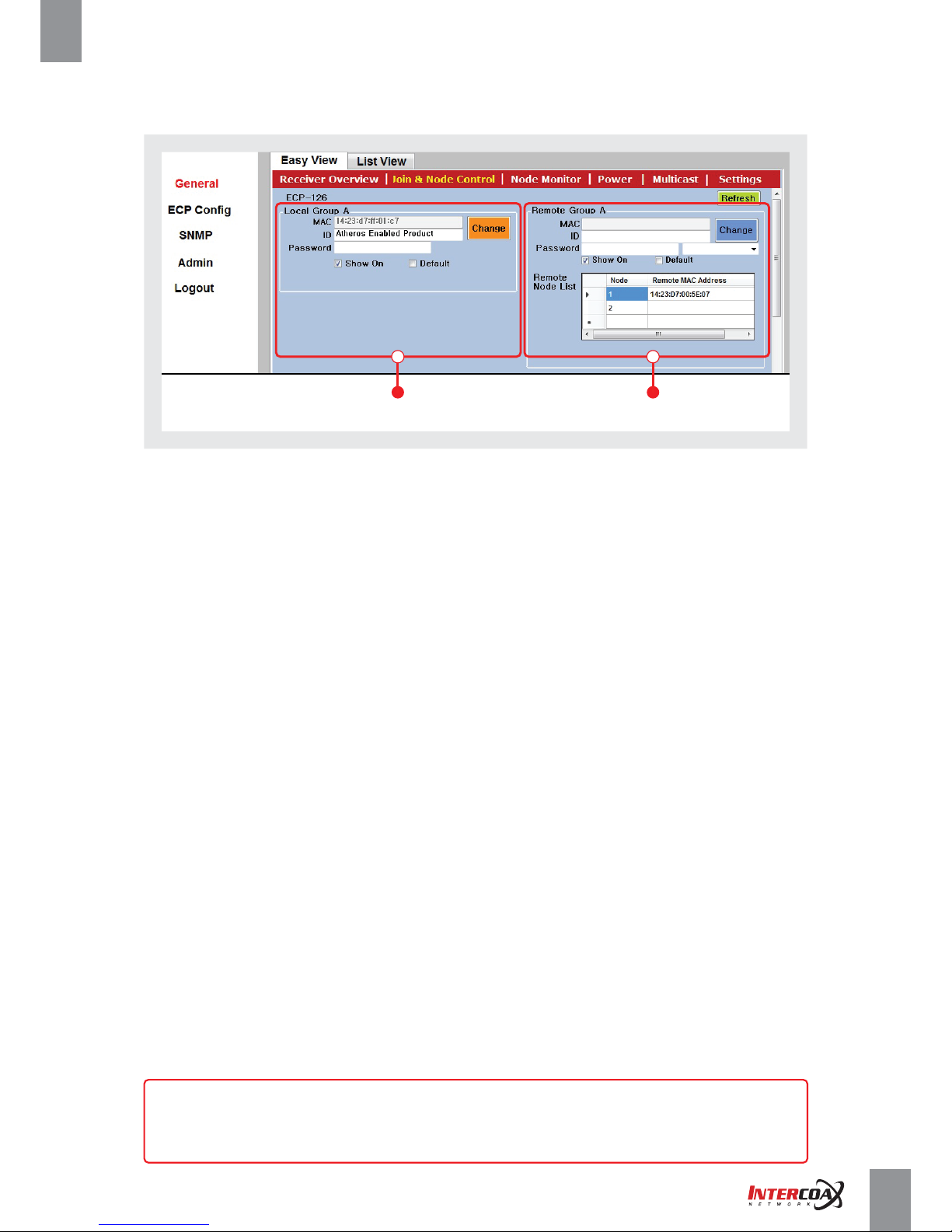
• On this menu, users can make network groups by joining the connected ECP/EUP Transmitters
with ECP/EUP managed switch.
• ECP/EUP managed switch series have 2 or 4 network groups with every 4 channels (1-4, 5-8, 9-12, 13-16)
and it is possible to avoid network interference by setting the different password of each group.
• Each Local Join Group shows information about receiver’s IEEE1901-HPAV chipset. For example,
8 port receiver has two IEEE-1901-HPAV chipsets. Port 1~4 dedicates to join group A and Port 5~8 dedicates
to Join group B. All ECP/EUP managed switch series have the default password, “HomPlugAV” from the factory.
• Remote Join Group shows information about connected remote transmitters’ IEEE1901-HPAV chipsets.
All remote transmitters must have “HomePlugAV” password in order to be connected to Local Join Groups.
All ECP/EUP transmitters have the password, “HomPlugAV” from the factory.
• It is recommended to set the different password for secured connection between different network groups.
[Note]
- Please REMEMBER to change password on remote first, then local after.
- If not, the Local Group cannot recognize the devices of the Remote Group and in
this case, users should know the exact password of the remote group for joining.
Page 27
Network Solution ProviderPage 27 of 41
High-Speed, Long distance Ethernet and PoE Extender
4-4-2-4 Join & Node Control
• Local Group A, B or A, B, C, D
- This section shows the information of each Local Group (IEEE1901-HPAV chipset), ECP managed switch side.
- MAC: Mac address of the each Group’s chipset (MAC address is read automatically from the device)
- ID: Each Group’s ID that registered already as factory default. Enter new ID as desired.
- Password: Enter new password for creating the network group with the Remote Group (Joining)
- Show On: If checked, the password will be shown.
- Default: If checked, the factory default password, “HomePlugAV” will be entered.
• Remote Group A, B or A, B, C, D
- This section shows the information of each Remote Group (IEEE1901-HPAV chipset), ECP/EUP Transmitters side.
- To select the each device, please click the corresponding Remote MAC address part on the listing of the devices
- MAC: Mac address of the each Group’s chipset (MAC address is read automatically from the device)
- ID: Each Group’s ID that registered already as factory default. Enter new ID as desired.
- Password: Enter new password for creating the network group with the Local Group (Joining)
- Show On: If checked, the password will be shown.
- Default: If checked, the factory default password, “HomePlugAV” will be entered.
• Refresh Button : Refresh the current joining status.
Local Group Remote Group
[Note]
Changing password (Joining) of any of each local or remote device may take
up to a few minutes in order to show.
Page 28
Network Solution ProviderPage 28 of 41
High-Speed, Long distance Ethernet and PoE Extender
4-4-2-5 Node Monitor
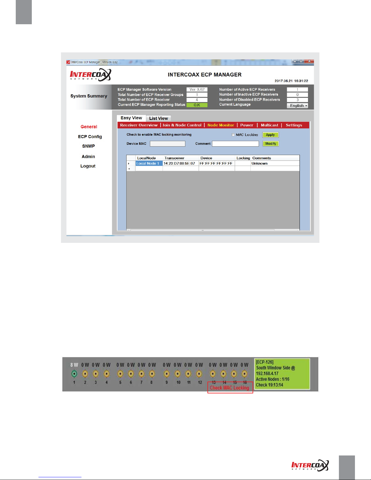
• This menu shows the MAC address of the ECP/EUPTransmitters and the end devices connected to each Local Node.
• Comments on each IP device is very useful to identify the devices.
• To select the device, please click the MAC address part of the corresponding device on device listing.
• MAC Locking
- Users can check “MAC Locking” checkbox to lock the MAC address of all connected devices.
- MAC locking status will be displayed on the “Locking” part of the device listing.
- IF MAC address of the connected device changed after Mac Locking box checked,
“Check MAC Locking” message will be displayed on the device GUI of the Easy View window.
• Device MAC: the Device MAC address will be shown automatically when clicking the device.
• Apply button: Apply MAC Locking feature.
• Comment: Enter descriptions of the device such as location, device number, IP address, etc.
• Modify Button: Apply the comment modification.
Page 29
Network Solution ProviderPage 29 of 41
High-Speed, Long distance Ethernet and PoE Extender
4-4-2-6 Power
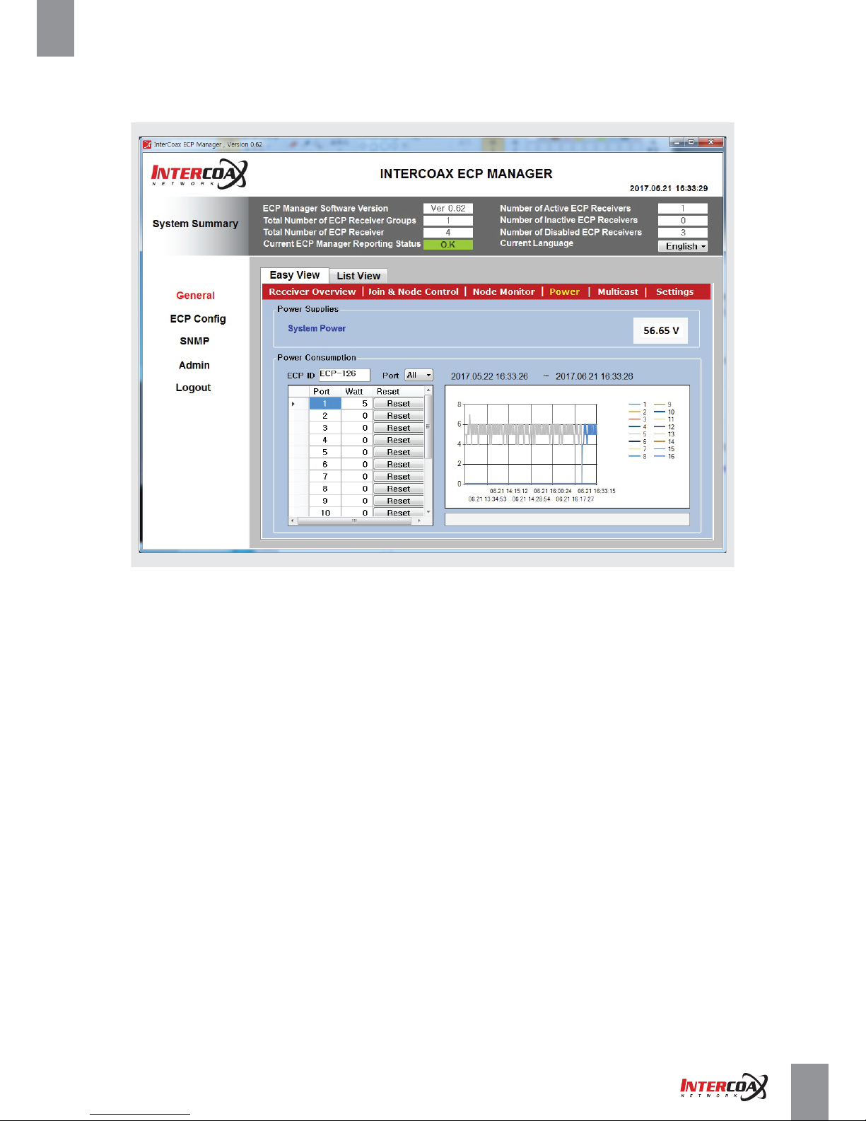
• Power page shows all power information of the ECP managed switch and power usage
on every port with the line graph.
• In this page, users can check the system power voltage and the power consumption of the ECP/EUP Transmitters
including the end-devices by each port.
• Port reset will shut down the power and retransmit the power on each port and it is convenient
to reboot the transmitter and its connected end-devices.
• Power Supplies
- System Power: current system power voltage will be displayed.
• Power consumption
- ECP ID: ID of the selected ECP Managed Switch
- Port: Port number
- Watt: Current power consumption by each port
- Reset Button: Pressing the button, power over B-Linx or T-Linx port feature will be cut down for 3 seconds
and retransmitted on each port.
Page 30
Network Solution ProviderPage 30 of 41
High-Speed, Long distance Ethernet and PoE Extender
4-4-2-7 Multicast
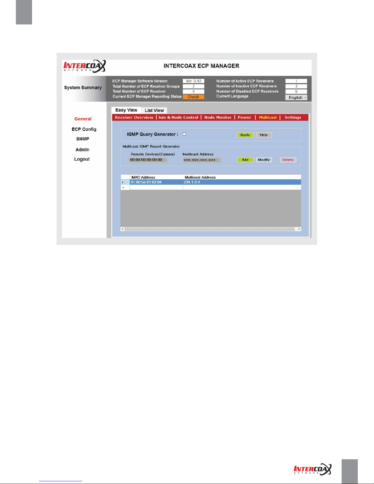
• Multicast menu shows all added multicast addresses.
• On this page, users can add the new multicast address as desired and turn on IGMP query generator for IGMP Snooping
for all added multicast streams.
• For multicast streaming, IGMP Query Generator must be checked on to generate IGMP Query
and multicast IP address should be added on the listing.
• IGMP Query Generator
- Checked: IGMP Query Generator is used.
- Unchecked: IGMP Query Generator is not used.
- Apply Button: Apply IGMP Query Generating
• Multicast IGMP Report Generator
- Remote devices: MAC address of the end device (e.g. camera) will be displayed.
- Multicast address: Multicast address of the end device will be displayed.
- To select already added multicast address, please click the multicast address on the listing.
- Add Button: Add new Multicast address.
- Modify Button: Modify the multicast address as desired.
- Delete Button: Delete the selected device with the corresponding multicast address
Page 31
Network Solution ProviderPage 31 of 41
High-Speed, Long distance Ethernet and PoE Extender
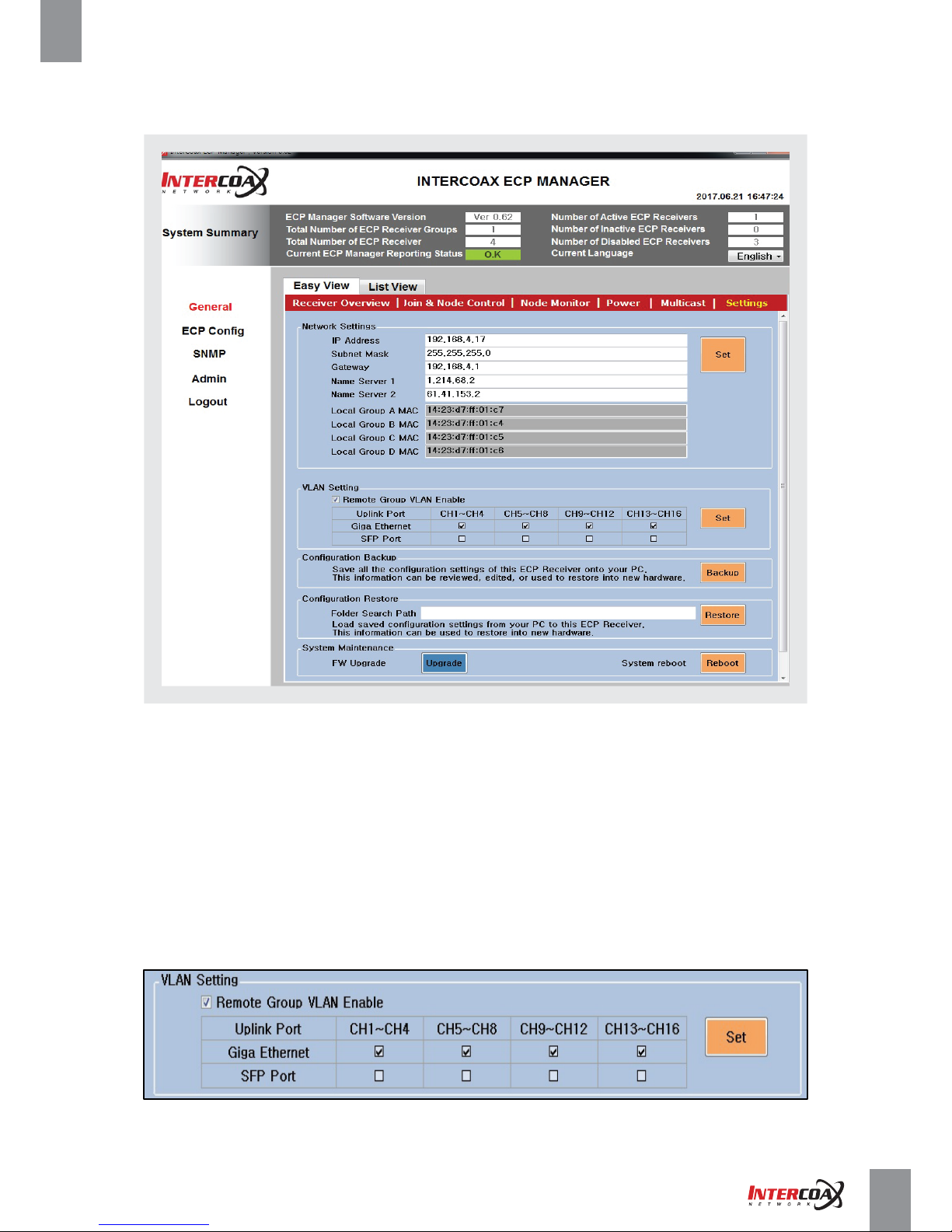
4-4-2-8 Settings
• On the Settings menu, users can set the network addressing of the device, the VLAN and backup and restore
the device configuration, update the firmware and reboot the system.
• Network settings
- IP Address, Subnet Mask, Gateway, Name Server 1, Name Server 2 : Enter the desired address.
- Local Group A / B / C / D MAC : Pre-registered Local Node MAC addresses are displayed automatically.
• VLAN Setting
- On VLAN Setting menu, users can specify the uplink path for each group.
Page 32
Network Solution ProviderPage 32 of 41
High-Speed, Long distance Ethernet and PoE Extender
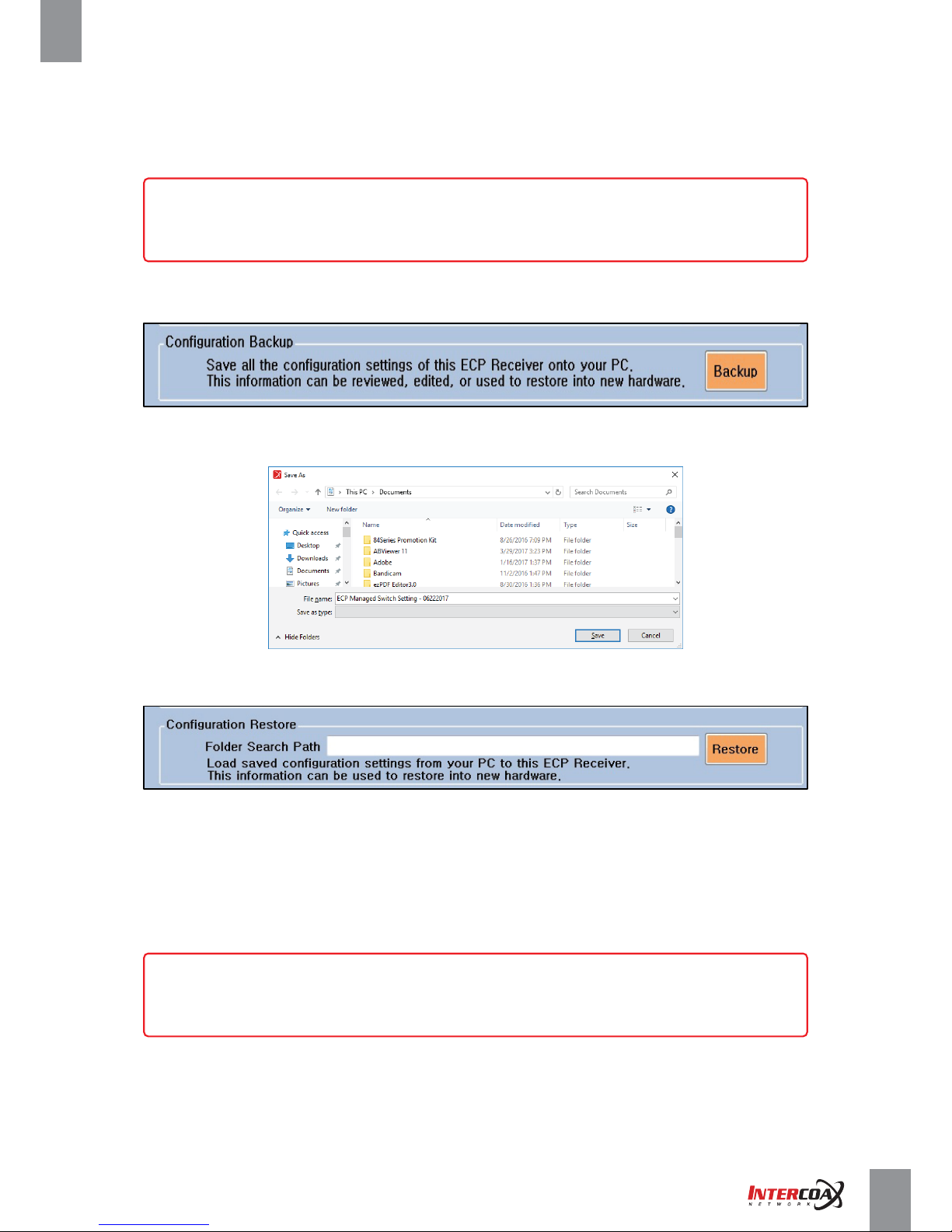
4-4-2-8 Settings
•
Configuration Backup: Backup all current setting of the selected ECP/EUP managed Switch.
- Press Backup button and Save the setting with a desired file name.
• Configuration Restore: Restore the saved setting of the selected ECP/EUP Managed Switch.
- Press Restore button and Open the saved setting file on specified path.
• System Maintenance
- Firmware update
Press the Upgrade button after moving the downloaded firmware file to the path, C:\ECPManager
- System Reboot
Press the Reboot button when system reboot is required.
The Management system will be rebooted but system reboot does not affect the transmission
of network signals between devices.
- Check Remote Group VLAN Enable Box to activate the VLAN feature and check the each
group box to select uplink path to Giga Ethernet or SFP port.
[Note]
ECP/EUP Managed Switch series have 2 or 4 network groups with every channels
(1-4, 5-8, 9-12, 13-16) and VLAN Settings are conducted on each group.
[Note]
Please inquire about new version of the firmware to the manufacturer.
Page 33
Network Solution ProviderPage 33 of 41
High-Speed, Long distance Ethernet and PoE Extender
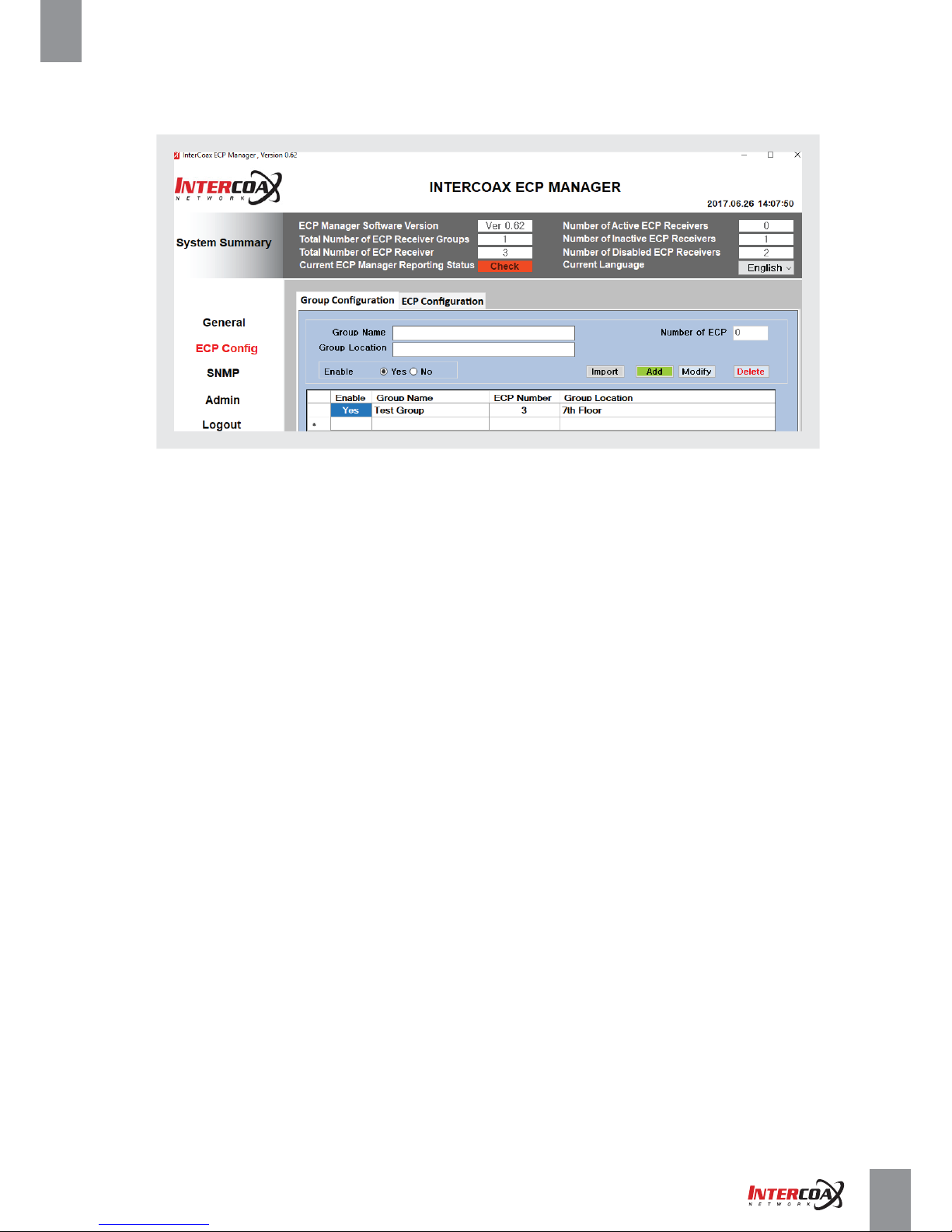
4-4-3 ECP Config Window
4-4-3-1 Group Configuration
• On the Group Configuration menu, users can create a new group of the ECP managed switches.
• The information of the selected device will be shown by clicking the device on the table.
- Group Name: Enter the desired group name.
- Group Location: Enter the Location where the device is deployed.
- Number of ECP: This shows a number of ECP managed Switch on the Group.
- Enable
► Yes – The selected group will be activated on the General Menu.
► No – The selected group will not be activated on the General Menu.
- Add Button: Add the Group.
- Modify button: Modify the information.
- Delete button: Delete the selected group
Page 34
Network Solution ProviderPage 34 of 41
High-Speed, Long distance Ethernet and PoE Extender
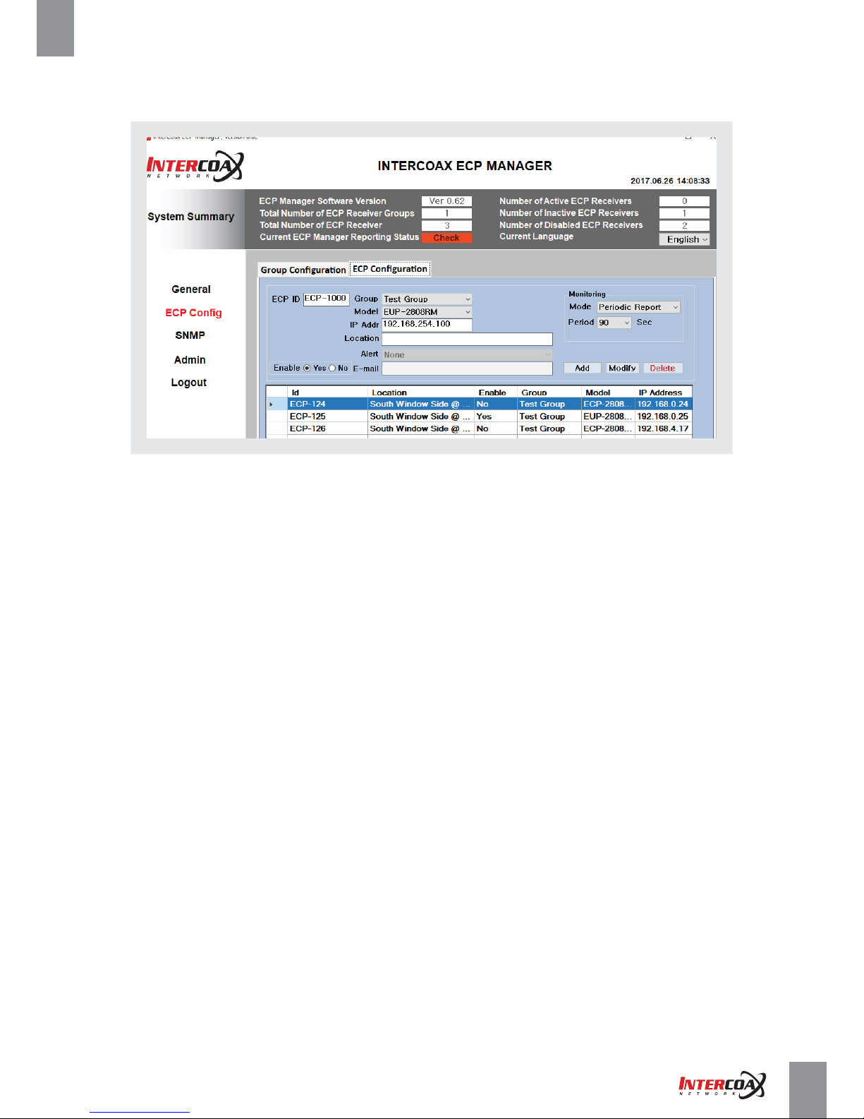
4-4-3 ECP Config Window
4-4-3-2 ECP Configuration
• On the ECP Configuration menu, users can add new ECP managed switch.
- ECP ID: Enter a desired ID of the device.
- Enable:
► Yes - The device monitoring will be activated on the General Menu.
► No - The device monitoring will not be activated on the General Menu.
- Group: Select the group already created from Group Configuration.
- Model: Select the device type by product type (Coax/UTP) and Channel (8Ch / 16Ch).
- IP Addr: Enter the IP address of the device.
(Note: the factory default IP address of the device is 192.168.4.17)
- Location: Enter the location where the device is deployed.
- Alert: Send an email about device status to registered e-mail address.
- Monitoring:
► Mode: Select monitoring option.
▪ Periodic Report: The device reports the current status every selected period (Recommended)
▪ Periodic Check: ECP Manager checks the current status of the connected devices continuously.
▪ None: Not monitoring automatically.
► Period: Designate the time period to check the device status.
- Add Button: Add the device.
- Modify Button: Modify the information of the selected device.
- Delete Button: Delete the selected device.
Page 35
Network Solution ProviderPage 35 of 41
High-Speed, Long distance Ethernet and PoE Extender
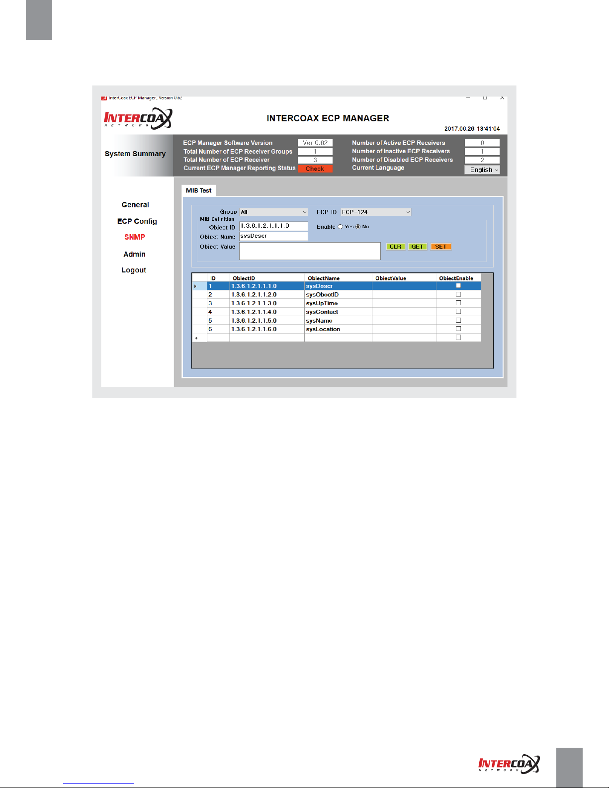
4-4-4 SNMP Window
• Using the SNMP protocol, the system or network administrator can monitor the device.
• As the default setting, 6 objectIDs are available, for specified function, please contact to the manufacturer.
MIB (Management Information Base) Test
- Group: Select an assigned group.
- ECP ID: Select an registered device ID in the group.
- Object ID: Enter the name used to identify the object.
- Enable: Check yes tab if you need to activate the assigned object ID.
- Object Name: Enter the object name.
- Object Value: Enter the object description.
- CLR Button: Clear the object value
- GET Button: Retrieve the information from the device.
- SET Button: Save the information.
Page 36
Network Solution ProviderPage 36 of 41
High-Speed, Long distance Ethernet and PoE Extender
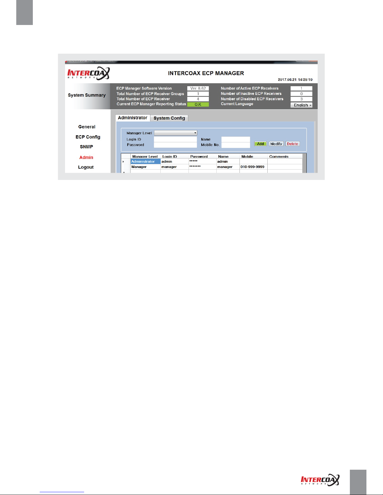
4-4-5 Admin Window
4-4-5-1 Administrator
• The initial administrator ID & Password is set to “ admin” and you will need to configure the password
in the admin window.
• The administrator has full access to all users.
• The administrator account cannot be deleted.
• Please change the password every three months to safely protect admin information and prevent the damage
of the information theft.
- Manager level: Select the user level. The Only administrator is allowed to create new account ID and Password.
- Login ID: Change the admin ID
- Password: Enter new password
- Name: Enter personal name or number if necessary.
- Mobile No.: Enter phone number of the user if necessary
- ADD / Modify / Delete Buon is used to add, modify and delete the Login information
Page 37
Network Solution ProviderPage 37 of 41
High-Speed, Long distance Ethernet and PoE Extender
4-4-5 Admin Window
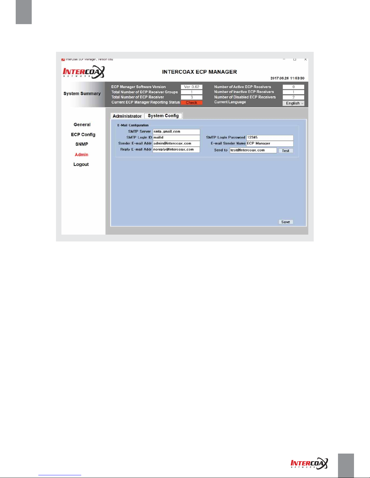
4-4-5-2 System Config
On System Config menu, the user can configure e-mail server to send the device status to a registered recipient.
- SMTP server: Enter the SMTP server address to connect to.
- SMTP Login ID: Enter a ID to use authentication when connecting to the SMTP sever.
- SMTP Login Password: Enter the user's password of the SMTP server.
- Sender E-mail Addr: Enter the sender’s e-mail address.
- E-mail Sender name: Enter the email sender’s name.
- Reply E-mail Addr: Enter the email address wish to receive replied emails
- Send to: Enter the email address of recipient.
- Test button: Conducts the test on the server setting.
- Save button: Save the configuration.
Page 38
Network Solution ProviderPage 38 of 41
High-Speed, Long distance Ethernet and PoE Extender
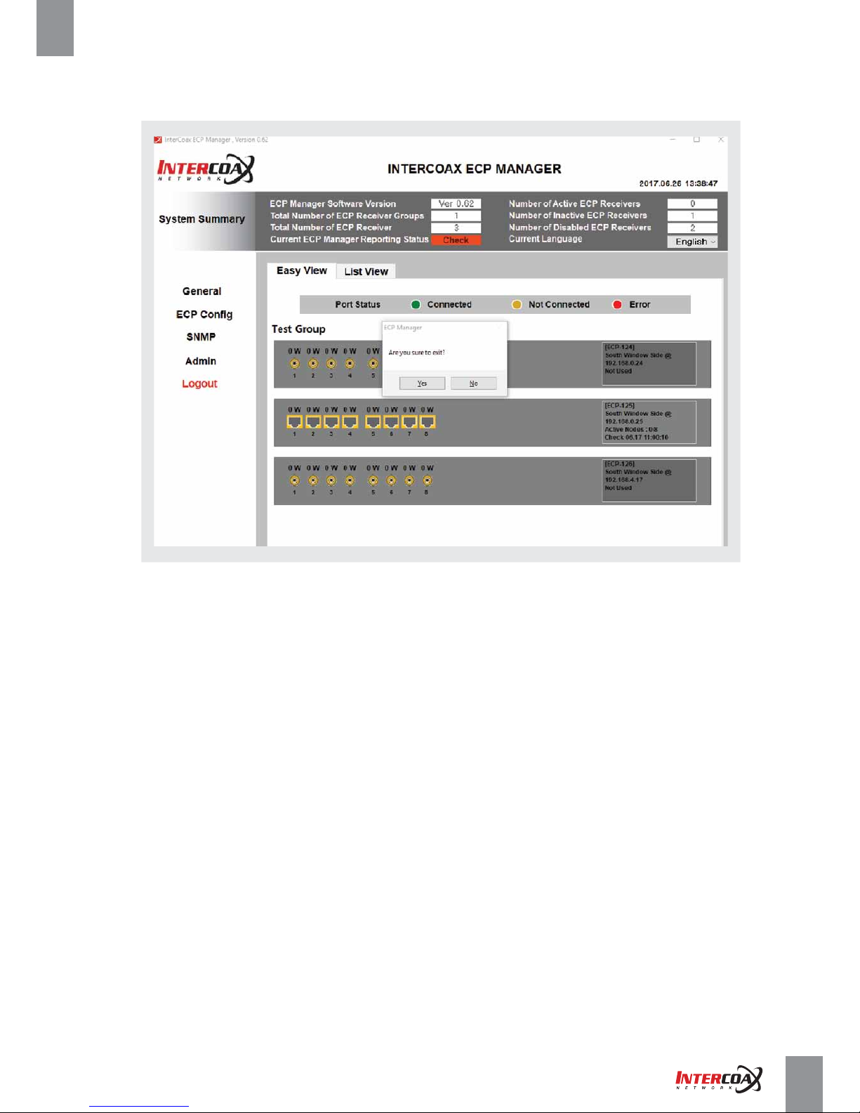
4-4-6 Logout Window
• Logout and close the ECP Manager Software
Page 39
Network Solution ProviderPage 39 of 41
High-Speed, Long distance Ethernet and PoE Extender
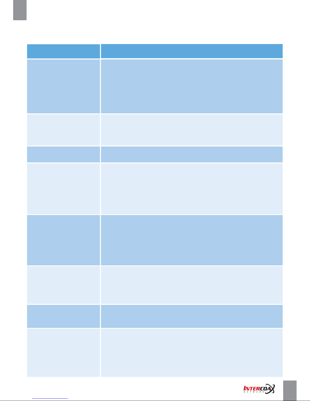
5. Troubleshooting
5-1. Hardware
Problem
Action
. Check if the power supply system is properly connected.
. Check if coax / UTP cable is connected properly.
. Check if B-Linx / T-Linx Port LED is ON.
. Check if the network port is properly connected and the network setting is set correctly.
. Check the system for the input voltage from the power source.
. If the problem persists even after you have taken the above actions,
check the other network device settings (e.g. IP camera, NVR, etc)
. Check that the cable length does not exceed transmission distance limitation
of 100 meters.
. Power the transmitter with separate power supply to check it turns on.
. Check that the cable length does not exceed transmission distance limitation
(e.g 500 meters) (Please refer to Specification on Page 13~14)
. Check the cable condition and ensure all BNC / RJ-45 connection are secure.
. Check if there’s any kind of signal booster, noise filter, repeaters,
other amplifiers for the signal on cable, if yes, please remove them before installation
of the devices.
. Check the Coax / UTP cable if it is shorted.
. Check that the network cable is in good condition and has been assembled correctly.
. Confirm if the camera is IEEE802.3af/at PoE Compliant.
. Please check that the Ethernet length does not exceed transmission distance limitation
of 100 meters.
. Check the PoE output Switch on the Transmitter is set to ON.
. Due to power drops on the cable, may need extra 56V power supply on the transmitter.
. Live video will be cut off
. Check if the power supply system is properly connected.
. Check the system input voltage from the power source.
. If the problem persists even after you have taken the above actions,
check power cable and replace it if necessary.
. The system does not turn on
and the power indicator on
the front panel does not work at all.
. Check the Coax / UTP cable if it is shorted.. B-Linx / T-Linx
port Indicator (LED) is blinking
. Check the Coax / UTP cable if it is connected properly.
. Check UTP cable order if it is correct (Cable order should be EIA/TIA-568B Type)
. Check if the password of the Local Node (Receiver)
and Remote Node (Transmitter) is matched.
. If the password of local node(Receiver) and remote node(Transmitter) is not matched
or unknown password is entered, please join the both devices again
(Please refer to Joining configuration on Page 11 and 26)
. Join LED is not ON
. No network connection
. over coax / UTP
. Check that the cable length does not exceed transmission distance limitation
(e.g 500 meters) (Please refer to Specification on Page 13~14)
. Check the cable condition and ensure all BNC / RJ-45 connection are secure.
. Check if there’s any kind of signal booster, noise filter, repeaters, other amplifiers
for the signal on cable, if yes, please remove them before installation of the devices.
. No network connection
from receiver to network switch
or NVR, or transmitter to camera.
. Transmitters are
not turned powered on
. PoE is not enabled
to end-devices even
the transmitter is working properly
Page 40
Network Solution ProviderPage 40 of 41
High-Speed, Long distance Ethernet and PoE Extender
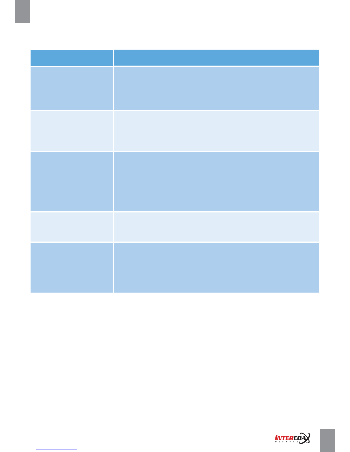
5. Troubleshooting
5-2. Software
Problem
Action
. Press reset button on Power menu of the general window to restart transmitters
and end-devices.
. If the problem persists even after you have taken the above actions, please check
if B-Linx or T-Linx LED of the front panel of the device is blinking => If blinking, please
check the cable and BNC condition.
. Green Color is displayed
on the port status of the device
GUI of the general menu.
. Press reset button on Power menu of the general window to restart transmitters
and end-devices.
. Some or several remote nodes
are not displayed as connected.
. ECP Manager Lite: press F4 button for refresh the window
. ECP Manager: press Refresh
. Check if the MAC addresses of the receiving switch match the MAC addresses on the
serial label => If not, please contact to distributor or manufacturer.
. Proceed with the joining again. (Please refer to the page 11 and 26)
[Note] When joining, password changes can take up to 60 seconds.
. There’s no devices displayed
in Join and node control menu
. Check IP address of the PC first, change the IP address as 192.168.4.100 => Press reset
button on the front panel of the receiving switch for more than 15 seconds until the
alarm LED is turn on after blinking => Device’s IP will be changed as 192.168.4.17
(default IP address) => try to connect the device again from PC.
. Unknown IP address is entered
on the receiving switch.
. Check if IP address of the PC and Receiving switch is set correctly.
. Please check that the cable length does not exceed transmission distance limitation
of 100 meters.
. Check network cable connection and condition of RJ-45 connector
. Network connection is fail.
. “Check” massage is displayed
on current ECP Manager reporting
status of System summary.
Page 41
Network Solution ProviderPage 41 of 41
High-Speed, Long distance Ethernet and PoE Extender
6. Warranty Policy
Intercoax Co.,Ltd. warrants that the product conforms to Intercoax’s applicable published specifications
and it free of defects for 24 months from the date of purchase.
Warranty will only be provided for the product purchased from an Intercoax authorized selling agent.
Defective product will be repaired, replaced or substituted with a product of equal value by Intercoax’s option.
This warranty will not be covered for any damages or breakage from user’s abuse, accident, modification
of the device, natural disaster, product fails due to damage from shipment, handling, storage or misuse.
Intercoax’s liability under any warranties shall be discharged by replacing or repairing any part or parts which do
not conform to the applicable warranty under normal and proper use.
Intercoax’s liability with respect to any product shall not exceed a refund of the price received by Intercoax
for that product, and in no event shall Intercoax have any liability for any incidental, consequential, special, or
indirect damages.
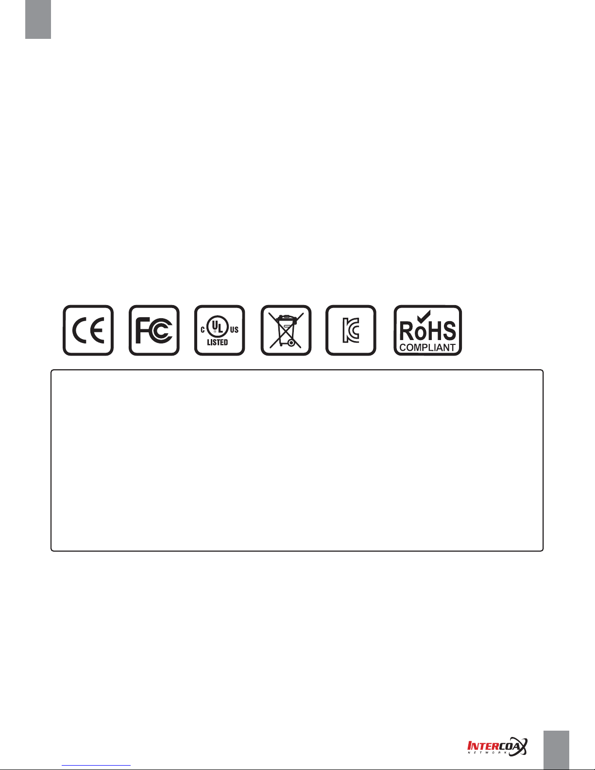
7. Regulatory and Certificates
8. Customer supports
Intercoax Co.,Ltd (Korea Head Office)
Address: 51, Simin-daero 365, Dongan-gu, Anyang-si, Gyeonggi-do, Korea (14057)
Tel: +82-31-365-3133 Fax: +82-31-365-3135
For all general requests: [email protected]
For all Asia Pacific requests: [email protected]
For all EMEA requests: [email protected]
For all North America requests: [email protected]
Web: www.intercoax.com
INFORMATION TO THE USER
This equipment has been tested and found to comply with the limits for a Class A digital device, pursuant to part 15
of the FCC Rules. These limits are designed to provide reasonable protection against harmful interference when the
equipment is operated in a commercial environment. This equipment generates, uses, and can radiate radio frequency
energy and, if not installed and used in accordance with the instruction manual, may cause harmful interference to
radio communications. Operation of this equipment in a residential area is likely to cause harmful interference in
which case the user will be required to correct the interference at his own expense.
WARNING
Any changes or modifications not expressly approved by the manufacturer could void the user’s authority to
operate the equipment.
 Loading...