

Intercoax ECP-2601T, ECP-2601R Quick Start Manual
Quick Start Guide
ECP-2601T / ECP-2601R
Please read carefully the instruction manual before use. Depending
on the model, the image and the actual look of the product may vary.
Overview
This device is a High-Speed, long distance Ethernet & PoE extender
that makes possible to transmit the Ethernet signal up to 2.4Km and
PoE up to 1.2Km via Coax (or UTP, 2-wire) cables in different situations.
It is cost-effective and time saving solution to migrate existing analog
system to IP based system since this device supports easy installation
utilizing the existing cable.
With long distance transmission feature, the device makes to
overcome 100 meters distance limitation easily and reduces the
construction cost significantly compared with fiber optic configuration.
[Rev.1.0]
Package
ECP-2601T (Transmitter)
ECP-2601R (Receiver)
Bracket Quick Start
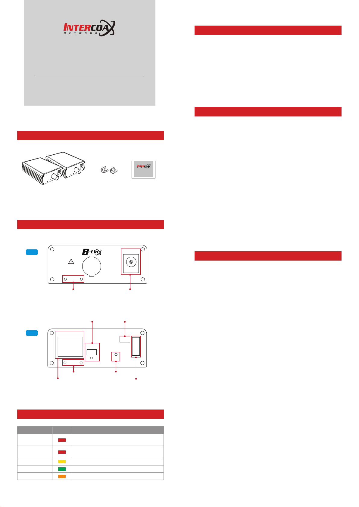
Hardware Overview
Right
NO ANALOG
CAMERA
Bracket
브라켓 홀
Bracket Hole DC Power Jack
PoE ON/OFF Switch
Left
PoE ON/OFF 스위치
(ECP-2601T only)
(ECP-2601T 전용)
ETHERNET
PoE
ON OFF
Bracket
브라켓 홀
Bracket Hole Join Button
RJ45
PoE-ON (ECP-2601T)
PD-AUX (ECP-2601R)
Join
Join 버튼
Status LED Indicator
LED Indicators
Indicator Color Function
PoE-ON (Tx)
PD-AUX (Rx)
Data-Link
Join-Link
Power
ON : PoE Switch On (PoE Output)
OFF : PoE Switch Off
ON : PoE Input or Powered by Transmitter
OFF : Powered by adapter
Blinking : Ethernet Data Act
ECP-Product Link
56V DC Link
56V DC
DC 전원 어댑터
PoE-ON
Data-Link
Join-Link
Power
상태 표시등
Guide
Features
Ethernet over Coax communication following IEEE1901 Standard
Data + Power over Coax cable (or UTP, 2-Wire)
Data distance up to 2.4Km
PoE distance up to 1.2Km
Max. 95Mbps Bandwidth
(270Mbps between Intercoax 2 series models)
10/100 Full Duplex
128bit AES network encryption
Supports Multi-connection (Daisy chain, Star, etc.)
PoE, PoE+, Extra PoE (Max. 60W output)
Supports UTP, Telephone (2 Pairs), 2-Wire cable communication
(Using BTE Series)
LED Indication (Data, Power, Link, PoE)
Plug & Play
Surge Protection
Support PoE+ Input (25.5W) from PSE devices – ECP-2601R Only
Slim design
Installation Guide
1. Set the IP address on the camera following the instruction manual
of the camera.
Î
If the camera IP is automatically assigned (DHCP, etc.), there is no
need to set the camera IP separately.
2. Connect BNC of the coaxial cable to each
3. Connect 56V DC power to
Transmitter/Receiver
AC outlet.
Î
Receiver
can be powered by PoE Switch Device (PoE+ PD
Supported) but for safe working, it recommeded to use 56VDC
Power supply on
Receiver
. When using both PoE switch Device and
power supply at the same time, power supply works preferentially.
Î
In case of 7W camera, the device supports long distance PoE
transmission up to 1,200m over RG6 coaxial cable.
PoE transmission distance can be varied depending on cable type
and Camera’s power consumption(W).
4. When they are connected without any problem, Power / Join Link
LED are on.
5. Adhere the brackets in the package to
then fix up the products.
6. Connect the UTP(LAN) cable between
then between
7. Turn on the PoE switch on
Transmitter
and camera.
Transmitter
camera is powered by a separate power source (not powered by
PoE output feature of the
Transmitter
Î
Both
connector.
.
Transmitter/Receiver
Receiver
Transmitter
send data and power together via BNC
does not have PoE support so that it can send
data only via RJ45.
8. Ping test is recommended to confirm the whole network after
installation.
9. Check the video signal on the monitor.
Transmitter/Receiver
first and then to
Transmitter/Receiver
Receiver
and NVR first and
and
for PoE IP camera and if the
), turn off the PoE switch on
.
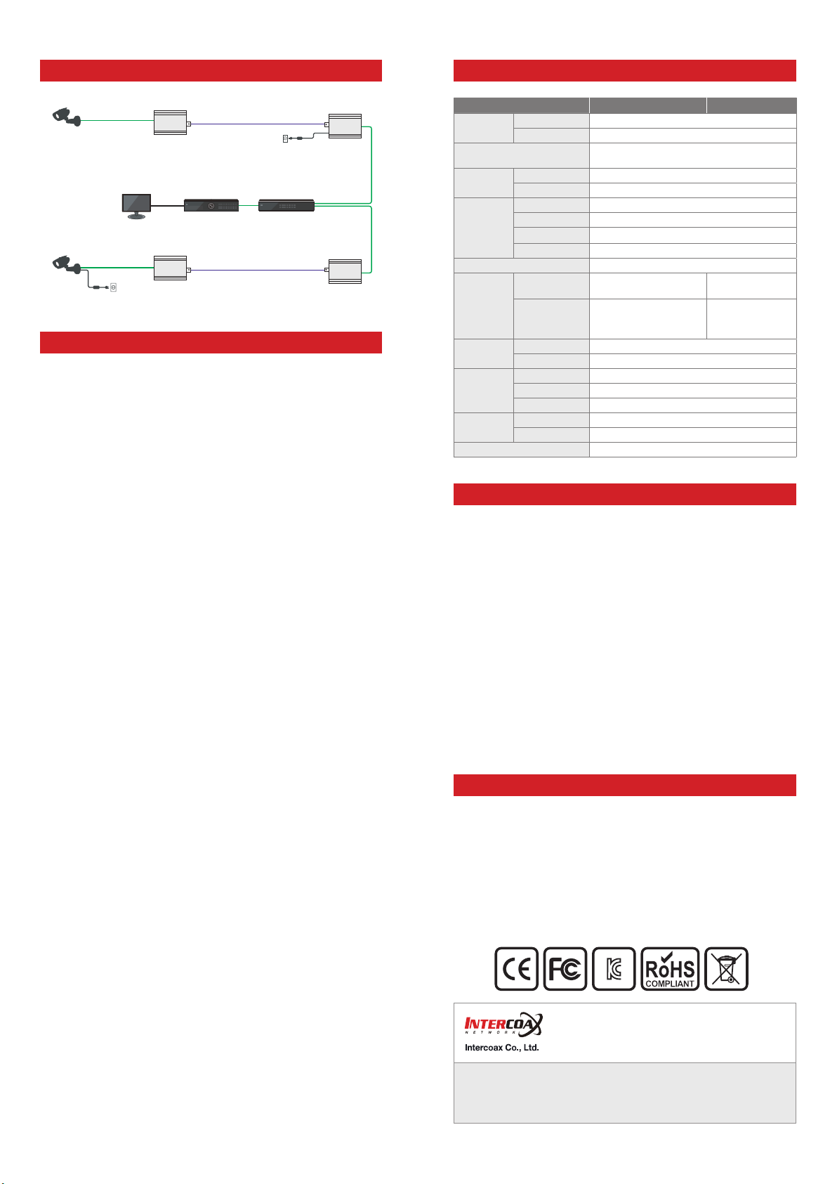
Applications
Specification
10/100 Ethernet
PoE
Camera
Non-PoE IP
Camera
PoE
10/100 Ethernet
AC/DC
Adapter(12V)
ECP-2601T
ECP-2601T
How to change the communication password
NVR
Coaxial Cable
Coaxial Cable
56V DC/1.2A
Power Supply
PoE Switch
(Coax/UTP/2-Wire)
ECP-2601R
ECP-2601R
All Intercoax EoC converters have the same password as factory
defaults setting value and can be used immediately when connecting
to the product (Plug & Play mode).
However, if a number of products are mixed in the same area or
the signal transmission line is in poor condition, the communication
passwords for each equipment (or group) can be set differently to
prevent cross-talk between the lines.
Needed items for Joining
1.
EoC Converters / Power supply / Short Cable (Coax, UTP, 2-Wire) /
Paper clip
Product configuration
2.
a. Connect EoC Converters with Coax cable (or UTP, 2-Wire) and
power to the one of the converters up with power supply.
b. Check if the Power LED on both devices is ON.
Remove the existing password (Unjoining)
3.
This process removes passwords that are entered as factory
defaults.
a. Press the Join button on one of the connected products using a
paper clip until the Power LED turns off and on (Approximately
15 seconds)
b. Remove the existing password by pressing the Join button on the
opposite product in the same way as above.
c. Join LED will be turned off if the password on the devices is
removed correctly.
Create New Password (Joining)
4.
New password for communication between connected devices is
created and this will block the communication with other devices (or
group) which have a different password.
a. Press the Join button for 2 seconds on one of the connected
product using a paper clip and the Join LED of the device will
flicker at a constant speed. (Stand-by mode)
b. Press the Join button for 2 seconds on the opposite device in the
same way as above. And then, the Join LED of the device flickers
at a constant speed and both devices restart at the same time.
c. Then the Join-Link lights up and communications are resumed
between the products
When adding new products in 1:N configuration to a group that
5.
has already been joined. (Group Joining)
a. Connect new device to the group which is already joined. (using
T-BNC or Y-UTP coupler, Terminal block)
b. Remove the password of the new device in the same way as step
‘3-a’.
c. Press Join button on the one of the device of the existing group
for 2 seconds and Join LED flickers at a constant speed.
d. Press Join button on the new device for 2 seconds and new
device restarts
e. Join-Link lights up and communications are resumed between
the products.
Model ECP-2601T ECP-2601R
Interface
Transmission Rate
Transmission
Distance
LED
Indication
Power
Mechanical
Environment
Compliance
Optional Accessories 56VDC / 1.2A External Power Supply
Coax 1 x 75Ω BNC (Female) - Ethernet over Coax (B-LinX)
Ethernet 1 x RJ45 - 10/100 Base-T with Auto-detect MDIX
95Mbps Full Duplex
(270Mbps between Intercoax devices)
Ethernet up to 2.4Km(RG-6)
PoE (PoC) up to 1.2Km (RG-6 / 7W camera)
Ethernet 1 x Data-Link (Yellow)
EoC 1 x Join-Link (Green)
Power 1 x Power On(Amber)
PoE 1 x PoE Out (Red)
Encryption 128-bit AES
Input B-Linx or DC12V~57V
PoE Output
Dimension 82.4(L) x 61.6(W) x 24(H)mm
Weight 77g
Operating Temp -20 ~ 60°C
Storage Temp -30 ~ 80°C
Relative Humidity 10% ~ 90%
Certification FCC, CE, KC
Surge Protection IEC 61000-4-5 4kV(1.2 / 50us), 2kA(8 / 20us)
IEEE802.3af(PoE),
IEEE802.3at (PoE+),
Extra PoE up to 60W
PoE Switch or
DC12V~57V
PoE Not Supported
PoC Only
Caution
Please install the device following the installation guide.
Do not touch the device and cable with wet hands.
Keep away from moisture and shock.
Do not install near any heat sources such as radiators, heat registers,
stoves or other apparatus that produce heat.
Indoor use only.
Do not use for other purposes.
Do not disassemble or modify this device.
Do not put any sticker or paint on it.
If this device is defective or malfunctioning, please unplug the power
adapter immediately and contact dealer or service center.
Please use the rated power supply for the product.
Connect DC power to this device first and then to AC outlet.
Warranty
This device has passed the quality control and product inspection.
Please install and use according to the installation guide.
The warranty period for this product is 24 months from the date of
purchase.
If this device is defective or malfunctioning, please unplug the power
adapter immediately and contact dealer or service center.
Any damages or breakage from user’s abuse, accident, modification
or natural disasters will not be covered manufacturer’s warranty.
Please visit below website for more detailed information.
Web: http://www.intercoax.com Tel: +82. 31. 365. 3133~4
E-mail: info@intercoax.com Fax: +82. 31. 365. 3135
This device complies with part 15 of the fcc rules. Operation is subject to the
following two conditions :
(1) This device may not cause harmful interference, and
(2) This device must accept any interference received including interference
that may cause undesired operation
 Loading...