

Intercoastal CFL-420RB, CFLM-425BM, CFL-42BN, CFNL-420RB, CFNL-42BN Owner's Manual And Installation Instructions
...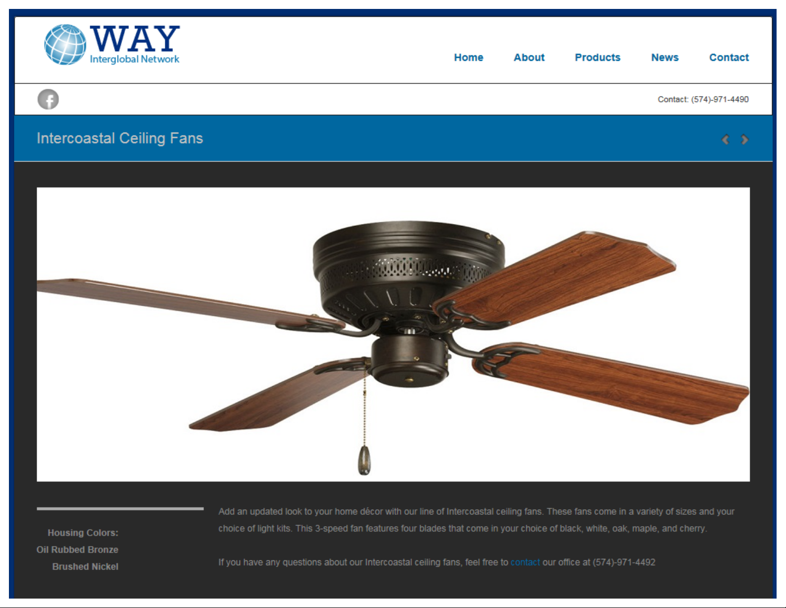

CFL-420RB/CFL-42BN
CFNL-420RB/CFNL-42BN
CFLM-4250RB/CFLM-425BM
.
-
1-
4 :
__,,,,.,,,,.,,,,__-.-..---
I : 2;.
-:.-;
'l.;{i
'
'
'
Owners
Manual
and
Installation Instructions

-
Make
in
order
All
Make
Fan
It
should
Fan
The
marked•acceptable
for
ceiling
acceptable
electrician.
sure
to tum off
to
avoid
electrical
sure
should
be a minimum
should
outlet
fan
for
possible
wiring
the
fan
be
not
box must
installation. You
fan
Your
dealer
mounted a minimum
support.If
electricity
must
is
electricaUy
of
be
mounted
be
for
fan
will
electrical
conform
20 1inches
in
an
able
to
support"
may
you
have
have
the
at
main
switch
shock.
to
national
grounded
of 7 feet
from
any
area
where
support a minimum
.Plastic
use
necessary
outlet
your
existing
any
doubts,check
before
and
to
avoid
above
wall
to
it
might
boxes
products
local
the
box
wiring
Electrical
possible
the
blade
become
weight
are
as
with a qualified
for
or
electrical
floor
to
tip.
of
50lbs.and
not
recommended
long
as
safe
servicing
Codes.
the
fan
wet.
it
is
installation
fan
shock.
blade
of
your
fan.
Never
ceiling.
For
qualified
attach
Do
not
safety
electrician assemble
WARNING!
BEND
BALANCING
FOREIGN
THE
BLADE
OBJECTS
WARNING!
OR
PERSONAL
the blades
operate
and
best
TO
CARRIERS
THE
BLADES,OR
TO
REDUCE
IN
JURY,MOUNT
to
your
your
ceiling
operating
and
REDUCE
IN
BETWEEN
ceiling
fan
before
results,
install
THE
RISK
WHEN
CLEANING
THE
INSTALLING
ROTAONG
RISK
THE
fan
before
the
we
recommend
your
fan.
OF
PERSONAL
THE
OF
FIRE,ELECTRICAL
FAN
TO
the
blades
THE
FAN.DO
FAN
BLADES.
AN
OUTLET
fan
is
mounted
are
installed.
that
you
have
INJURY,00
BRACKETS,
NOT
INSERT
SHOCK,
BOX
to
a
NOT
the
MARKED"ACCEPTABLE
FOR
FAN
SUPPORT".
2

FIGURE
1
STEP
1
MOUNTING
BRACKE
STEP2
Re
mo
e the
temporary
a
the
other
fall
Secure
provided.Align
housing
bracket.
Se&Figure2
and-freewirlng,while holding
otor
unit
upward.Insert on.e
motor
mounting
other
and
of
slot
in
mounting
motor mounting
into
place
In
tightly
with
with
the
Then
T
screws
bracket Into
motor
mounting
plate a
until
tabs
mounting
screws
the 4 holes
holes
on
attach
screws provided.
end
the
nd
on
each
pla
te
and
washers
on
the
the
mounting
Installed
of
the
slot
and
into
the
adjust
side
slot.
motor
Secure
screws
securely
the
to
the
bracket
provided
.
There
bracket
~.__MOUNTING
and
FIGURE2
to
the
with the
should
outlet
box.See
ceiling
outlet
be
no
ouUet
box
box
attach
movement
Figure1
.
using
between
BRACKET
3
FIGURE
3.
Attach
4.Each
plastic
3
the
of
the
wire
white
above
nul
u
wire
fron the
connections
Then
fold
II.
MAKING
fan
the
connected
ELECTRICAL
CONNECTIONS
to
the
should
WARNING:
1.
Attach
wire
In
tile
2.
Attach
the
black
white
wire
be
made
as
wire
and
push
DISCONNECTPOWERHIH
the
green
junction
the
black
wire
in
in
the
junction
light
as
inside
wire
form
box.
wire
and
the
junction
box.
possible
the
junction
the
fan
to
the
blue
wire
from
box.
using a proper
box.
ground
the
size
fan
to

(A] 1
HA
GING
BRACKETS
(BJ
(C) 1 SWITCH HOUSINGASSEMBLY
(OJ
(EJ
1 FAN
1
MO
1
FAN KIT
(F)
MOTOR
TOR HOUSING
(GI
FI
(f)
GURE
4 FAN
1
~
FIGURE2
(GJ
4 BLADES HOLDERS
BLADES
(ff) 1
CONTAINS:
HARDWAREBAG
a 2
b 2
c 13
d
13
e 3
f 2
g 9
--------===Clil"I~
WOOD
HOUSINGSCREWS~
BLADE
FIBER
WIRE
FAN
BLADE
SCREWS
SCREWS
WASHERS
NUTS
PULL
TASSEL------•
HOLDER
-----
SCREWS
( I I 1 BALANCING KIT
______.
------
(1
...
0
•
•
..
O-
.
..
BAG)
4

OPTIONAL
WALL
SWITCH
WIRING DIAGRAMS
FI
GURE4
SWITCH TO
CONTROL LIGHT
LIGHT&
(2
WALL
FAN
FIGURES
FAN
SWITC
BLADE
Attach the tan blade to blade holder using screws and washers
suppiled . Tighten each screw starting with the
sure the blade Is straight.Fasten the blade and assembly to the
mot
NOTE:THE
BALANCED
CAREFUL
HES)
TO
or using
WALL
SWITCH
BLADE
the
screws supplied.See fiaure6
BLADE
NOTTO
TO
AVOID
HOLDERS
BEND
HOLDERASSEMBLY
AND
WOBBLING
OR
DAMAGE
BLACK
BLADES
WHEN
THE
THEM.
JUNCTION
center
HAVE
BEEN
FANIS
BOX
OPERST1NG.BE
BLACK
screw making
CAREFULLY
5
 Loading...