

Page 1
MAGICLIGHT®
MAGICLIGHT®
Bedienungsanleitung
Operating Guidelines
03 / 2018
Page 2

Bedienungsanleitung MAGICLIGHT®
Operating Guidelines MAGICLIGHT®
Deutsch . . . . . . . . . . . . . . . . . . . . . . . . . . . . . . . . . . . . . ab Seite 3
English . . . . . . . . . . . . . . . . . . . . . . . . . . . . . . . . . . . from page 35
Page 3

Inhalt
1. Einleitung � � � � � � � � � � � � � � � � � � � � � � � � � � � � � � � � � � � � � � � � � � � � � � � � � � � � � � 5
2. Medizinische Anforderungen / Anwendungsgebiet � � � � � � � � � � � � � � � � � � � � 5
3. Allgemeines � � � � � � � � � � � � � � � � � � � � � � � � � � � � � � � � � � � � � � � � � � � � � � � � � � � � 6
4. Übersicht Baugruppen � � � � � � � � � � � � � � � � � � � � � � � � � � � � � � � � � � � � � � � � � � � 7
5. Kombinationsmöglichkeiten � � � � � � � � � � � � � � � � � � � � � � � � � � � � � � � � � � � � � � � 8
6. Technische Daten � � � � � � � � � � � � � � � � � � � � � � � � � � � � � � � � � � � � � � � � � � � � � � � � 8
7. Sicherheitshinweise � � � � � � � � � � � � � � � � � � � � � � � � � � � � � � � � � � � � � � � � � � � � � 9
8. Hinweissymbole � � � � � � � � � � � � � � � � � � � � � � � � � � � � � � � � � � � � � � � � � � � � � � � � 10
9. QuickGuide � � � � � � � � � � � � � � � � � � � � � � � � � � � � � � � � � � � � � � � � � � � � � � � � � � � � 11
10. Bedienung / Einstellung / Montage � � � � � � � � � � � � � � � � � � � � � � � � � � � � � � � � � 12
10�1 Trapezadapter � � � � � � � � � � � � � � � � � � � � � � � � � � � � � � � � � � � � � � � � � � � � � � � � � � 12
10�2 Werkzeug � � � � � � � � � � � � � � � � � � � � � � � � � � � � � � � � � � � � � � � � � � � � � � � � � � � � � � 12
10�3 Sitzschale/Einstellschrauben � � � � � � � � � � � � � � � � � � � � � � � � � � � � � � � � � � � � � 13
10�4 Einstellen der Sitzschale � � � � � � � � � � � � � � � � � � � � � � � � � � � � � � � � � � � � � � � � � 13
10�5 Rückenlehne/Rumpfführungspelotten � � � � � � � � � � � � � � � � � � � � � � � � � � � � � � 16
10�6 Rückenlehne/Rückenhöhe � � � � � � � � � � � � � � � � � � � � � � � � � � � � � � � � � � � � � � � � 17
10�7 Rückenlehne/Neigung � � � � � � � � � � � � � � � � � � � � � � � � � � � � � � � � � � � � � � � � � � � 18
10�8 Rückenlehne/Kopfstütze � � � � � � � � � � � � � � � � � � � � � � � � � � � � � � � � � � � � � � � � � 18
10�9 Becken-Sicherheitsgurt � � � � � � � � � � � � � � � � � � � � � � � � � � � � � � � � � � � � � � � � � � 19
10�10 Rückenlehne/ Brustschulterpelotte � � � � � � � � � � � � � � � � � � � � � � � � � � � � � � � 20
10�11 Rückenlehne/Gurtführung � � � � � � � � � � � � � � � � � � � � � � � � � � � � � � � � � � � � � � � 21
10�12 Armauflagen � � � � � � � � � � � � � � � � � � � � � � � � � � � � � � � � � � � � � � � � � � � � � � � � � � � 21
10�13 Fußbretter � � � � � � � � � � � � � � � � � � � � � � � � � � � � � � � � � � � � � � � � � � � � � � � � � � � � 22
11. Täglicher Gebrauch � � � � � � � � � � � � � � � � � � � � � � � � � � � � � � � � � � � � � � � � � � � � 23
11�1 Rückendynamik � � � � � � � � � � � � � � � � � � � � � � � � � � � � � � � � � � � � � � � � � � � � � � � � 23
11�2 Liegeposition � � � � � � � � � � � � � � � � � � � � � � � � � � � � � � � � � � � � � � � � � � � � � � � � � � 23
12. Optionales Zubehör � � � � � � � � � � � � � � � � � � � � � � � � � � � � � � � � � � � � � � � � � � � � 24
12�1 Oberarmbegrenzungen � � � � � � � � � � � � � � � � � � � � � � � � � � � � � � � � � � � � � � � � � 24
12�2 Therapietisch, klettbar � � � � � � � � � � � � � � � � � � � � � � � � � � � � � � � � � � � � � � � � � 24
12�3 Therapietisch, aufsteckbar � � � � � � � � � � � � � � � � � � � � � � � � � � � � � � � � � � � � � � 24
12�4 Kopfstütze, Standard � � � � � � � � � � � � � � � � � � � � � � � � � � � � � � � � � � � � � � � � � � � 25
12�5 Fußbank � � � � � � � � � � � � � � � � � � � � � � � � � � � � � � � � � � � � � � � � � � � � � � � � � � � � � 25
12�6 Fußbankpolsterung � � � � � � � � � � � � � � � � � � � � � � � � � � � � � � � � � � � � � � � � � � � � 25
12�7 Fußfixierungen � � � � � � � � � � � � � � � � � � � � � � � � � � � � � � � � � � � � � � � � � � � � � � � � 26
13. Typenschild � � � � � � � � � � � � � � � � � � � � � � � � � � � � � � � � � � � � � � � � � � � � � � � � � � � 26
14. Wartung / Kontrolle � � � � � � � � � � � � � � � � � � � � � � � � � � � � � � � � � � � � � � � � � � � � 27
15. Serviceplan � � � � � � � � � � � � � � � � � � � � � � � � � � � � � � � � � � � � � � � � � � � � � � � � � � � 28
16. Material / Reinigung / Pflege � � � � � � � � � � � � � � � � � � � � � � � � � � � � � � � � � � � � � 29
Deutsch
3
Page 4

17. Konformitätserklärung � � � � � � � � � � � � � � � � � � � � � � � � � � � � � � � � � � � � � � � � � 30
18. Garantie � � � � � � � � � � � � � � � � � � � � � � � � � � � � � � � � � � � � � � � � � � � � � � � � � � � � � � � 31
19. Wiedereinsatz � � � � � � � � � � � � � � � � � � � � � � � � � � � � � � � � � � � � � � � � � � � � � � � � � � 32
20. Entsorgung � � � � � � � � � � � � � � � � � � � � � � � � � � � � � � � � � � � � � � � � � � � � � � � � � � � � 32
4
Page 5

1. Einleitung
Vielen Dank, dass Sie sich für ein Qualitätsprodukt aus dem Hause interco entschieden haben! Wir wünschen Ihnen viel Freude und therapeutische Erfolge bei
der Benutzung unseres Produktes� Sollten Sie Fragen haben, zögern Sie nicht,
uns zu kontaktieren�
Das Produkt ist in einem Temperaturbereich von -20° C bis +60° C (-4° F bis
+140° F) getestet worden� Zwischen den einzelnen Fertigungspartien lassen
sich Farbunterschiede nicht immer vermeiden� Diesbezügliche Reklamationen
können leider nicht anerkannt werden� Bitte haben Sie Verständnis dafür, dass
unsachgemäße Behandlung, eventuelle Regenränder oder Farbunterschiede im
Stoff, wie oben beschrieben, keine Reklamationen darstellen�
Bitte beachten Sie, dass nur durch die genaue Handhabung dieser Bedienungsanleitung Schäden, Fehler oder Verletzungen vermieden werden können� Machen Sie sich vor dem ersten Gebrauch mit der Handhabung und Funktion des
Produktes vertraut und üben Sie zunächst den richtigen Umgang�
Diese Bedienungsanleitung ist zum späteren Gebrauch aufzubewahren�
Bitte notieren Sie sich die Bestellnummer, die Sie auf der Rückseite dieser Bedienungsanleitung finden und legen Sie die Nummer an einem sicheren Ort ab�
Bei Verlust der Bedienungsanleitung können Sie dann problemlos eine neue
anfordern� So ist gewährleistet, dass Fehler und Schäden bei der Einstellung
und Bedienung von MAGICLIGHT sowie Verletzungen des Patienten vermieden
werden�
Deutsch
Eitorf, 07 / 2013 · Technische Änderungen vorbehalten
2. Medizinische Anforderungen / Anwendungsgebiet
Das Sitzsystem MAGICLIGHT wird eingesetzt bei:
Ausgeprägten Bewegungsstörungen oder Lähmungen mit gleichzeitig verminderter Rumpf- und Kopfstabilität, die das Sitzen mit umfassenden Unterstützungen notwendig machen; Fehlbildungen durch Krankheiten/Behinderungen
oder Deformitäten des Rumpfes, die aufgrund der abnormen Form des Körpers
ein Sitzen mit speziellen Stütz- und Fixierungsmöglichkeiten erfordert�
MEDIZINISCHE ANFORDERUNGEN / ANWENDUNGSGEBIET 5
Page 6

MAGICLIGHT kommt außerdem zum Einsatz bei z. B.:
Celebralen Bewegungsstörungen
Myelodysplasie
Muskeldystrophie oder -atrophie
Multipler Sklerose
Schwerwiegenden Fehlbildungen des Rumpfes und/oder anderer
Extremitäten,wie Hüfte oder Knien
Kontraindikationen sind nicht bekannt�
Bitte beachten Sie: Eine Gewährleistung von uns kann nur übernommen werden, wenn das Produkt unter den angegebenen Bedingungen und vorgesehenen
Zwecken eingesetzt wird�
3. Allgemeines
MAGICLIGHT ist ein vielseitiges, dynamisches Sitzsystem, aus leichten Aluminiumschalen gefertigt und mit einer anatomischen Grundpolsterung ausgestattet� Durch seine individuelle Einstellmöglichkeit in der Sitzbreite, Sitzlänge und
Sitzhöhe garantiert es eine ideale Anpassung sowie ein Mitwachsen des Sitzsystems mit dem kleinen Patienten� Alle Grundkomponenten von MAGICLIGHT
sind variabel einstellbar, an die Bedürfnisse des Patienten angepasst und bieten
so gute Seitenführung sowohl für Oberkörper als auch für Becken und Beine�
Die Sitz-Rückeneinheit von MAGICLIGHT ist über Drehpunkte miteinander verbunden� Die Rückenlehne ist beweglich und kann so die plötzlich aufkommende
Energie beim Strecken des Patienten gut absorbieren� Nach der Streckung wird
der Patient wieder in die ursprüngliche Position zurückgebracht� Der Winkel
der Rückenlehne lässt sich bis zu 30° neigen, um eine entspannte Liegeposition
bieten zu können� Das ganze Konzept von MAGICLIGHT ist auf Leichtigkeit und
Luftzirkulation ausgelegt� Hochwertige Polsterstoffe garantieren eine lange
Lebensdauer, sind leicht zu reinigen und waschbar� Durch optionales Zubehör
erreicht man eine hohe Variabilität und Flexibilität, die eine ideale Anpassung an
den Patienten garantiert� MAGICLIGHT wird von Ihrem Fachbetrieb individuell
an den Patienten angepasst und vormontiert geliefert� Nach dem Entfernen der
Transportverpackung können Sie Ihre neue MAGICLIGHT sofort einsetzen� MAGICLIGHT ist je nach Untergestell sowohl im Innen- als auch im Außenbereich
einsetzbar� Zur besseren Darstellung in dieser Bedienungsanleitung ist MAGICLIGHT auf das Untergestell ROOMY NEW EDITION montiert, welches aber nicht
zum Lieferumfang gehört�
6 ALLGEMEINES
Page 7
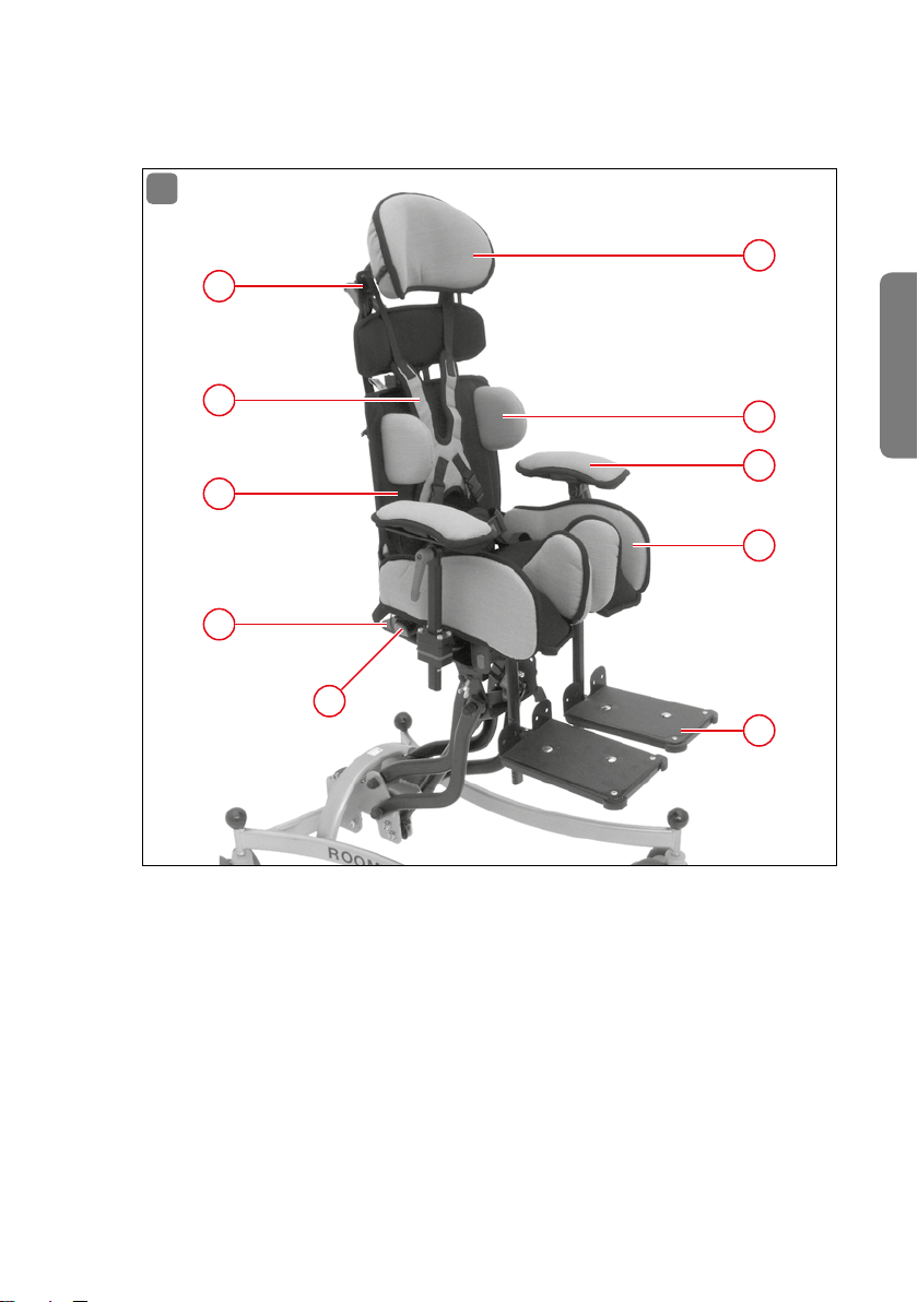
4. Übersicht Baugruppen
1
10
1
9
8
7
6
1 Kopfstütze
2 Rumpfführungspelotten
3 Armauflagen
4 Sitzschale
5 Fußbretter
6 Trapezadapter
7 Beckengurt
8 Rückenlehne
9 Brustschulterpelotte
10 Gurtführungen
Deutsch
2
3
4
5
ÜBERSICHT BAUGRUPPEN 7
Page 8

5. Kombinationsmöglichkeiten
MAGICLIGHT lässt mit folgenden Untergestellen kombinieren:
Für den Innen- und Außenbereich
ROOMY NEW EDITION (12˝ / 16˝ Räder)
SIMPLY LIGHT
SIMPLY
MINY
Für den Innenbereich
ROOMY NEW EDITION
ROOMY
6. Technische Daten
Gr. 0 Gr. 1 Gr. 2 Gr. 3
Gewicht komplett ca. 2,5 kg ca. 3 kg ca. 4 kg ca. 7 kg
Max. Belastung 20 kg 25 kg 35 kg 45 kg
Max. Körpergröße ca. 105 cm ca. 120 cm ca. 135 cm ca. 150 cm
Max. Gesamtbreite
außen (ohne Armlehnen)
Abduktionswinkel /
Beinschalen
Gesamthöhe außen,
inkl. Trapezadapter
Rückenwinkel-
verstellung
Sitzbreite 19 - 25 cm 19 - 25 cm 25 - 31 cm 31 - 36 cm
Sitztiefe 16 - 19 cm 19 - 25 cm 25 - 31 cm 31 - 36 cm
Rückenhöhe
(normale Ausführung)
Rückenhöhe
(lange Ausführung)
Höhe Rumpfführungen,
ab Sitzpolster, für
normalen Rücken
36 cm 36 cm 41 cm 46 cm
-10° bis
+25° C
42 cm 42 cm 46 cm 53 cm
-10° bis
+ 3 0 ° C
29 - 35 cm 29 - 35 cm 35 - 41 cm 41 - 47 cm
34 - 40 cm 34 - 40 cm 40 - 46 cm 46 - 52 cm
min. 17 cm
max. 22 cm
-10° bis
+25° C
-10° bis
+ 3 0 ° C
min. 17 cm
max. 22 cm
-10° bis
+25° C
-10° bis
+ 3 0 ° C
min. 22 cm
max. 27 cm
-10° bis
+25° C
-10° bis
+ 3 0 ° C
min. 28 cm
max. 35 cm
8 KOMBINATIONSMÖGLICHKEITEN
Page 9

Gr. 0 Gr. 1 Gr. 2 Gr. 3
Höhe Rumpfführungen,
ab Sitzpolster, für
min. 17 cm
max. 27 cm
langen Rücken
Breite zwischen
Rumpfführungen
min. 13 cm
max. 19 cm
7. Sicherheitshinweise
Beachten Sie stets die Bedienungs- und Sicherheitshinweise des
Untergestells, auf dem Ihre MAGICLIGHT montiert ist�
Ein Transport des Patienten in der Sitzschale im Auto ist zu keiner Zeit
gestattet!
Für den Transport im Auto verwenden Sie bitte spezielle Fahrzeugsitze, die
den geltenden Vorschriften entsprechen� Die Sitzschale darf nur im unbesetzten Zustand im Fahrzeug transportiert werden und muss entsprechend gesichert werden�
Wir weisen ausdrücklich darauf hin, dass Personen in Sitzschalen zu jedem Zeitpunkt mittels geeigneter Rückhaltesysteme (Begurtung) gesichert
sein müssen!
Achten Sie stets darauf, dass die Sitzschale fest mit dem Untergestell verbunden und gesichert ist�
Wenden Sie sich stets an Ihren Fachhändler oder an Ihr interco-Team,
wenn Sie Fragen zu MAGICLIGHT haben�
Unterziehen Sie sämtliche Schraubverbindungen der MAGICLIGHT einer
regelmäßigen Sichtkontrolle� Konsultieren Sie im Zweifelsfall Ihren autorisierten Fachhändler�
Lassen Sie alle notwendigen Modifikationen oder zusätzlichen Anbauten
durch den
Fachhändler ausführen�
Anbau von Zusatzteilen oder Veränderungen an MAGICLIGHT durch andere
als den Hersteller sind nicht zulässig und können bei Bekanntwerden juristisch geahndet werden� Ebenso erlischt hierdurch die Gewährleistungspflicht der Fa� interco GmbH und es bestehen keine Haftungsansprüche
mehr gegenüber dem Hersteller�
MAGICLIGHT ist nur für den bestimmungsgemäßen Gebrauch zugelassen�
Sitzeinheiten dürfen nur in der vorgegebenen Richtung auf das Untergestell montiert werden�
Benutzen Sie zum Ein- oder Aussteigen aus einem Sitzsystem nicht das
min. 17 cm
max. 27 cm
min. 13 cm
max. 19 cm
min. 22 cm
max. 32 cm
min. 18 cm
max. 24 cm
min. 28 cm
max. 40 cm
min. 23 cm
max. 29 cm
Deutsch
SICHERHEITSHINWEISE 9
Page 10

Fußbrett oder die Fußbank� Diese sollte vorher weggeklappt oder abgenommen werden�
Zur Überwindung von Treppen müssen der Patient, das Sitzsystem und das
Zimmeruntergestell getrennt voneinander befördert werden�
Ein Tragen des Zimmeruntergestells mit montiertem Sitzsystem und darin
sitzendem Patient ist unzulässig! Sichern Sie vor allen Hebe- und Senkvorgängen sowie vor Verstellen der Sitzneigung den Patienten vor dem
Herausfallen�
Das Anhängen von Taschen ist unzulässig�
Lassen Sie den Patienten niemals unbeaufsichtigt, auch dann nicht,
wenn er durch Begurtung gesichert ist�
Die Bedienung und Einstellung des Sitzsystems MAGICLIGHT ist für
Personen mit Sehbehinderung nicht gestattet�
Durch Sonneneinstrahlung können sich die Polster und Metallteile von
MAGICLIGHT stark aufheizen und dem Patienten gegebenenfalls
Verbrennungen zufügen�
Vorsicht beim Umgang mit offenem Feuer sowie vor unachtsamen Gebrauch von Zigarren, Pfeifen und Zigaretten� Herunterfallende Glut kann
zum Schwelen der Polster und Bezüge und dadurch zum Brand führen�
8. Hinweissymbole
Bitte beachten Sie die nachfolgend aufgelisteten Achtungssymbole und ihre Bedeutungen� Die aufgelisteten Symbole finden Sie auch auf dem Produkt wieder�
Achtung: Besondere Aufmerksamkeit
Achtung: Nach Benutzung wieder am vorgesehenen Platz positionieren
1
Achtung: Schrauben auf festen Sitz überprüfen,
2
gegebenenfalls nachziehen
Achtung: Einbaulage überprüfen, gegebenenfalls korrigieren
3
Achtung: Hebel auf festen Sitz überprüfen, gegebenenfalls nachziehen
4
10 HINWEISSYMBOLE
Page 11
9. QuickGuide
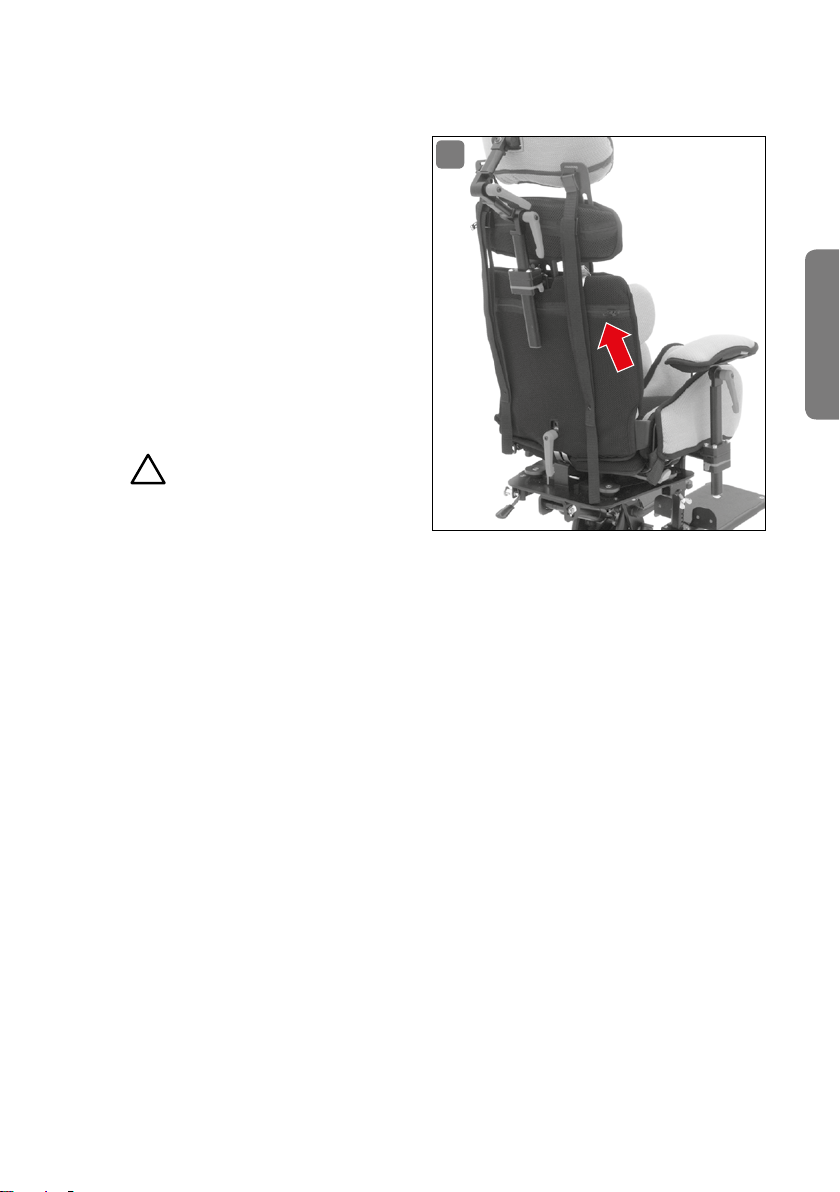
An der Rückenlehne von MAGICLIGHT befindet sich eine Tasche, in
der ein QuickGuide (Abb� 2) aufbewahrt ist�
Dieser QuickGuide ermöglicht dem
Bediener, sich schnell und zuverlässig über die einfachen Verstellmöglichkeiten zu informieren, die
er selber vornehmen kann, ohne
sich an den Fachbetrieb wenden
zu müssen�
Achtung!
1
Um zu gewährleisten, dass die einfachen Verstellmöglichkeiten auch
durch wechselnde Bediener durchgeführt werden können, muss der QuickGuide
immer bei der MAGICLIGHT mitgeführt werden�
Nach der Benutzung muss der QuickGuide wieder in der vorgesehenen Tasche
verstaut werden�
2
Deutsch
QUICKGUIDE 11
Page 12
10. Bedienung / Einstellung / Montage
10.1 Trapezadapter
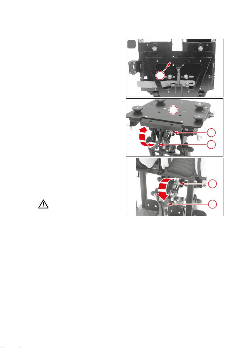
Das Trapezadaptersystem (Abb� 3) ,
bestehend aus Trapezadapter (1)
und Trapezadapteraufnehme (2),
ist die Verbindung von MAGICLIGHT
zu den möglichen Untergestellen
oder Rollstühlen� Zugschnäpper (3)
am Untergestell herausziehen und
um 90° verdrehen, Rastnocken (4)
nach unten ziehen, MAGICLIGHT
von vorne bis zum Anschlag auf das
Untergestell aufschieben� Durch
die Zwangsführung des Trapezadaptersystems wird MAGICLIGHT
genau auf dem Untergestell positioniert� Anschließend den Rastnocken (6) nach oben drücken,
Zugschnäpper (5) wieder um 90°
verdrehen und einschnappen lassen� MAGICLIGHT ist nun auf dem
Untergestell gesichert�
Achtung!
3
1
2
3
4
5
6
Zugschnäpper kann nur gesichert
werden, wenn MAGICLIGHT richtig positioniert ist und der Rastnocken in seiner
Sicherungsstellung steht� Kann der Zugschnäpper nicht gesichert werden, kontrollieren Sie, ob das Trapezadabtersystem bis zum Anschlag auf das Untergestell
geschoben ist, Rastnocken bis zum Anschlag nach oben drücken, Zugschnäpper
jetzt sichern� Ist MAGICLIGHT nicht richtig gesichert, kann es von dem Untergestell rutschen und zu Verletzungen beim Patienten und zu Schäden an der
MAGICLIGHT führen� Das Auf- und Absetzen von MAGICLIGHT auf ein Untergestell
darf nur ohne Patient erfolgen�
10.2 Werkzeug
Standardmäßig ist MAGICLIGHT mit dem Werkzeug Inbusschlüssel SW 4 ausgestattet� Mit diesem Werkzeug (Abb� 4) können alle Einstellmöglichkeiten
an der MAGIC LIGHT durchgeführt werden� Lediglich bei der Demontage und
12 B EDI ENUN G / E INST E LL UNG / MONT AGE
Page 13
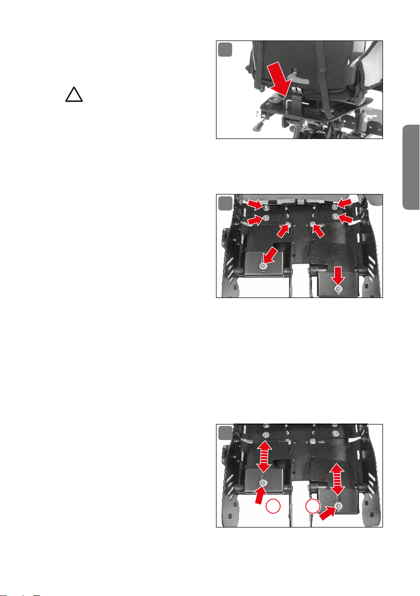
Neupositionierung der Rumpfführungspelotten benötigt man einen
4
zusätzlichen Maulschlüssel SW 10�
Achtung!
1
Der Inbusschlüssel muss immer
bei der MAGICLIGHT mitgeführt
werden, um eventuelle Korrek
turen in der Sitzeinstellung vornehmen oder gelöste Schraubverbindungen sofort
befestigen zu können�
Deutsch
10.3 Sitzschale/Einstellschrauben
Die Sitzschale (Abb� 5) ist aus
5
leichtem Aluminium gefertigt und
lässt sich in Breite und Länge um
jeweils 5 cm individuell einstellen� Um eine genaue Einstellung
durchführen zu können, müssen
zuerst die individuellen Maße am
Patienten abgenommen werden�
Da die Breiteneinstellungen des
Sitzes ohne Polster erfolgen, müssen pro Polster jeweils 2 cm dazu addiert
werden� Um ein ideales Maß an Stabilität zu erhalten, ist es ratsam, zuerst eine
Seite einzustellen und danach die andere Seite�
10.4 Einstellen der Sitzschale
Abnehmen der Sitzauflage, der Seitenpolster und des Abduktionspolsters�
Einstellschrauben mit Inbusschlüssel SW 4 lösen�
10.4.1 Sitztiefe (Oberschenkellänge)
Einstellen der Sitztiefe (Abb� 6):
Nach dem Lösen der Einstell-
6
schrauben (1 / 2) lassen sich
die Bleche für die Beinlängeneinstellung in Längsrichtung
verschieben und auf das in-
1 2
dividuelle Maß des Patienten
einstellen�
BEDI ENUN G / E INSTE L LUN G / MO N TA GE 13
Page 14
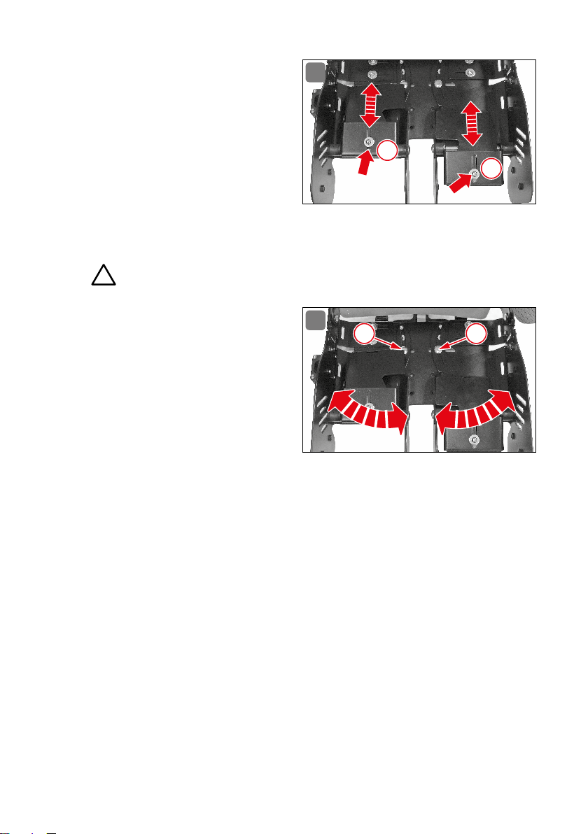
10.4.2 Sitzmulde
Einstellen der Sitzmulde
(Abb� 7):
Schrauben
schlüssel SW 4 lösen�
Die Bleche für die Sitzmuldeneinstellung lassen sich in
Längsrichtung verschieben
und auf das individuelle Maß
des Patienten einstellen�
Schrauben wieder mit Inbusschlüssel SW 4 festdrehen�
Achtung!
2
(1 / 2)
7
mit Inbus-
1
2
10.4.3 Abduktion
Nach dem Lösen der Einstellschrau-
8
3 4
ben der Abduktion (3 / 4) können auch
die Abduktionsführungen (Abb� 8)
variabel eingestellt werden� Sie können die Beine des Patienten parallel oder in einem unterschiedlichen
Winkel führen� Der Winkel für die
Einstellung der Beinschalen deckt
den Bereich von -10° bis + 25° ab�
Besonderheit: Falls der Patient eine einseitige Abduktionseinstellung benötigt,
kann die Führung des zweiten Beines parallel zu der Abduktionseinstellung geführt werden� Dieser Winkelbereich ist einstellbar bis 5°�
10.4.4 Sitzbreite
Einstellen der Sitzbreite (Abb� 9):
Rückenpolster unten öffnen und über dem rotem Klemmhebel nach oben
ziehen�
Schrauben (1 bis 4) am Rückenteil und (5 bis 8) in der Sitzschale mit Inbus-
schlüssel SW 4 lösen�
Sitzbreite auf Maß des Patien ten einstellen, auf korrekte Position der
Rückenlehne achten�
Schrauben (1 bis 4) am Rückenteil und (5 bis 8) in der Sitzschale wie der mit
Inbusschlüssel SW 4 festdrehen�
14 B ED IEN UNG / EIN S TE L LUN G / MO N TA GE
Page 15
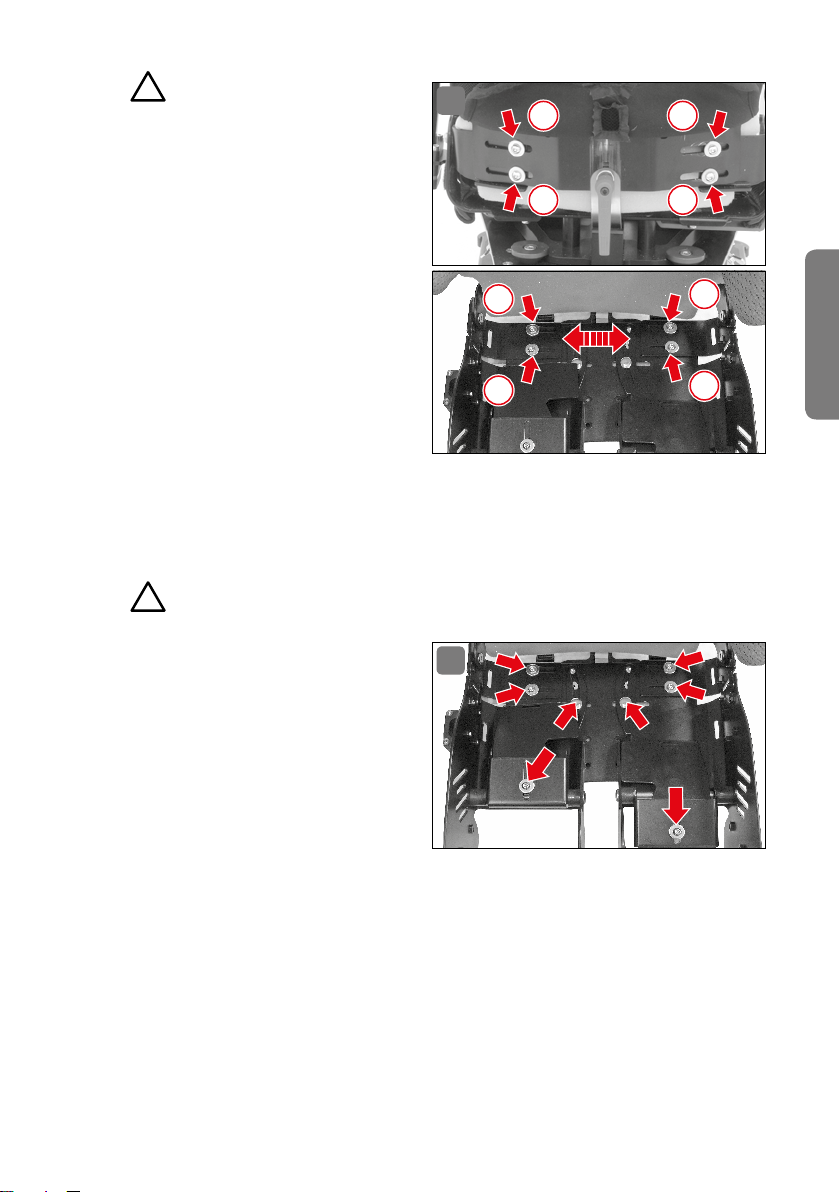
Achtung!
2
Nachdem die Schrauben festgedreht worden sind, muss die korrekte Position noch einmal überprüft werden, um zu gewährleisten,
dass der Patient nicht schief in der
MAGICLIGHT sitzt� Gegebenenfalls
die Einstellung korrigieren�
Rückenpolster wieder über
den roten Klemmhebel ziehen
und unten schließen�
10.4.5 Einstellschrauben festdrehen
Einstellschrauben mit Inbusschlüssel SW 4 festdrehen�
Alle verstellbaren Teile noch einmal auf festen Sitz überprüfen und gebenenfalls die Schrauben nachziehen�
Achtung!
2
9
1
2
7
8
3
4
5
Deutsch
6
Die Einstellschrauben (Abb� 10)
sind wichtigste Befestigungs
punkte bei der MAGIC LIGHT und
müssen regelmäßig auf festen Sitz
überprüft werden� Nur so ist gewährleistet, dass die eingestellten
Maße für den Patienten erhalten
bleiben und er/sie korrekt in der
MAGICLIGHT sitzt�
Abduktionspolster wieder aufstecken�
Seitenpolster wieder aufstecken�
Sitzauflage wieder einlegen
Darauf achten, dass alle Poster faltenfrei montiert sind, damit der Patient keine
Druckstellen bekommen kann� Die Sitzauflage ist so ausgelegt, dass sie bei allen
möglichen Sitzeinstellungen passt� Sie wird mit Klettband auf der Sitzschale
fixiert und kann leicht abgezogen werden�
BEDI ENUN G / E INSTE L LUN G / MO N TA GE 15
10
-
Page 16
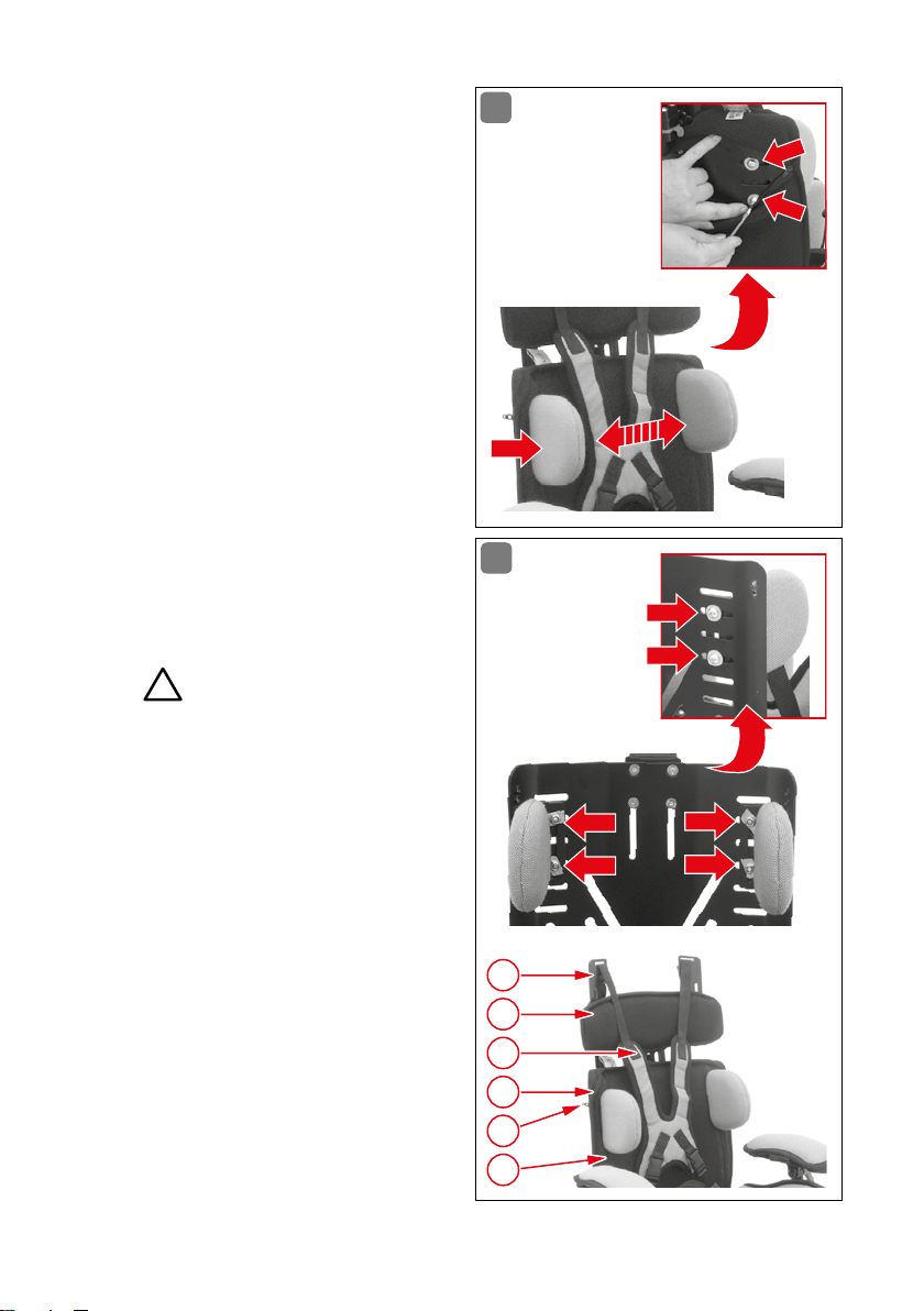
10.5 Rückenlehne/
Rumpfführungspelotten
Die Rumpfführungspelotten (Abb� 11)
lassen sich am besten einstellen,
wenn der Patient im Stuhl sitzt� Um
ein ideales Maß an Halt bieten zu
können, sollte man zuerst eine Seite
einstellen, dann die andere Seite�
Öffnen des Reißverschlusses
des Polsters der unteren Rückenlehne�
2 Schrauben pro Seite mit
Inbussschlüssel SW 4 lösen�
Rumpfführungspelotte auf
Maß des Patienten einstellen�
Schrauben wieder mit Inbussschlüssel SW 4 festdrehen�
Reißverschluss wieder schließen�
Achtung!
2
11
12
Ist die Einstellmöglichkeit der
Rumpfführungspelotte (Abb� 12) in
der Standardposition für den Patienten nicht ausreichend, bietet
die untere Rückenlehne weitere
Montagepositionen� Dazu muss
der Rückenbezug der unteren Rückenlehne komplett abgenommen
werden�
Abnehmen der Kopfstütze
(siehe Abb� 15)
Gurte der Brustschulterpelotte (1) an den Klappschnallen (2) lösen�
Reißverschluss (3) des un-
teren Rückenpolsters öffnen�
16 B EDI ENU NG / E INST E LL UNG / MON TAGE
2
4
1
5
3
5
Page 17

Obere Rückenlehne (4) losschrauben und nach oben herausziehen�
Reißverschlüsse (5) ober-
und unterhalb der Rumpf führungspelotten am Rückenbezug öffnen�
Rückenbezug unten öffnen und nach oben wegziehen�
Schaumstoffpolster entfernen�
Rumpfführungspelotten demontieren (Inbussschlüssel SW 4, Maulschlüssel SW 10)�
Die Rumpfführungspelotten können nun nach den individuellen Maßen des Patienten neu montiert werden�
Schaumstoffpolster wieder einsetzen�
Rückenpolsterbezug wieder überziehen und unten verschließen�
Reißverschlüsse (5) am Rückenbezug ober- und unterhalb der Rumpffüh-
rungspelotten wieder schließen�
Obere Rückenlehne (4) wieder einsetzen, parallel zur unteren Rückenlehne
ausrichten�
Schrauben der oberen Rückenlehne wieder festziehen�
Gurte der Brustschulterpelotte (1) wieder in den Klappschnallen (2) befestigen�
Kopfstütze einsetzen, auf richtige Höhe einstellen (siehe Abb� 15)�
Patient in den Stuhl setzen�
Rumpfführungspelotten einstellen und Schrauben wieder festziehen�
Reißverschluss des Rückenbezugs schließen�
2 3
Achtung!
10.6 Rückenlehne/Rückenhöhe
Die Rückenlehne (Abb� 13) besteht aus zwei Teilen, einem unteren festen Teil, der
über Drehpunkte mit der Sitzschale verbunden ist und dem oberen beweglichen
und verstellbaren Teil� Die Rückenhöhe kann so um 5 cm verlängert werden�
Nur der obere Teil wird an die Größe des Patienten angepasst� Dieser Aufbau hat
den Vorteil, dass bei einer Verstellung der Rückenhöhe die Gur tführungslaschen
und die Gurte automatisch mit angepasst werden�
Deutsch
Einstellung der Rückenlehne:
Herausnehmen der Kopfstütze (siehe Abb� 15)
Öffnen des hinteren Reißverschlusses der unteren Rückenlehne�
Lösen der beiden Schrauben mit Inbussschlüssel SW 4�
BEDI ENUN G / E INSTE L LUN G / MO N TA GE 17
Page 18
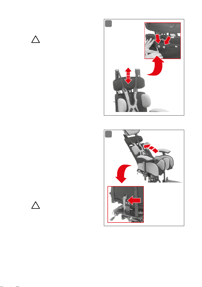
Rückenhöhe auf Maß des
Patienten einstellen�
Achtung!
2
Die obere Rückenlehne muss parallel zur unteren Rückenlehne eingestellt sein, um eine genaue Gur tführung gewährleisten zu können�
Schrauben wieder mit Inbussschlüssel SW 4 festziehen�
Reißverschluss wieder schließen�
Kopfstütze wieder einsetzen
und auf richtige Höhe einstel
-
len (siehe Abb� 15)�
13
10.7 Rückenlehne/Neigung
14
Die Neigung der Rückenlehne
(Abb� 14) lässt sich an die Bedürfnisse des Patienten anpassen� Sie
ist in einem Winkel von -10° bis +30°
fest einstellbar�
Roter Klemmhebel an der unteren
Rückenlehne mit 2 Umdrehungen
lösen, die richtige Neigung einstellen, Klemmhebel wieder festdrehen�
Achtung!
4
Soll die Rückenlehne beweglich
sein, so lässt sich diese Möglichkeit
über die Rückendynamik einstellen
(siehe Abb� 21)�
10.8 Rückenlehne/Kopfstütze
Die Kopfstütze (Abb� 15) lässt sich durch die Raststange und die beiden Gelenke
individuell auf den Kopf des Patienten einstellen� Durch Drücken des Rast-
18 B ED IENU NG / EINS T EL LUN G / MON TAG E
Page 19
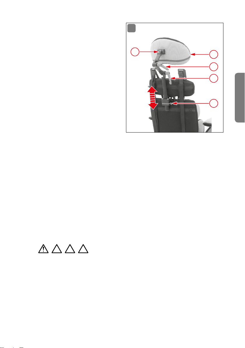
knopfes (4) an der Halterung der
Kopfstütze (1) lässt sie sich einfach
und sicher in der Höhe verstellen�
Zieht man leicht an der Stange der
Kopfstütze und drückt kurz den
Rastknopf, rastet die Stange in der
nächsten Position ein� Drückt man
den Rastknopf permanent, kann
man die Kopfstütze komplett de
montieren�
15
5
1
2
3
-
Zur weiteren Einstellung der Kopfstütze sind die beiden Gelenke vorgesehen� Sie ermöglichen eine perfekte Lage am Kopf des Patienten�
Durch Lösen der beiden Klemmhebel (2 + 3) um jeweils 2 Umdrehungen können die Gelenke individuell eingestellt
werden� Anschließend die beiden Klemmhebel wieder festdrehen�
Muss die Kopfstütze zusätzlich in ihrer Neigung verändert werden, öffnet man
die einzelne Halteschraube (5) mit dem Inbussschlüssel SW 4 und stellt dann
die Neigung ein�
Zum Waschen des Kopfstützenbezugs muss das oberste Gelenk komplett von
der Haltestange demontiert werden (Inbussschlüssel SW 4), dann den Reißverschluss öffen und den Kopfstützenbezug über die Haltestange abziehen� Nach
dem Waschen den Kopfstützenbezug wieder über die Haltestange auf das Kopfstützenpolster ziehen, den Reißverschluss schließen und die Kopfstütze wieder
mit der Haltestange verschrauben (Inbussschlüssel SW 4)�
2 3 4
10.9 Becken-Sicherheitsgurt
Standardmäßig ist bei der MAGIC LIGHT ein 4-Punkt Becken-Sicherheitsgurt
(Abb� 16) mit Neopren-Polster (1) montiert, der für Jungen und Mädchen verwend
bar ist� Nachdem der Becken-Sicherheitsgurt an dem Patienten angepasst ist,
wird der Gurt mit der Verschlussschnalle geschlossen und mit der in dem Gurt
eingefassten Öse mit einer Hand zugezogen� So hat der Bediener die Möglichkeit,
den Patienten mit der anderen Hand zu stützen�
Achtung!
4
-
Deutsch
BEDI ENUN G / E INSTE L LUN G / MO N TA GE 19
Page 20
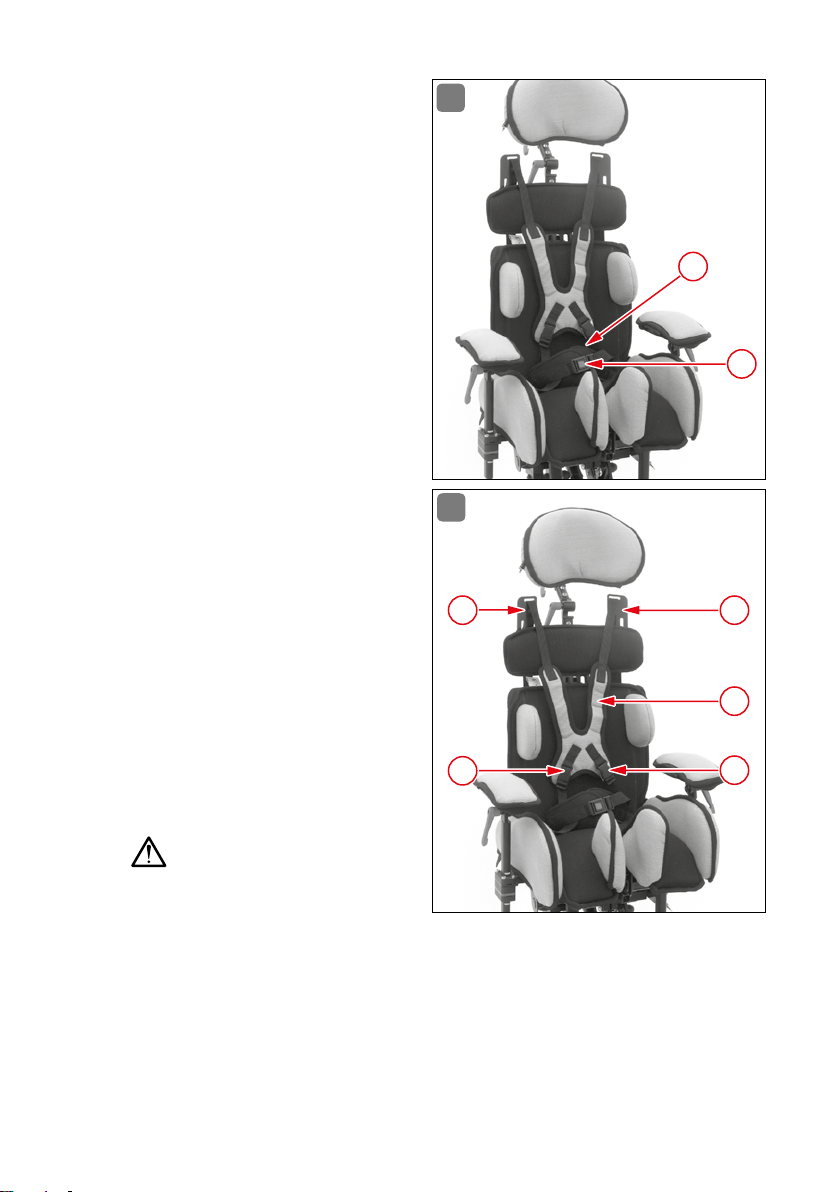
Durch Drücken des roten Knopfes
(2) auf der Verschlussschnalle lässt
sich der Becken-Sicherheitsgurt
öffnen�
10.10 Rückenlehne/
Brustschulterpelotte
Standardmäßig ist bei der MAGICLIGHT eine Brustschulterpelotte
(1) (Abb� 17) in Stoff-Ausführung
montiert, die entweder für Jungen
oder Mädchen vorgesehen ist� Um
den Patienten in den Sitz setzen zu
können, die unteren Clips (2) sowie
die unteren Klappschnallen (3) an
den Gurtführungsblechen lösen�
16
1
2
Brustschulterpelotte (1) nach
hinten schlagen und Patient in
den Sitz setzen�
Brustschulterpelotte (1) von
hinten über den Kopf des Patienten ziehen und Gurt an den
Clips (2) befestigen�
Untere Gurte leicht spannen
und mit den Klappschnallen
(3) sichern�
Obere Gurtführung kontrollieren�
Achtung!
Darauf achten, dass die Gurte den
Patienten nicht am Hals drücken
und die Gefahr einer Strangulation entstehen kann�
Obere Gurte spannen und Patient fixieren�
Sollte der obere Gurtverlauf nicht optimal sein, müssen die Gurtführungsbleche
neu eingestellt werden (siehe Abb� 18)�
17
3
3
1
2
2
20 BEDI ENUN G / E INSTE L LUN G / MO N TA GE
Page 21
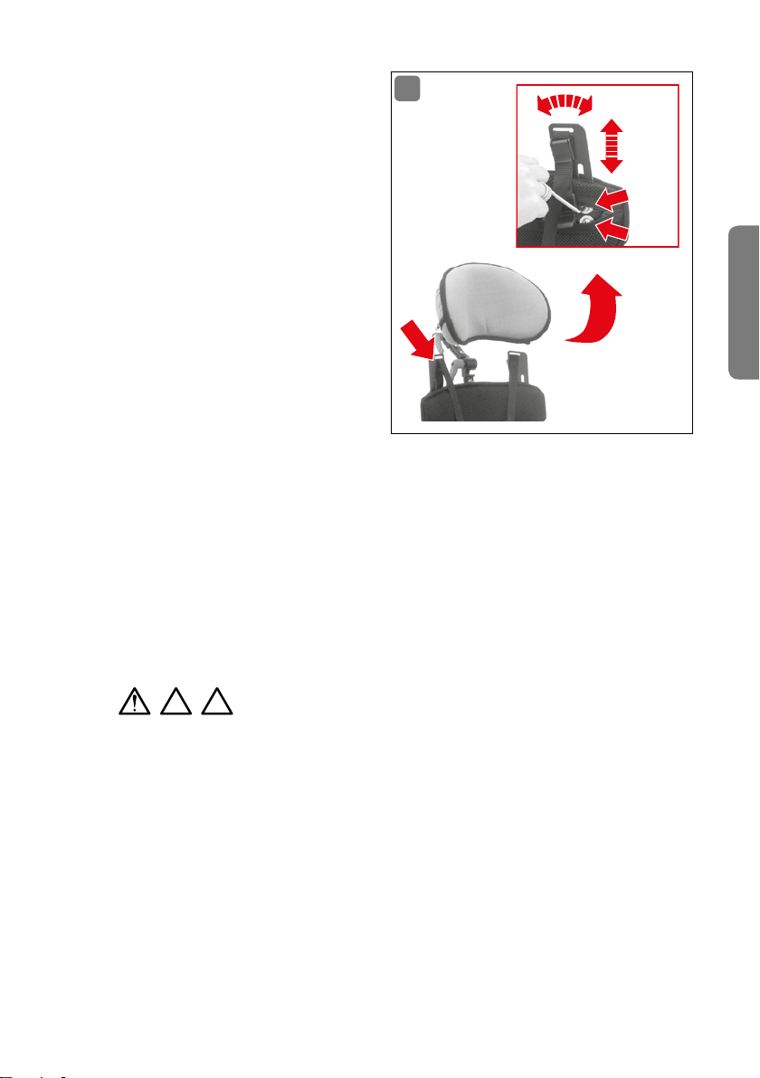
10.11 Rückenlehne/Gurtführung
Um den Gurtverlauf der Brustschulterpelotte für jeden Patienten
optimal einstellen zu können, verfügt die MAGICLIGHT über Gurtführungsbleche (Abb� 18) die eine
individuelle Einstellung der Gurtführung ermöglichen� Die Gurtführungsbleche sind am oberen Rückenteil montiert, um bei Veränderung der Rückenhöhe automatisch
die gleiche Voreinstellung der Gurtführung zu garantieren� Der Verlauf
der Gurte der Brustschulterpelotte
soll mittig über dem Schlüsselbein
ausgerichtet sein�
Gurtführungen einstellen:
Reißverschluss am Polster des oberen Rückenteils öffnen�
Je 2 Schrauben pro Seite mit Inbussschlüssel SW 4 lösen�
Gurtführungsbleche auf optimale Gurtführung der Brustschulterpelotte
einstellen�
Schrauben mit Inbussschlüssel SW 4 wieder festziehen�
Gurtführung am Patienten überprüfen�
Gegebenenfalls Einstellung ändern�
Reißverschluss am Polster des oberen Rückenteil schließen�
18
Deutsch
2 3
Achtung!
Falsch:
Gurtverlauf zu nah am Hals - Strangulationsgefahr�
Gurtverlauf zu weit auf den Schultern - die Gurte können über die Schultern des Patienten abrutschen; der Patient ist dann nicht mehr fixiert und
kann gegebenenfalls aus dem Stuhl fallen und sich verletzen�
10.12 Armauflagen
Die Armauflagen (Abb� 19) sind individuell und variabel für den Patienten einstellbar� Die Höhe der Armauflagen (3) wird über die Rastverstellung eingestellt� Dazu
den Hebel (1) drücken und Armlehne auf gewünschte Höhe stellen�
BEDI ENUN G / E INSTE L LUN G / MO N TA GE 21
Page 22
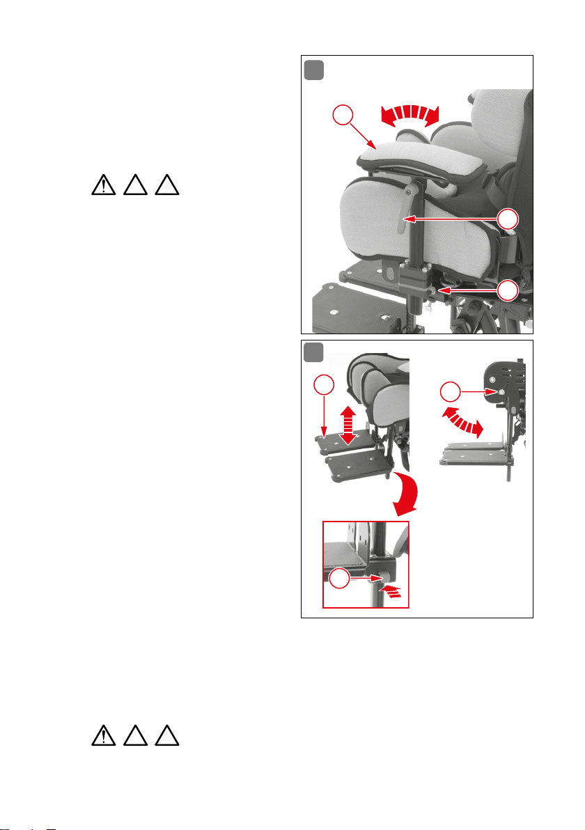
Die Neigung der Armauflage wird
per Klemmhebel (2) eingestellt� Den
Klemmhebel mit 2 Umdrehungen
lösen, die Neigung der Armauflage
einstellen und den Klemmhebel (2)
wieder festdrehen�
19
3
3 4
10.13 Fußbretter
Die Fußbretter (Abb� 20) sind bei
der MAGICLIGHT an den Abduktionsführungen montiert� Sie sind
schwingend gelagert, um bei Bedarf dem Patienten eine größtmögliche Bewegungsfreiheit zu bieten�
Eine Klemmschraube (3) seitlich an
der Sitzschale dient zur möglichen
Feststellung der Fußbretter� Die
Fußbretter lassen sich senkrecht
oder in einem individuellen Winkel fixieren�
per Rasterung in der Höhe verstellt�
Sie lassen sich einzeln auf die jeweilige Höhe bringen, die dem Maß
des Patienten entspricht� Durch die
Rasterung ist garantiert, dass die
Fußbretter auch auf eine gleiche
Höhe eingestellt werden können�
Ein umständliches Ausmessen
entfällt�
Die Fußbretter werden
Achtung!
20
2
1
2
3
1
Ein kurzes Drücken des Rastknopfs
(1) und das Fußbrett (2) rastet in der nächsten Position ein; durch Halten des
Rastknopfs (1) lässt sich das Fußbrett (2) nach unten demontieren� Durch um-
fangreiches Zubehör, wie zum Beispiel Fußfixierungen oder Polsterungen, lassen
sich die Fußbretter individuell ausstatten�
3 4
22 B EDI ENUN G / E INSTE L LUN G / MO N TA GE
Achtung!
Page 23
11. Täglicher Gebrauch
11.1 Rückendynamik
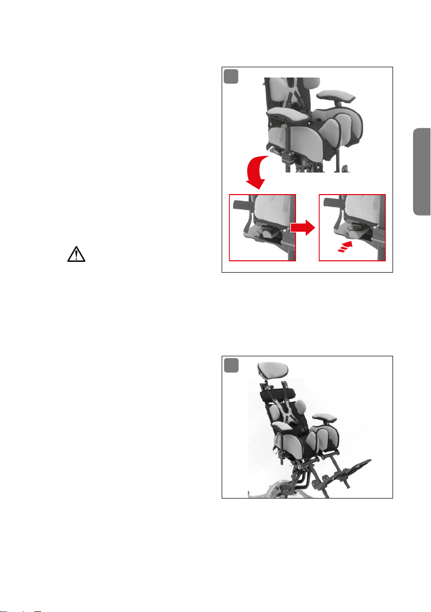
Die Sitz-Rückeneinheit (Abb� 21)
von MAGIC LIGHT ist über Dreh
punkte miteinander verbunden�
Die Rückenlehne ist beweglich
und kann so die plötzlich aufkommende Energie beim Strecken des
Patienten über eine Druckfeder gut
absorbieren� Nach der Streckung
wird der Patient wieder in die ursprüngliche Position zurückgebracht� In der Standardeinstellung
ist die Rückendynamik deaktiviert�
Achtung!
Roter Hebel in Standardposition
Rückendynamik ist deaktiviert und die Rückenlehne steht fest
Roter Hebel eingeschoben
Rückendynamik ist aktiviert und die Rückenlehne ist beweglich
11.2 Liegeposition
Der Winkel der Rückenlehne
(Abb� 22) lässt sich bis zu 30° neigen, um eine entspannte Liegeposition bieten zu können� Dazu
den roten Klemmhebel an der unteren Rückenlehne lösen, die gewünschte Neigung einstellen und
den Klemmhebel wieder festdrehen (siehe Abb� 14)� Zur weiteren
Unterstützung der Liegeposition
lassen sich die Fußbretter eben
falls verstellen, um dem Patienten eine größtmögliche Bequemlichkeit zu bieten
(siehe Abb� 20)�
21
-
22
-
Deutsch
TÄGLICHER GEBRAUCH 23
Page 24
12. Optionales Zubehör
12.1 Oberarmbegrenzungen
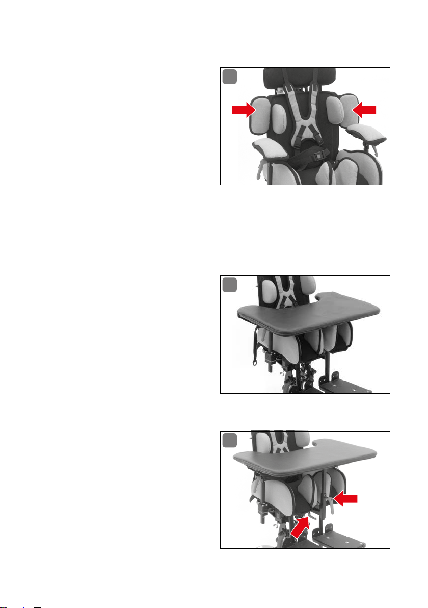
Die Oberarmbegrenzungen (Abb� 23)
dienen zur Einschränkung der Bewegungsfreiheit�
dadurch seine Arme nicht mehr
nach hinten, zwischen Rücken
lehne und Armauflagen, bewegen�
Die Oberarmbegrenzungen werden
standardmäßig an der Rückenlehne montiert� Rückenlehne und
Rückenpolster sind für die nachträgliche Montage der Oberarmbegrenzungen
vorbereitet� Die Polster der Oberarmbegrenzung sind abnehmbar und können
gewaschen werden�
Lieferung im Set, inkl� Montageanleitung und Befestigungsmaterial�
12.2 Therapietisch, klettbar
Die einfache Version des Therapietisches (Abb� 24) wird auf die Armauflagen aufgelegt, an den Patienten
angepasst und mit vorhandenen
Klettgurten auf den Armauflagenpolstern befestigt� Zusätzlich wird
der Therapietisch mit einem Haltegurt an der Rückenlehne fixiert�
Der Patient kann
23
-
24
Lieferung inkl� Montageanleitung�
12.3 Therapietisch, aufsteckbar
Die verstärkte Version des Therapietisches (Abb� 25) wird an der
Sitzschale montiert� Dazu wird ein
separater Halter gemäß beiliegenderMontageanleitung an die Unterseite der Sitzschale geschraubt�
Nachdem der Therapietisch auf
den Halter aufgesteckt worden
ist, lässt er sich in der Höhe und
24 OPTIONALES ZUBEHÖR
25
Page 25
im Abstand verschieben und so individuell an den Bedürfnissen des Patienten
anpassen�
Lieferung inkl� Montageanleitung�
12.4 Kopfstütze, Standard
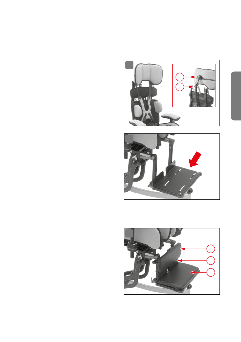
Zur Anpassung der Kopfstütze
(Abb� 26) an den Patienten ist diese
mit einem Klemmhebel (1) ausge-
stattet� Die Haltestange verfügt
über eine Rasterung für die Höhenverstellung; die Neigung der Kopfstütze lässt sich über ein Gelenk mit
Feststellschraube (2) verändern�
12.5 Fußbank
Fußbanksystem ALULINE (Abb� 27)
mit Kniewinkel Rasterverstellung
in durchgehender Ausführung,
schwarz beschichtet, inklusive
Stoßecken und Fußbankfolie� Zur
Montage am Untergestell prüfen
Sie bitte, ob das verwendete Un
tergestell für die Aufnahme von
ALULINE vorgesehen ist�
Lieferung inkl� Montageanleitung�
26
2
1
Deutsch
27
-
12.6 Fußbankpolsterung
Zur weiteren Ausstattung von ALULINE (Abb� 28) können folgende
Polsterungen montiert werden:
Fußbankpolster (1)
Fersenkantenpolster (2)
Wadenplatte (3)
OPTIONALES ZUBEHÖR 25
28
3
2
1
Page 26
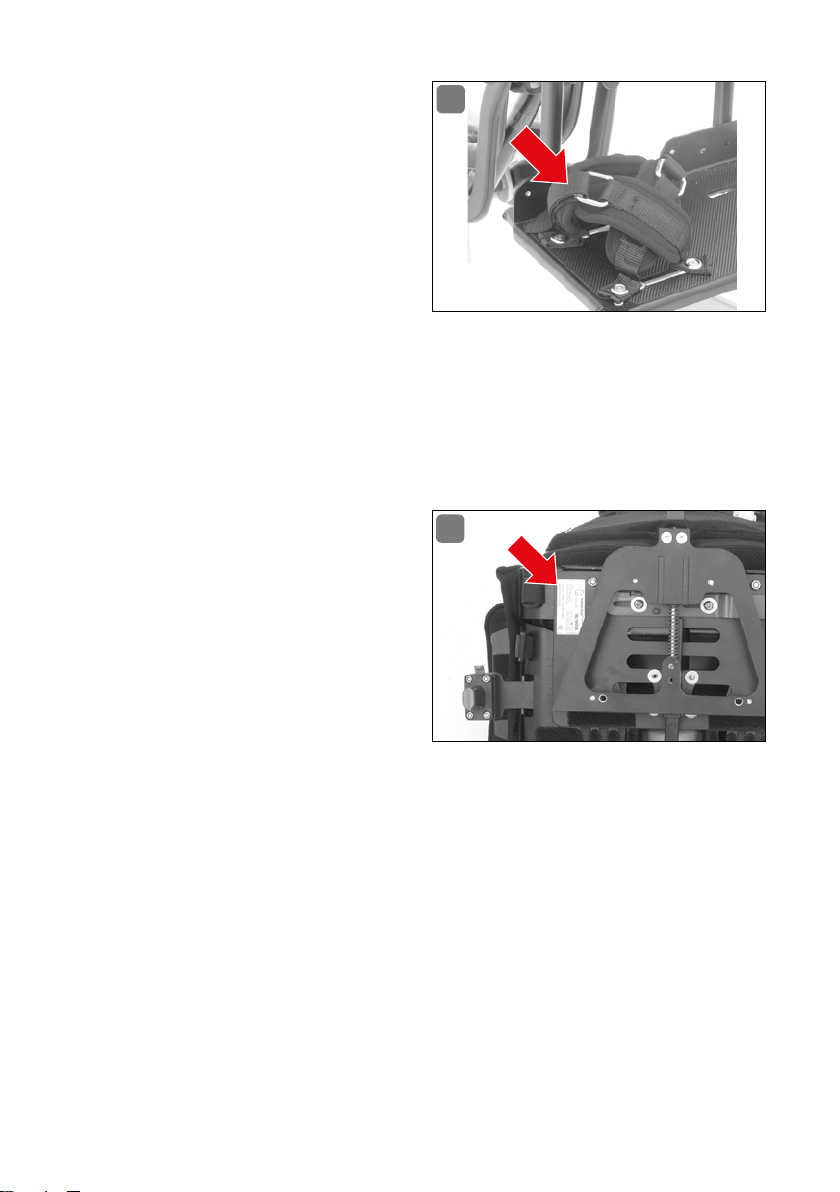
12.7 Fußfixierungen
Für die Fußbretter oder die Fußbank ALULINE (Abb� 29) können
folgende Fußfixierungen von in
terco benutzt werden�
Fußriemen mit Ristpolster aus
Klett/Flausch
Fußriemen mit Umlenkrolle
und Ristpolster
Fußgamaschen in NeoprenAusführung
Fußgamaschen mit Vorfußfixierung in Neopren-Ausführung
Gezeigt ist die Version „Fußgamaschen mit Vorfußfixierung in Neopren-Ausführung“� Lieferung im Set, inkl� Montageanleitung�
29
-
13. Typenschild
Das Typenschild (Abb� 30) ist an
der Unterseite der Sitzschale angebracht� Dort können Sie die Seriennummer und die Bau-Größe der
MAGICLIGHT ablesen�
Diese Informationen bei eventuellen Ersatzteilbestellungen oder
benötigtem Zubehör bitte immer angeben !
30
26 TYPENSCHILD
Page 27

14. Wartung / Kontrolle
Zum Wohl des Patienten ist eine regelmäßige Wartung und Kontrolle des Sitzsystems unverzichtbar� Bitte überprüfen Sie MAGICLIGHT regelmäßig auf Verschleiß oder defekte Teile�
Vor jedem Gebrauch:
Überprüfung aller Polster auf richtigen Sitz und Beschädigung�
Überprüfung der Gurte von Brustschulterpelotte und Beckengurt auf Verschleiß und festen Halt�
Achtung: Verschlissene Gurte müssen sofort ausgetauscht werden�
Überprüfung aller beweglichen Teile auf festen Sitz�
Überprüfung der Sitzeinstellungen am Patienten�
Achtung: Einstellungen gegebenenfalls neu anpassen�
Alle 4 Wochen (je nach Gebrauchshäufigkeit auch öfter):
Überprüfung des Sitzgestells auf Beschädigungen�
Überprüfung Druckfeder der Rückendynamik�
Achtung: Bei Bruch der Druckfeder sofort austauschen lassen�
Überprüfung Federblech der Rückenlehnenverstellung�
Achtung: Bei Bruch des Federblechs sofort austauschen lassen�
Überprüfung sämtlicher Schraubverbindungen und Klemmhebel�
Achtung: Beschädigte Klemmhebel sofort austauschen lassen�
Deutsch
Alle 6 Monate (je nach Gebrauchshäufigkeit auch öfter):
Komplette Überprüfung von MAGICLIGHT im Sanitätshaus oder beim Fachhändler�
WARTUNG / KONTROLLE 27
Page 28

15. Serviceplan
Pos. Bereich Prüfung
1 Sitzschale
2 Schraubver-
bindungen
3 Optik
Wartung wurde durchgeführt von
Einstellung /
Funktion
Rückenverstellung
Rückendynamik
Kopfstütze
Armlehnen
Fußbretter
Trapezadapter
Schrauben
angezogen
Roststellen
Lack
Stoffnähte
(Lage/Aussehen)
Typenschild
Sauberkeit
in Ordnung Beschädigungen /
Verformungen
Austausch/
Ersatz
Ort/Datum Unterschrift Nächster Service
Wartung wurde durchgeführt von
Ort/Datum Unterschrift Nächster Service
Achtung!
Reparaturen, Einstellungen, Anbau- und Instandhaltungsmaßnahmen dürfen nur
von autorisierten Partnern (Sanitätshäuser oder Fachhändler) oder bei interco
GmbH durchgeführt werden�
Einen Partner in Ihrer Nähe erfragen Sie bitte telefonisch bei unserem Kundenservice unter Tel�: +49 (0) 22 43 / 88 07-0
28 SERVICEPLAN
Page 29

16. Material / Reinigung / Pflege
Die Abduktion-, Seiten-, Sitz- und Rückenpolster werden aus Kaltschaum HE40
in 20 bzw� 30 mm Stärke hergestellt� Die Polster für die Rumpfführungspelotten
sind aus Verbundschaum RG140 in 10 mm Stärke�
Die Bezüge werden aus hochwertigem Abstandsgewirke gefertigt� Sie können das
Aussehen der wertvollen Bezüge Ihres Sitzsystems selbst beeinflussen, indem Sie
regelmäßig reinigen; staubsaugen oder vorsichtig bürsten, bevor sich
Schmutz festsetzt�
verschüttete Flüssigkeiten sofort mit saugfähigem Material aufnehmen –
je länger Sie damit warten, desto schwieriger wird die Reinigung!
Sollte doch einmal eine verschüttete Flüssigkeit eingetrocknet sein, hilft
meist eine milde Feinwaschmittellösung, gering dosiert auf ein Tuch geben
und damit abtupfen (niemals kräftig reiben)�
Wichtig dabei: Niemals diese Lösung direkt auf den Bezug geben, sondern immer nur auf das Tuch� Gegebenenfalls mit klarem Wasser leicht abreiben� Bitte
beachten Sie: Der Stoff darf nicht gechlort oder gebleicht werden� Das Gewebe
sollte möglichst wenig direktem Sonnenlicht ausgesetzt werden� Alle unsere
Bezugsstoffe sind bei 30° C waschbar� Benutzen Sie zur Wäsche ein Feinwaschmittel oder eine schonende chemische Reinigung� Trocknen Sie den Bezug nicht
im Trockner! Bügeln bei niedriger Temperatur� Sollten Sie den Bezug der Sitzschale häufiger waschen wollen, empfiehlt sich ein zweiter Bezug, den Sie dann
im Wechsel aufziehen können� Fragen Sie hier zu in Ihrem Sanitätshaus nach� Die
Zusatzteile reinigen Sie bitte mit einer haushaltsüblichen milden Seifenlauge�
Der Grundkorpus des Sitzsystems ist mit einer hochwertigen, widerstandsfähigen Kunststoffbeschichtung versehen� Reinigen Sie diesen mit Seifenlauge und
einem weichen Schwamm� Vermeiden Sie aggressive oder scheuernde Mittel, da
dadurch die Oberfläche der Kunststoffbeschichtung beschädigt werden kann�
Deutsch
Desinfektion
Zur Desinfektion verwenden Sie bitte Mittel, die auf Wasserbasis hergestellt
sind, wie z� B� Terralin, Quartamon Med oder Sagrotan Original Konzentrat� Bitte
beachten Sie dabei die vom Hersteller vorgegebenen Anwendungshinweise�
Kunststoffteile pflegen Sie am besten mit einem handelsüblichen Kunststoffreiniger (beachten Sie bitte die Produktinformationen des Reinigungsmittels)�
Sollte die Lackierung durch Kratzer beschädigt sein, können Sie die fehlerhafte
Stelle mit einem Lackstift ausbessern�
M AT ERI A L / REIN IGU NG / PFLEG E 29
Page 30

17. Konformitätserklärung
EG-Konformitätserklärung für Medizinprodukte
Name des Herstellers: interco GmbH
Gesellschaft zur Planung und Vertrieb von
Rehabilitationshilfen mbH
Adresse des Herstellers: Im Auel 50
53783 Eitorf
Wir erklären hiermit, dass das Produkt
Artikelbezeichnung: MAGICLIGHT Gr� 0-3 (Art� Nr�: 37100-37103)
Ausführung:
Commission: Serienfertigung
den einschlägigen Bestimmungen der nachstehenden Richtlinie entspricht:
Richtlinie 93/42/EWG über Medizinprodukte, Anhang I und VII
Eitorf, den 06� Oktober 2008
modulares, mitwachsendes Sitzsystem, Maße
gemäß Tabelle, Ausstattung gemäß Definition
Michael Markwald
Geschäftsführer
30 KONFORMITÄTSERKLÄRUNG
Page 31

18. Garantie
In Ergänzung zu den allgemeinen Geschäftsbedingungen gewähren wir auf das von
uns gelieferte Produkt eine Garantie von einem Jahr� Die Garantiezeit beginnt am
Tag des Kaufs� Zum Nachweis bewahren Sie bitte den Kaufbeleg für die Dauer der
Garantiezeit auf� Nach Einsendung der Garantiekarte gewähren wir Ihnen zusätzlich ein weiteres Jahr Herstellergarantie, so besteht dann eine Garantiezeit von
insgesamt zwei Jahren� Unbrauchbare oder schadhafte Teile werden innerhalb der
Gewährleistungsfrist repariert oder unentgeltlich ersetzt� Ausgeschlossen hiervon
sind entwicklungsbedingte Änderungen sowie Verschleißteile (Polster und Bezüge)�
Achtung!
Für Schäden aufgrund von Kombinationen unseres Produktes mit Fremdprodukten jeglicher Art, die unter Umständen erhebliche Gefahren in sich bergen,
können wir keine Haftung übernehmen� Ausgenommen hiervon sind nur ausdrücklich von unserem Hause freigegebene Produkte anderer Hersteller� Weiter
ausgeschlossen sind Mängel, die aufgrund natürlichen Verschleißes, übermäßiger Beanspruchung, gewaltsamer und vorsätzlicher Beschädigung sowie nicht
bestimmungsgemäßer Verwendung auftreten�
Nichtbeachtung der Bedienungsanleitung sowie unsachgemäß durchgeführte
Wartungs- oder Reparaturarbeiten als auch insbesondere technische Änderungen
und Ergänzungen (Anbauten) ohne Zustimmung der Fa� interco GmbH führen zum
Erlöschen sowohl der Garantie als auch der Produkthaftung allgemein�
Deutsch
Technische Änderungen bleiben vorbehalten�
GARANTIE 31
Page 32

19. Wiedereinsatz
MAGICLIGHT® ist für einen Wiedereinsatz geeignet� Bevor
müssen alle notwendigen Reinigungs- und Wartungsarbeiten durchgeführt werden� Bei einer Weitergabe ist unbedingt darauf zu achten, alle für den Gebrauch
notwendigen Unterlagen (also auch diese Gebrauchsanweisung) mitzugeben�
sie
weitergegeben wird,
20. Entsorgung
Bitte beachten Sie bei der Entsorgung des Verpackungsmaterials oder von beschädigten Teilen die jeweiligen Entsorgungsbestimmungen Ihres Landes�
Verpackung
Karton: Altpapiersammlung oder Papiercontainer
Styropor und Folie: Gelbe Tonne oder Gelber Sack
Einzelteile
Bezüge oder Polster: Restmüll
Kunststoffteile: Entsprechend der Kennzeichnung in die dafür
vorgesehenen Container / Tonnen
Metallteile: Container für Metalle
Ausgemusterte Sitzsysteme können auch bei den Sanitätshäusern oder Fachhändlern zurückgegeben werden�
32 WIEDEREINSATZ
Page 33

Notizen
GARANTIEKARTE
Deutsch
Bei Einsendung dieser Karte gewähren wir auf Ihre MAGICLIGHT® eine erweiterte
Garantie von insgesamt 2 Jahren. Bitte füllen Sie diese Garantiekarte sorgfältig und
vollständig aus und senden Sie diese an uns zurück – vielen Dank.
Kostenträger/Krankenkasse:
Ort des Kostenträgers:
Seriennummer:
Lieferdatum:
Name des Patienten:
Straße:
PLZ/Ort:
Telefon*:
E-Mail*:
* freiwillige Angaben
Page 34

Notizen
ANTWORTKARTE
ABSENDER
Name
Straße
PLZ/Ort
Bitte
ausreichend
frankieren !
ANTWORT
interco GmbH
Im Auel 50
53783 Eitorf - Germany
Page 35

Contents
1. Introduction � � � � � � � � � � � � � � � � � � � � � � � � � � � � � � � � � � � � � � � � � � � � � � � � � � � � 37
2. Medical requirements / indication � � � � � � � � � � � � � � � � � � � � � � � � � � � � � � � � � 37
3. General � � � � � � � � � � � � � � � � � � � � � � � � � � � � � � � � � � � � � � � � � � � � � � � � � � � � � � 38
4. Modules overview � � � � � � � � � � � � � � � � � � � � � � � � � � � � � � � � � � � � � � � � � � � � � 39
5. Combination options � � � � � � � � � � � � � � � � � � � � � � � � � � � � � � � � � � � � � � � � � � � 40
6. Technical data � � � � � � � � � � � � � � � � � � � � � � � � � � � � � � � � � � � � � � � � � � � � � � � � � 40
7. Safety instructions � � � � � � � � � � � � � � � � � � � � � � � � � � � � � � � � � � � � � � � � � � � � � � 41
8. Caution symbols � � � � � � � � � � � � � � � � � � � � � � � � � � � � � � � � � � � � � � � � � � � � � � � 42
9. Quickguide � � � � � � � � � � � � � � � � � � � � � � � � � � � � � � � � � � � � � � � � � � � � � � � � � � � � 43
10. Operation / adjustment / assembly � � � � � � � � � � � � � � � � � � � � � � � � � � � � � � � � 44
10�1 Trapezoidal adapter � � � � � � � � � � � � � � � � � � � � � � � � � � � � � � � � � � � � � � � � � � � � 44
10�2 Tool � � � � � � � � � � � � � � � � � � � � � � � � � � � � � � � � � � � � � � � � � � � � � � � � � � � � � � � � � � 44
10�3 Seat shell/adjusting screws � � � � � � � � � � � � � � � � � � � � � � � � � � � � � � � � � � � � � 45
10�4 Adjusting the seat shell � � � � � � � � � � � � � � � � � � � � � � � � � � � � � � � � � � � � � � � � � 45
10�5 Back rest/Lateral side supports � � � � � � � � � � � � � � � � � � � � � � � � � � � � � � � � � � 48
10�6 Back rest/Back height � � � � � � � � � � � � � � � � � � � � � � � � � � � � � � � � � � � � � � � � � � � 49
10�7 Back rest/Inclination angle � � � � � � � � � � � � � � � � � � � � � � � � � � � � � � � � � � � � � � 50
10�8 Back rest/Head rest � � � � � � � � � � � � � � � � � � � � � � � � � � � � � � � � � � � � � � � � � � � � 50
10�9 Hip belt � � � � � � � � � � � � � � � � � � � � � � � � � � � � � � � � � � � � � � � � � � � � � � � � � � � � � � � � 51
10�10 Back rest/Chest harness � � � � � � � � � � � � � � � � � � � � � � � � � � � � � � � � � � � � � � � � 52
10�11 Back rest/Strap arrangement � � � � � � � � � � � � � � � � � � � � � � � � � � � � � � � � � � � � 52
10�12 Arm rests � � � � � � � � � � � � � � � � � � � � � � � � � � � � � � � � � � � � � � � � � � � � � � � � � � � � � 53
10�13 Foot rests � � � � � � � � � � � � � � � � � � � � � � � � � � � � � � � � � � � � � � � � � � � � � � � � � � � � � 54
11. Daily use � � � � � � � � � � � � � � � � � � � � � � � � � � � � � � � � � � � � � � � � � � � � � � � � � � � � � 54
11�1 Dynamic back rest � � � � � � � � � � � � � � � � � � � � � � � � � � � � � � � � � � � � � � � � � � � � � 54
11�2 Supine position � � � � � � � � � � � � � � � � � � � � � � � � � � � � � � � � � � � � � � � � � � � � � � � � 55
12. Optional accessories � � � � � � � � � � � � � � � � � � � � � � � � � � � � � � � � � � � � � � � � � � � 55
12�1 Upper arm supports � � � � � � � � � � � � � � � � � � � � � � � � � � � � � � � � � � � � � � � � � � � � 55
12�2 Therapy tray table with Velcro attachment � � � � � � � � � � � � � � � � � � � � � � � � � 56
12�3 Therapy tray table, attachable � � � � � � � � � � � � � � � � � � � � � � � � � � � � � � � � � � � � 56
12�4 Head rest, standard � � � � � � � � � � � � � � � � � � � � � � � � � � � � � � � � � � � � � � � � � � � � 56
12�5 Leg rest � � � � � � � � � � � � � � � � � � � � � � � � � � � � � � � � � � � � � � � � � � � � � � � � � � � � � � 57
12�6 Leg rest cushions � � � � � � � � � � � � � � � � � � � � � � � � � � � � � � � � � � � � � � � � � � � � � � 57
12�7 Foot restraints� � � � � � � � � � � � � � � � � � � � � � � � � � � � � � � � � � � � � � � � � � � � � � � � � 57
13. Rating plate � � � � � � � � � � � � � � � � � � � � � � � � � � � � � � � � � � � � � � � � � � � � � � � � � � � 58
14. Maintenance / inspection � � � � � � � � � � � � � � � � � � � � � � � � � � � � � � � � � � � � � � � 58
15. Service plan � � � � � � � � � � � � � � � � � � � � � � � � � � � � � � � � � � � � � � � � � � � � � � � � � � � 59
16. Materials / cleaning / care � � � � � � � � � � � � � � � � � � � � � � � � � � � � � � � � � � � � � � � 60
English
35
Page 36

17. Declaration of conformity � � � � � � � � � � � � � � � � � � � � � � � � � � � � � � � � � � � � � � � � 61
18. Warranty � � � � � � � � � � � � � � � � � � � � � � � � � � � � � � � � � � � � � � � � � � � � � � � � � � � � � � 62
19. Reuse � � � � � � � � � � � � � � � � � � � � � � � � � � � � � � � � � � � � � � � � � � � � � � � � � � � � � � � � 63
20. Disposal � � � � � � � � � � � � � � � � � � � � � � � � � � � � � � � � � � � � � � � � � � � � � � � � � � � � � � 63
36
Page 37

1. Introduction
Thank you very much for choosing a quality product from interCo! We hope you
enjoy using our product and wish you great therapeutic success� Please do not
hesitate to contact us should you have any questions�
The product has been tested within a temperature range of -20° C to +60° C
(-4° F to +140° F)� It is not always possible to avoid differences in color between
individual production runs� We will be unable to accept any complaints or claims
related to such differences� Please understand that improper treatment, stains
or color differences in the fabrics, as described above, do not represent grounds
for any claims or complaints�
Please note that damage, failures or injuries can only be avoided through precise
handling in accordance with these operating guidelines� Familiarize yourself
with the handling and function of the product and practice appropriate handling
procedures prior to initial use�
Keep these operating guidelines for later use�
Please make a note of the order number, which is located on the back of these
operating guidelines, and keep the number in a safe place� If you should lose these
operating guidelines, you will then be able to request a new copy without any difficulty using this number� This ensures the prevention of defects and damage, as
well as injury to the patient, during adjustment and operation of your MAGICLIGHT�
English
Eitorf, 07 / 2013 · Subject to technical modifications without notice
2. Medical requirements / indication
The MAGICLIGHT seating system is indicated in cases of:
Pronounced movement disorders or paralysis with simultaneously impaired
trunk and head control, making it necessary to provide comprehensive support
while seated; deformities caused by diseases/disabilities or deformities of the
trunk due to abnormal body shape, requiring special support and restraint options while seated�
MEDICAL REQUIREMENTS / INDICATION 37
Page 38

MAGICLIGHT is also used in cases of:
Cerebral movement disorders
Myelodysplastic syndromes
Muscular dystrophy or atrophy
Multiple sclerosis
Severe deformities of the trunk and/or other extremities,
such as the hip(s) or knee(s)
There are no known contraindications�
Please note: We are only able to accept liability for the product if it is used under
the conditions as specified and for the purposes as intended�
3. General
MAGICLIGHT is a multifunctional, dynamic seating system made of light-weight
aluminum and equipped with anatomical standard upholstery� Its individual adjustment options for seat width, seat length, and seat height ensure ideal adaptability, making it a seating system that adjusts to the young patient� All of the
basic MAGICLIGHT components are variably adjustable, adapted to the needs of
the patient, and thus provide excellent lateral support for the upper body, as well
as the hips and legs� The back units of the seat are interconnected by three pivot
points on the MAGICLIGHT� The back rest is moveable and its compression spring
enables it to readily absorb the sudden force exerted when the patient stretches�
After stretching the patient is returned to the original position� It is possible to
recline the back rest to an angle of up to 30° in order to provide the option of a
relaxed supine position� The entire concept behind MAGICLIGHT is based on a
light-weight design that provides for proper air circulation� High-quality fabrics
ensure a long service life and are easy to clean and wash� Optional accessories
provide a high level of variability and flexibility, ensuring ideal adaptation to the
needs of the patient� MAGICLIGHT is individually adapted to the needs of the
patient by your manufacturer or dealer and comes pre-assembled� You can use
your new MAGICLIGHT immediately after you remove it from the packaging�
MAGICLIGHT can be used both indoors and outdoors, depending on the undercarriage� In order to provide a better illustration in these operating guidelines the
MAGICLIGHT is shown mounted on the ROOMY NEW EDITION undercarriage;
however, this undercarriage must be ordered separately�
38 GENERAL
Page 39
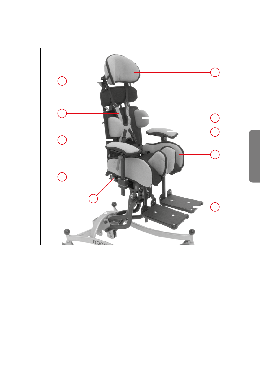
4. Modules overview
10
1
9
8
7
6
1 Head rest
2 Lateral side supports
3 Arm rests
4 Seat shell
5 Foot rests
6 Trapezoidal adapter
7 Lap belt
8 Back rest
9 Chest harness
10 Strap guides
2
3
4
English
5
MODULES OVERVIEW 39
Page 40

5. Combination options
MAGICLIGHT can be combined with the following undercarriages:
Indoor and outdoor use
ROOMY NEW EDITION (12˝ / 16˝ wheels))
SIMPLY LIGHT
SIMPLY
MINY
For indoor use
ROOMY NEW EDITION
ROOMY
6. Technical data
Size 0 Size 1 Size 2 Size 3
Total weight approx. 2.5 kg approx. 3 kg approx. 4 kg approx. 7 kg
Max. load 20 kg 25 kg 35 kg 45 kg
Max. patient height approx. 105 cm approx. 120 cm approx. 135 cm approx. 150 cm
Max. overall exterior
width (without arm rests)
Abduction angle /
Leg support shells
Total exterior height,
incl. trapezoidal adapter
Back angle adjustment -10° to +30° C -10° to +30° C -10° to +30° C -10° to +30° C
Seat width 19 - 25 cm 19 - 25 cm 25 - 31 cm 31 - 36 cm
Seat depth 16 - 19 cm 19 - 25 cm 25 - 31 cm 31 - 36 cm
Back height
(normal version)
Back height (long version) 34 - 40 cm 34 - 40 cm 40 - 46 cm 46 - 52 cm
Height of lateral side
supports, as measured
from seat cushion, for
normal back unit
36 cm 36 cm 41 cm 46 cm
-10° to +25° C -10° to +25° C -10° to +25° C -10° to +25° C
42 cm 42 cm 46 cm 53 cm
29 - 35 cm 29 - 35 cm 35 - 41 cm 41 - 47 cm
17 cm min.
22 cm max.
17 cm min.
22 cm max.
22 cm min.
27 cm max.
28 cm min.
35 cm max.
40 COMBINATION OPTIONS
Page 41

Size 0 Size 1 Size 2 Size 3
Height of lateral side
supports, as measured
from seat cushion, for
long back unit
Width between lateral
side supports
17 cm min.
27 cm max.
13 cm min.
19 cm max.
7. Safety instructions
Always follow the operating guidelines and safety instructions for the
undercarriage, to which your MAGICLIGHT is mounted�
It is never permitted to transport the patient in the seat shell when
traveling by car!
Please use a special vehicle seat that meets the applicable specifications
for traveling by car� The seat shell is only permitted to be transported by
vehicle if it is unoccupied and must be properly secured�
We would like to expressly point out that seat shell occupants must be
secured at all times by means of suitable restraint systems (straps)!
Always make sure that the seat shell is securely connected to the undercarriage�
Always contact your local dealer or your interCo team should you have
any questions about your MAGICLIGHT�
Perform periodic inspections of all threaded connections on your MAGICLIGHT� Consult your authorized local dealer in the case of any doubts�
Have any necessary modifications or additions performed by your local
dealer�
It is not permissible for any parties other than the manufacturer to make
additions or modifications to your MAGICLIGHT and any cases that should
become known shall be subject to legal action� Likewise, the warranty obligations of interCo GmbH shall cease to apply in such cases and any liability
claims directed at the manufacturer shall no longer be valid�
MAGICLIGHT is only approved for its intended use�
Seat units are only permitted to be mounted to the undercarriage in the
specified direction�
Do not use the foot rests or the leg support when getting into or out of a
seating system� The foot rests or leg support should be folded up and out
of the way or removed beforehand�
The patient, the seating system, and the undercarriage must be carried
separately when using stairs�
17 cm min.
27 cm max.
13 cm min.
19 cm max.
22 cm min.
32 cm max.
18 cm min.
24 cm max.
28 cm min.
40 cm max.
23 cm min.
29 cm max.
English
SAFET Y INSTRUCTIONS 41
Page 42

It is not permitted to carry the undercarriage with mounted seating system
while occupied
by a patient! Make sure that the patient is secured and will not fall out of
the chair when lifting or lowering the chair as well as prior to any adjustment to the inclination angle of the seat�
It is not permitted to hang bags on the seating system�
Never leave the patient unattended if he or she is not securely strapped in
place�
Persons with impaired vision are not permitted to operate or adjust the
MAGICLIGHT seating system�
Exposure to sunlight may cause the cushions and metal parts on the MAGICLIGHT to become excessively hot and could burn the patient�
Be careful around open flames and take precautions against the careless
use of cigars, pipes, and cigarettes� Dropping embers and burning ashes
could cause cushions and covers to smolder and catch fire�
8. Caution symbols
Please observe the caution symbols listed below and their meanings�
The symbols listed below are also on the product�
Important: Special attention
Important: Return to intended location following use
1
Important: Inspect screws to ensure that they are secure;
2
re-tighten, as necessary
Important: Check the mounting position and adjust, as necessary
3
Important: Inspect levers to ensure that they are secure;
4
re-tighten, as necessary
42 CAUTION SYMBOLS
Page 43
9. Quickguide
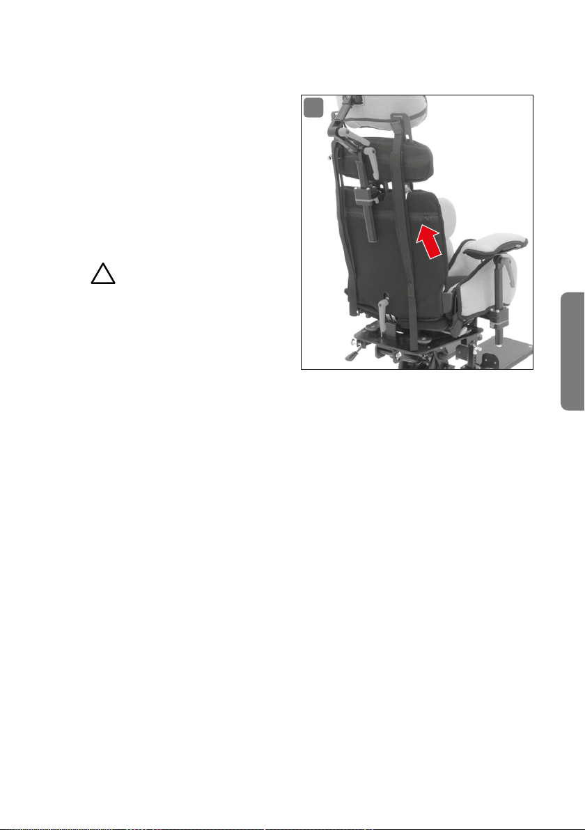
There is a pocket on the back rest
of your MAGICLIGHT containing a
QuickGuide (Fig� 2)� This QuickGuide provides the user with quick
and reliable information about
simple adjustment options, which
users can perform on their own
without the need to consult the
manufacturer or dealer�
Important!
1
In order to ensure that the simple
adjustment options can also be
performed by different operators
the Quick-Guide must always be
kept in your MAGICLIGHT�
The QuickGuide must be returned to the pocket provided for this purpose following use�
2
English
QUICKGUIDE 43
Page 44
10. Operation / adjustment / assembly
10.1 Trapezoidal adapter
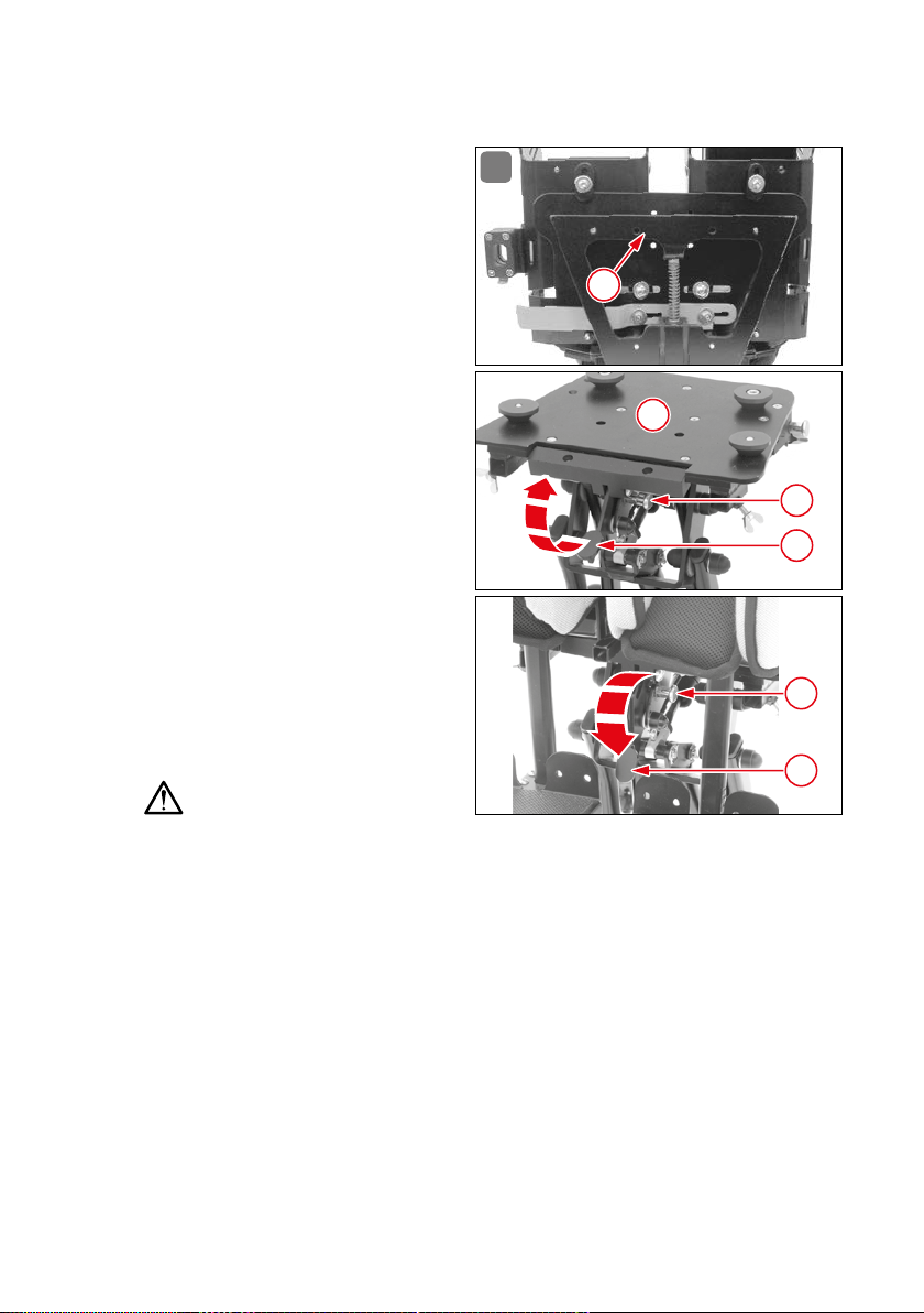
The trapezoidal adapter system
(Fig� 3), consisting of the trapezoi-
dal adapter (1) and the trapezoidal
adapter receptacle (2), connects
the MAGICLIGHT to compatible undercarriages or wheelchairs� Pull
out the spring-loaded catch mechanism (1) on the undercarriage and
rotate it 90°, pull down on the snap
cam (2), place the MAGIC LIGHT on
the undercarriage and slide it forward as far as it will go� The guide
unit on the trapezoidal adapter system ensures precise positioning of
the MAGICLIGHT on the undercarriage� Then press up on the snap
cam (2) and turn the spring-loaded
catch mechanism (1) another 90°
until it engages� MAGIC LIGHT is
now securely attached to the un
dercarriage�
Important!
3
1
2
3
4
5
-
6
The spring-loaded catch mechanism can only be secured if the MAGICLIGHT is
positioned correctly and the snap cam is in the proper position� If the springloaded catch mechanism is unable to be secured, then check to ensure that the
trapezoidal adapter system has been pushed forward as far as it will go on the
undercarriage; then push the snap cam up as far as it will go and secure the
spring-loaded catch mechanism� If your MAGICLIGHT is not secured correctly,
then it could slide off the undercarriage, possibly injuring the patient and damaging your MAGICLIGHT� MAGICLIGHT should only be secured and removed from
the undercarriage while unoccupied by the patient�
10.2 Tool
The standard equipment supplied with the MAGICLIGHT includes the Allen wrench
(size 4) tool� This tool (Fig� 4) can be used to perform all adjustments to the MAGIC-
44 O PERAT ION / ADJU S TMEN T / ASSEM BLY
Page 45
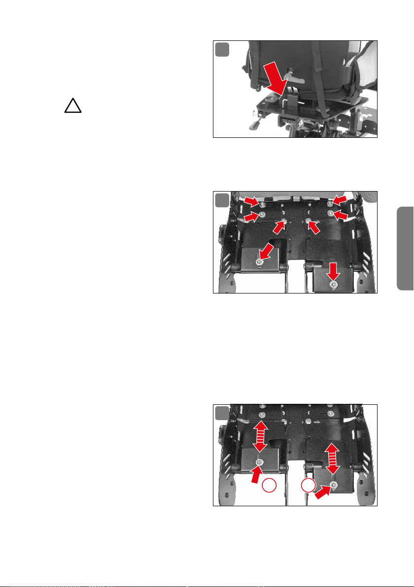
LIGHT� An additional open-ended
wrench (size 8) is only required for
4
disassembly and repositioning of
the lateral side support cushions�
Important!
1
The Allen wrench must always be
kept with your MAGICLIGHT in order to enable the performance of any necessary adjustments to the seat or immediately tighten any threaded connections that may have become loose�
10.3 Seat shell/adjusting screws
The seat shell (Fig� 5) is made of
5
light-weight aluminum and its width
and length are each able to be individually adjusted by up to 5 cm� In
order to be able to perform a precise adjustment the patient’s individual measurements must first be
taken� Due to the fact that the width
of the seat is adjusted without cushions, it is necessary to add 2 cm per cushion to the measurements� In order to
achieve ideal stability it is advisable to adjust one side first and then the other side�
10.4 Adjusting the seat shell
Remove the seat overlay, the side cushions, and the abduction cushion�
Loosen the adjusting screws with the Allen wrench (size 4)�
10.4.1 Seat depth (thigh length)
Adjusting the seat depth (Fig� 6):
After loosening the adjusting
6
screws (1 / 2), you will be able
to slide the plates lengthwise
for leg length adjustment and
adjust them to the individual
1 2
measurements of the patient�
English
OPER ATION / ADJU STMEN T / ASSEM BLY 45
Page 46
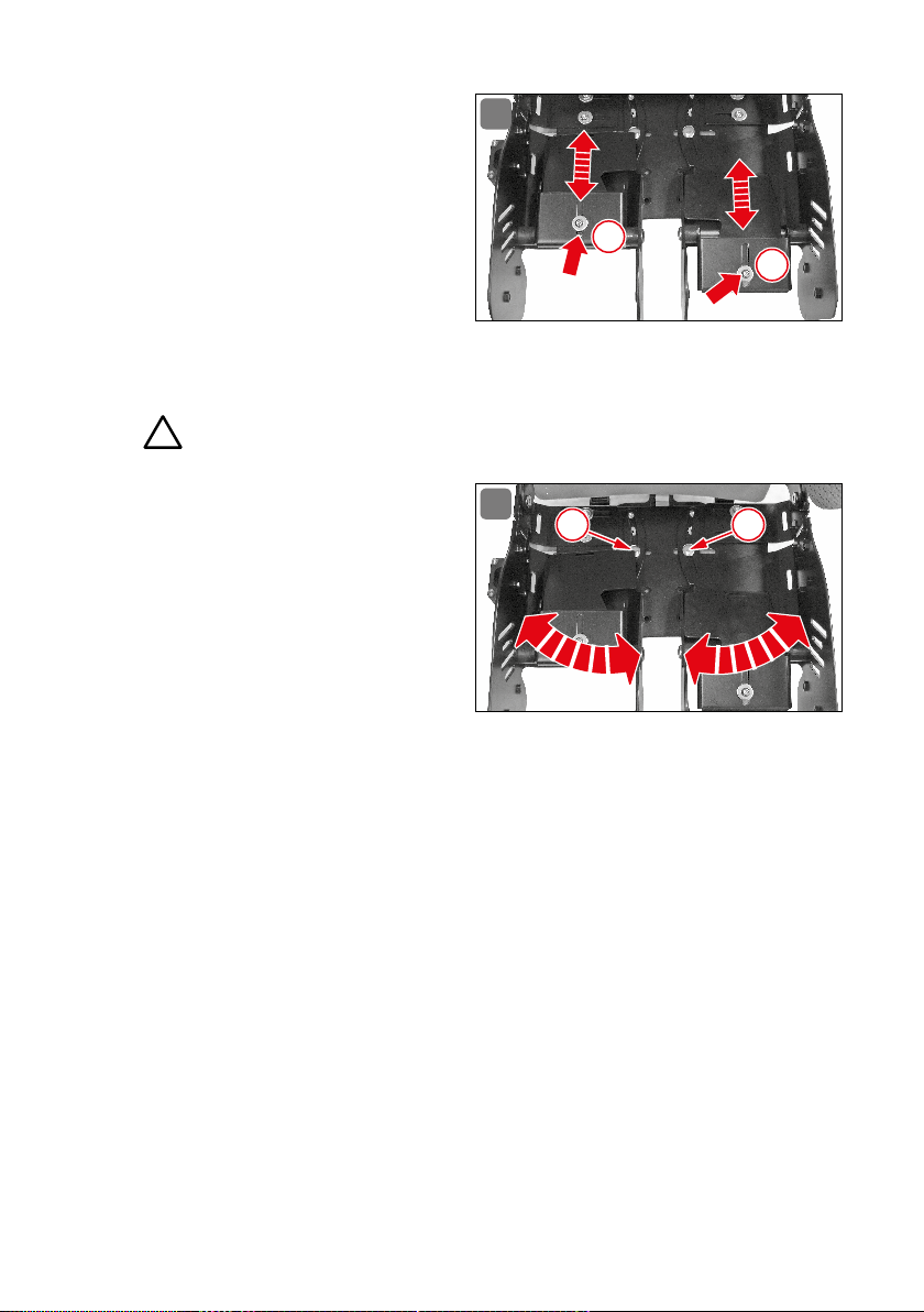
10.4.2 Seat mold
Adjusting the seat mold (Fig� 7):
Loosen screws (1 / 2) with the
Allen wrench (size 4)�
You will now be able to slide
the plates lengthwise for seat
mold adjustment and adjust
them to the individual measurements of the patient�
Re-tighten screws with the
Allen wrench (size 4)�
Important!
2
7
1
2
10.4.3 Abduction
Once the adjusting screws for the
abduction
(3 / 4)
have been loosened
8
3 4
the abduction guides (Fig� 8) can
also be variably adjusted in order
to place the patient’s legs in a parallel position or at a different angle�
The angle of the leg support shells
can be adjusted within a range of
-10° to + 25°�
Special feature: If the patient requires an abduction adjustment on one side, then
it is possible to place the other leg parallel to this abduction adjustment angle�
This angular range is adjustable by up to 5°�
10.4.4 Seat width
Adjusting the seat width (Fig� 9):
Open the back cushions below and pull them up above the red clamping
lever�
Loosen screws (1 through 4) on the back unit and
(5 through 8) on the seat shell using the Allen wrench (size 4)�
Adjust the seat width to the measurements of the patient and ensure the
correct positioning of the back rest�
Re-tighten screws (1 through 4) on the back unit and (5 through 8) on the
seat shell using the Allen wrench (size 4)�
46 OPER ATIO N / ADJU STME N T / ASSEM BLY
Page 47
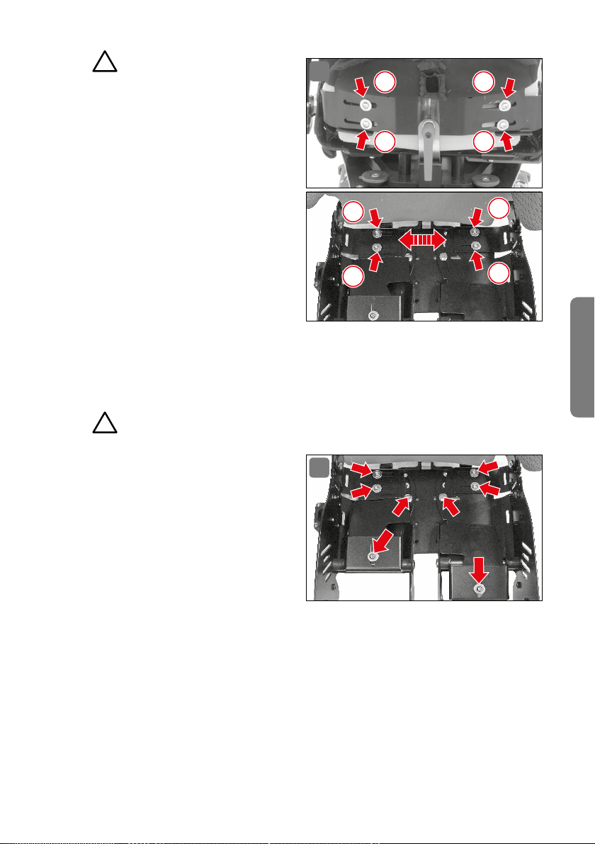
Important!
2
After you have tightened the screws,
check once more to ensure that the
seat and back rest are in the correct position in order ensure that
the patient is seated comfortably
in the MAGICLIGHT� Readjust, as
necessary�
Pull the back cushions back
down over the red clamping
lever and close them�
10.4.5 Tighten the adjusting screws
Tighten the adjusting screws
with the Allen wrench (size 4)�
Check all adjustable parts once more to ensure that they are secure and
re-tighten screws, as necessary�
Important!
2
9
1
2
7
8
3
4
5
6
English
The adjusting screws (Fig� 10)
are the most important anchor
age points on the MAGICLIGHT
and they must be inspected on
a regular basis to ensure that
they are secure� This is the only
way to maintain the adjustments
in accordance with the patient’s
measurements and ensure that
the patient is seated correctly in
the MAGICLIGHT�
Re-attach the abduction cushion�
Re-attach the side cushions�
Replace the seat overlay�
Make sure that all of the cushions are attached without any creases in order to
protect the patient against pressure areas� The seat overlay is designed to fit all
OPER ATION / ADJU STMEN T / ASSEM BLY 47
10
-
Page 48
possible seat settings� It is attached
to the seat shell with a Velcro strap
and can be easily removed�
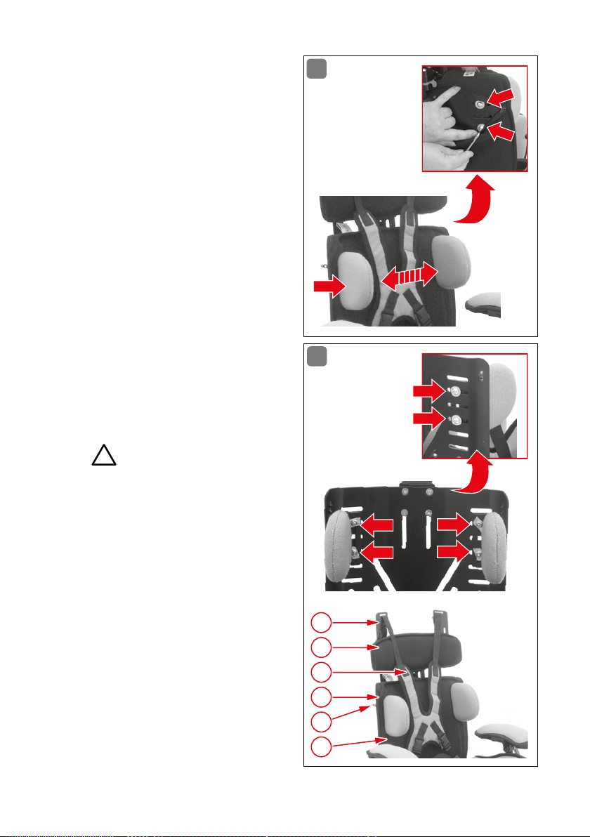
10.5 Back rest/Lateral side supports
It is best to adjust the lateral side
supports (Fig� 11) with the patient
seated in the chair� In order to achieve an ideal level of support, adjust
one side first and then the other�
Unzip the cushion on the
lower back rest�
Loosen the 2 screws on each
side with the Allen wrench
(size 4)�
Adjust the lateral side supports to the measurements
of the patient�
Re-tighten screws with the
Allen wrench (size 4)�
Zip the zipper closed�
Important!
2
11
12
If the adjustment options for the
lateral side supports (Fig� 12) are
not sufficient for the patient in the
standard position, then the lower
back rest provides other alternative positions� In order to make use
of these alternative positions the
cover on the lower back rest must
be completely removed�
Removing the head rest (see
Fig� 16)
Loosen the chest harness
strap (1) at the clip buckles (2)�
Unzip the zipper (3) on the
lower back cushion�
48 OPE R AT ION / ADJU S TM ENT / A SS EMBL Y
2
4
1
5
3
5
Page 49

Loosen the upper back rest (4) and pull it up and off�
Unzip the zippers (5) on the back cover above and below the lateral side
supports�
Open the back cover and pull up on it to remove it�
Remove foam cushion�
Remove lateral side supports (using Allen wrench [size 4], open-ended
wrench [size 10])�
It is now possible to reattach the lateral side supports in accordance with the
patient’s individual measurements�
Replace foam cushion�
Replace back cushion cover and close it below�
Zip the zippers (5) closed on the back cover above and below the lateral
side supports�
Replace upper back rest (4) and align it parallel to the lower back rest�
Re-tighten screws on upper back rest�
Re-tighten the chest harness strap (1) at the clip buckles (2)�
Insert head rest and adjust it to the correct height (see Fig� 15)�
Place patient in the chair�
Adjust lateral side supports and re-tighten screws�
Zip the zipper closed on the back cover�
English
2 3
Important!
10.6 Back rest/Back height
The back rest (Fig� 13) consists of two sections, a lower fixed section connected
to the seat shell using pivot points and the upper, moveable section that is able
to be adjusted� This enables the back height to be increased by up to 5 cm�
Only the upper section is adjusted to the height of the patient� This design has
the advantage of enabling the strap guide tabs and the straps to be automatically
adjusted along with the back height�
Adjusting the back rest:
Remove the head rest (see Fig� 15)
Unzip the back zipper on the lower back rest�
Loosen the 2 screws with the Allen wrench (size 4)�
Adjust the back height to the measurements of the patient�
OPER ATION / ADJU STMEN T / ASSEM BLY 49
Page 50
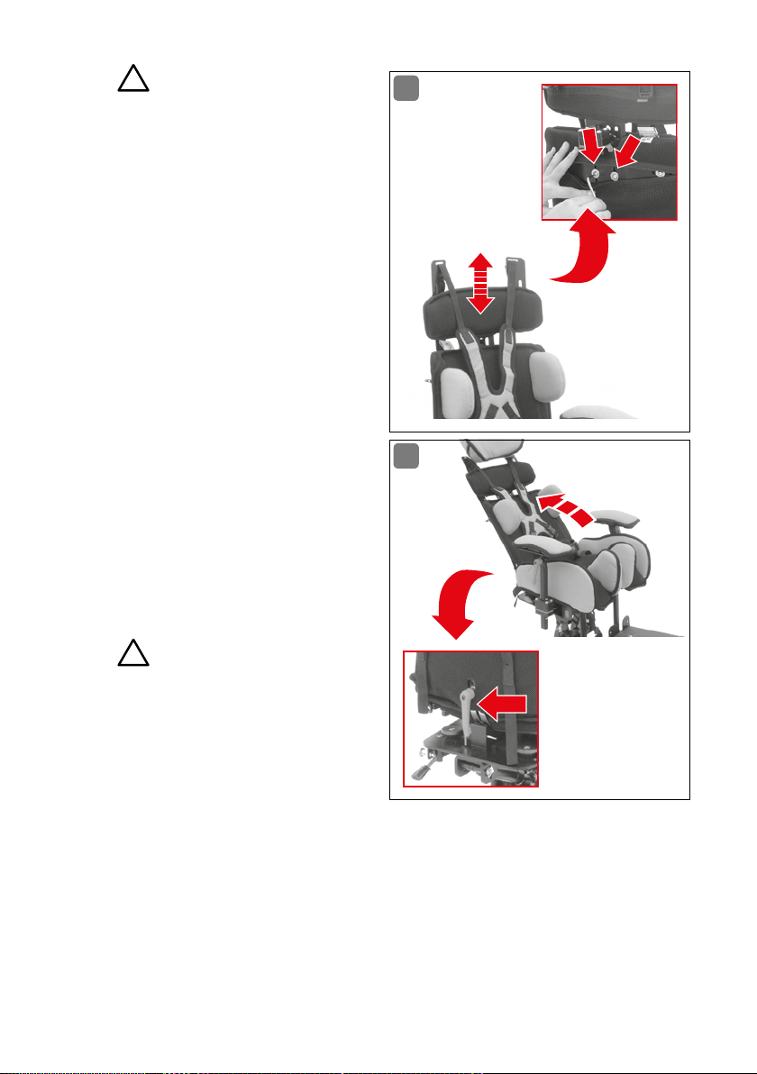
Important!
2
The upper back rest must be positioned parallel to the lower back
rest in order to ensure precise guidance of the straps�
Re-tighten screws with the
Allen wrench (size 4)�
Zip the zipper closed�
Replace head rest and adjust
it to the correct height
(see Fig� 15)�
10.7 Back rest/Inclination angle
The inclination angle of the back
rest (Fig� 14) can be adjusted to
meet the needs of the patient� The
back rest has a fixed adjustable
range of -10° to +30°� Turn the red
clamping lever two revolutions on
the lower back rest to loosen it,
adjust it to the correct angle, retighten clamping lever�
13
14
Important!
4
If you want the back rest to be
moveable, then this option can be
selected and adjusted using the dynamic back rest (see Fig� 21)�
10.8 Back rest/Head rest
It is possible to adjust the head rest (Fig� 15) individually to the patient’s head
using the snap rod and the two joints� The height of the head rest can be easily
and securely adjusted by pressing the snap rod button (4) on the head rest holder
(1)� The rod will snap into the next position by pulling slightly on the head rest and
pressing the button briefly� The head rest can be completely removed by pressing
the snap rod button and holding it down�
50 O PERAT ION / A DJU S TM ENT / A SS EMBL Y
Page 51
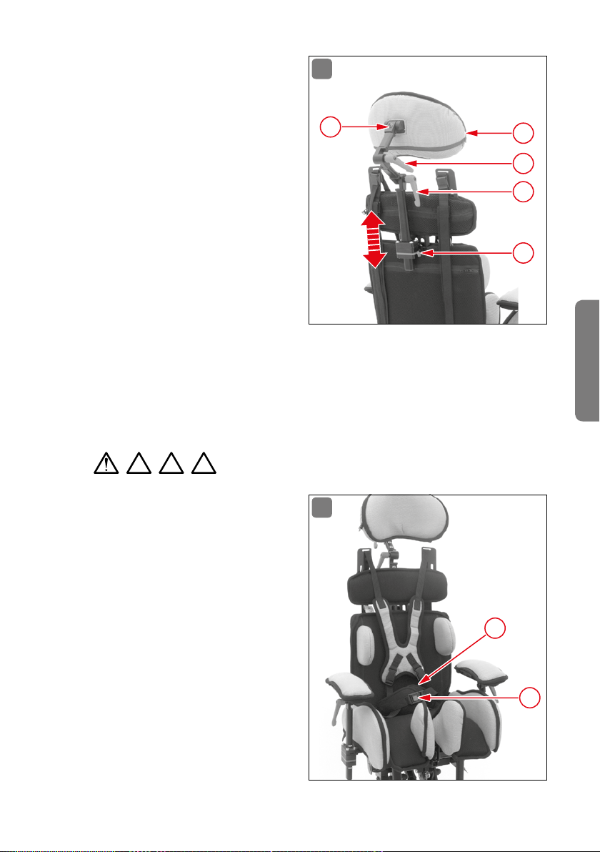
The two joints are intended for further adjustment of the head rest�
They enable perfect positioning of
the patient’s head� The joints are
able to be adjusted individually by
turning the two clamping levers
(2 + 3) two revolutions each� Then
re-tighten the two clamping levers�
If it is also necessary to adjust the
inclination of the head rest, then
loosen the individual retaining
screw (5) with the Allen wrench
(size 4) and set the inclination angle�
To wash the head rest cover, completely remove the uppermost joint from the support bar (using the Allen wrench
[size 4]), then unzip the zipper and remove the head rest cover by pulling it up
and over the support bar� Replace the head rest cover after washing it by pulling it over the support bar and onto the head rest cushion, zip the zipper closed
and secure the head rest back on the support bar (using Allen wrench [size 4])�
15
5
1
2
3
4
English
2 3 4
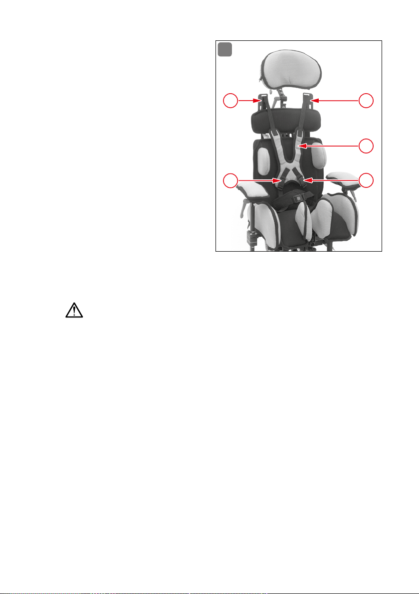
10.9 Hip belt
The standard equipment supplied
with the MAGICLIGHT includes
a 4-point hip belt (Fig� 16) with a
unisex neoprene cushion (1)� Once
the hip belt has been adjusted to
the patient secure the belt with the
buckle and tighten with one hand
using the belt eyelets� This enables
the operator to support the patient
with the other hand� The hip belt
can be unbuckled by pressing on
the red button (2) on the buckle�
OPER ATION / ADJU STMEN T / ASSEM BLY 51
Important!
16
1
2
Page 52
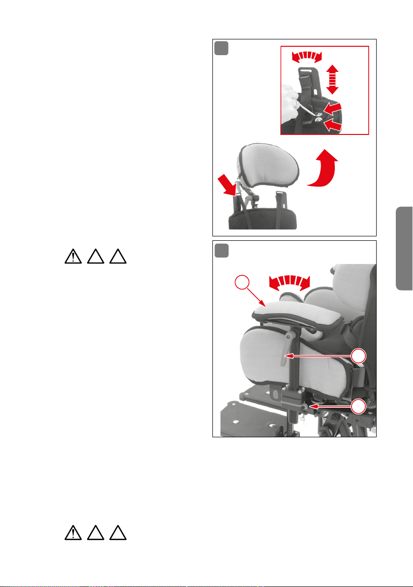
10.10 Back rest/Chest harness
The standard equipment supplied
with the MAGICLIGHT includes a
unisex upholstered chest harness
(1) (Fig� 17)� In order to be able to
place the patient in the seat loosen
the lower clips (2) and the lower
clip buckles (3) on the strap guide
plates�
Fold back the chest harness
(1) and place the patient in the
seat�
Pull the chest harness (1) over
the patient’s head from behind
and secure the strap to the
clips (2)�
Tighten the lower straps
slightly and secure with the clip buckles (3)�
Check upper strap arrangement�
Important!
17
3
3
1
2
2
Make sure that the straps are not pressing on the patient’s neck to avoid the risk
of strangulation�
Tighten upper straps and secure patient�
If upper strap placement is not optimal, then readjust the strap guide plates
(see Fig� 18)�
10.11 Back rest/Strap arrangement
MAGICLIGHT comes equipped with strap guide plates (Fig� 18) which enable individual strap adjustment and optimal arrangement of the chest harness straps
for each patient� The strap guide plates are mounted on the upper back unit in
order to automatically ensure the same default strap arrangement when the
back height is adjusted� The arrangement of the chest harness straps should be
centered over the collar bone�
52 O PER ATIO N / ADJU STME N T / ASSEM BLY
Page 53
Adjusting the strap arrangement:
Unzip the zipper on the upper
back unit cushion�
Loosen the 2 screws on each
side with the Allen wrench
(size 4)�
Adjust the strap guide plates
to enable optimal arrangement
of the chest harness straps�
Re-tighten screws with the
Allen wrench (size 4)�
Check strap arrangement on
the patient�
Readjust, as necessary�
Zip the zipper closed on the
upper back unit cushion�
18
2 3
Important!
Incorrect arrangement:
Straps arranged too closely
19
3
around the neck – risk of
strangulation�
Straps arranged too loosely
around the shoulders – straps
could slip off the patient’s
shoulders; the patient is then
no longer secured and could
fall out of the chair, resulting
in possible injury�
10.12 Arm rests
The arm rests (Fig� 19) are individually and variably adjustable for each patient� The height of the arm rests (3) is
adjusted using the incremental height adjustment mechanism� To do so, press the
lever (1) and adjust the arm rest to the desired height� The angle of the arm rest is
adjusted using clamping levers (2)� Turn the clamping lever two revolutions to loosen
it, adjust the arm rest to the correct angle, and re-tighten the clamping lever (2)�
3 4
Important!
English
2
1
OPER ATION / ADJU STMEN T / ASSEM BLY 53
Page 54
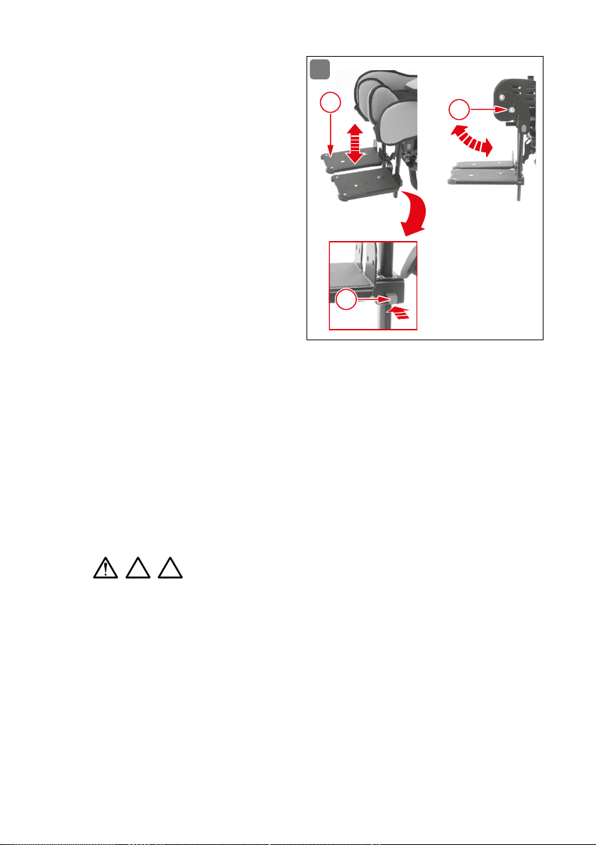
10.13 Foot rests
The foot rests (Fig� 20) are mounted
to the abduction guides on the
MAGICLIGHT� They are equipped
with swivel bearings to enable the
greatest possible range of motion
for the patient, as needed� A clamping screw (3) on the side of the seat
shell enables the foot rests to be
secured� The foot rests can be secured vertically or at an individual
angle�
20
2
3
The foot rests are adjusted using
a ratcheting height adjustment
mechanism� They can be adjusted
individually to the corresponding height in accordance with the measurements of the patient� The ratcheting
mechanism ensures that the foot rests can also be set to the same height without
the need for elaborate measuring�
By pressing briefly on the corresponding button (1) the foot rest (2) will snap into
the next position; by pressing on the corresponding button and holding it down
(1) the foot rest can be pulled down and removed�
The foot rests can be configured individually using the extensive accessories,
such as foot restraints or upholstery applications�
3 4
Important!
1
11. Daily use
11.1 Dynamic back rest
The back units of the seat (Fig� 21) are interconnected by three pivot points on
the MAGICLIGHT� The back rest is moveable and its compression spring enables
it to readily absorb the sudden force exerted when the patient stretches� After
stretching the patient is returned to the original position� The dynamic back rest
is deactivated among the standard settings�
54 DAILY USE
Page 55
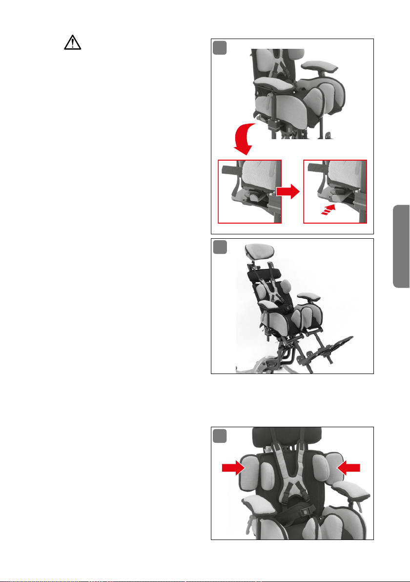
Important!
Red lever in standard position
Dynamic back rest is deactivated and back rest is fixed in
place
Red lever inserted
Dynamic back rest is activated
and back rest is moveable
11.2 Supine position
It is possible to recline the back
rest (Fig� 22) to an angle of up to
30° in order to provide the option
of a relaxed supine position� To do
so, loosen the red clamping lever
on the lower back rest, adjust it to
the desired angle, and re-tighten
the clamping lever (Fig� 14)� The
foot rests can also be adjusted to
provide further support in the supine position and ensure that the
patient enjoys the greatest possible
comfort (see Fig� 20)�
21
22
English
12. Optional accessories
12.1 Upper arm supports
The upper arm supports (Fig� 23)
limit the range of motion� The patient is no longer able to move his
or her arms backwards, between
the back rest and arm rest� The
standard equipment includes the
upper arm supports mounted on
the back rest� The back rest and
OPTIONAL ACCESSORIES 55
23
Page 56
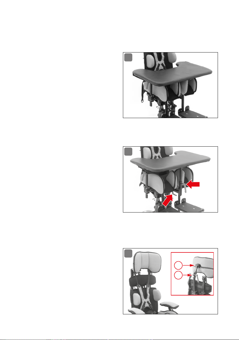
back cushions come equipped for subsequent attachment of the upper arm supports� The upper arm support cushions are removable and washable� They are
supplied as a set, including mounting instructions and fastening materials�
12.2 Therapy tray table with Velcro
attachment
The basic version of the therapy tray
table (Fig� 24) is placed on the arm
rests, adjusted to the patient, and
secured to the arm rest cushions
with the Velcro straps provided� In
addition, the therapy tray table can
also be secured to the back rest
with a strap�
It is supplied with mounting instructions�
12.3 Therapy tray table, attachable
The reinforced version of the therapy tray table (Fig� 25) is mounted to
the seat shell� To do so, a separate
bracket is secured to the underside
of the seat shell in accordance with
the assembly instructions� Once
the therapy tray table has been attached to the bracket, its height and
distance can be adjusted by sliding
it, enabling it to be adapted to the individual needs of the patient�
24
25
It is supplied with mounting instructions�
12.4 Head rest, standard
The head rest (Fig� 26) is equipped
with a clamping lever (1) in order to
adapt it to the patient� The support
bar comes equipped with a height
adjustment ratcheting mechanism;
the angle of the head rest can be
adjusted using a joint with a locking
screw (2)�
56 OPTIONAL ACCESSORIES
26
2
1
Page 57
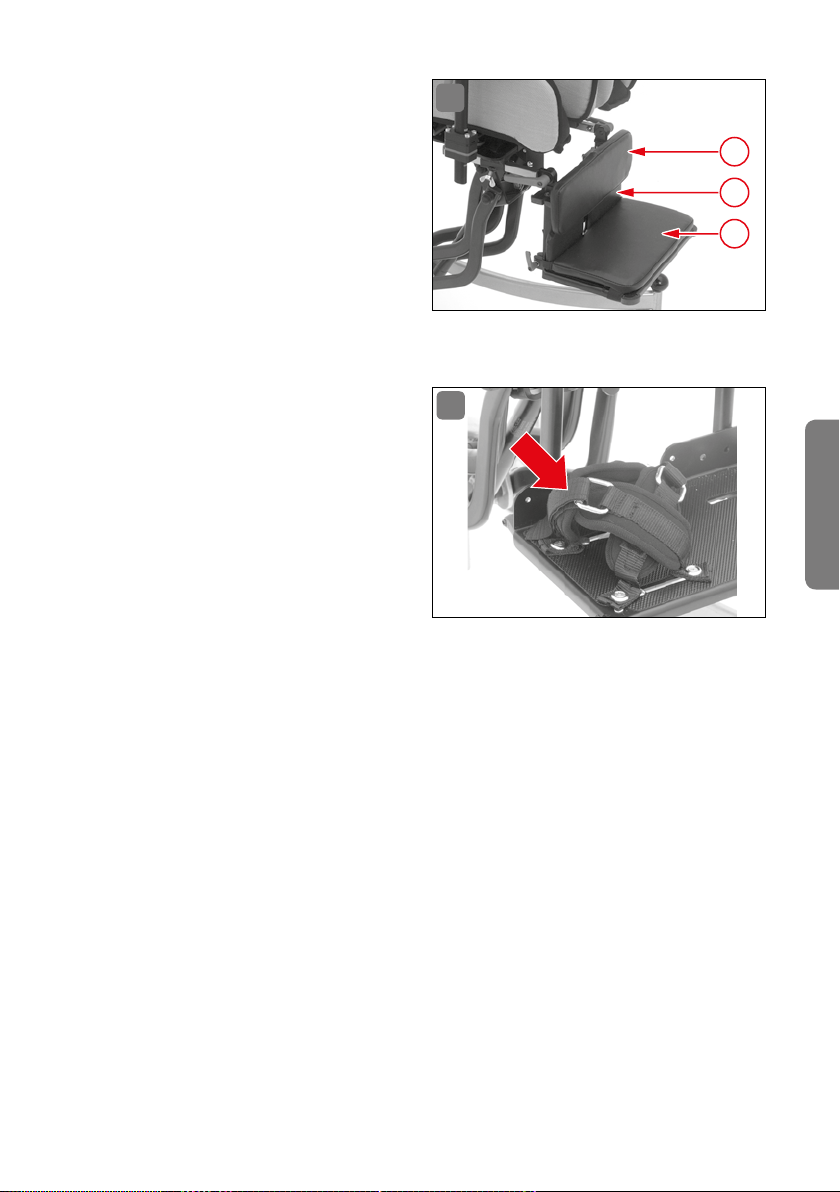
12.5 Leg rest
ALULINE leg rest system (Fig� 28)
with incrementally adjustable
holder for leg rest system, com
plete version, powder coated in
black, includes corner guards and
foot rest overlay� Before mounting it to the undercarriage, please
check to ensure that the undercarriage is compatible with ALULINE�
It is supplied with mounting instructions�
28
-
3
2
1
12.6 Leg rest cushions
ALULINE (Fig� 30) is able to be fur-
29
ther configured by attaching the
following cushions:
Foot rest cushion (1)
Heel stop cushion (2)
Calf support (3)
12.7 Foot restraints
The following foot restraints are
available from interco for use with the foot rests or the ALULINE leg rest system (Fig� 31):
Foot straps with padded instep made of Velcro/fleece
Foot straps with deflection roller and padded instep
Foot gaiters made of neoprene
Foot gaiters with forefoot restraint made of neoprene
“Foot gaiters with forefoot restraint made of neoprene” is the version shown�
They are supplied as a set, including mounting instructions�
English
OPTIONAL ACCESSORIES 57
Page 58
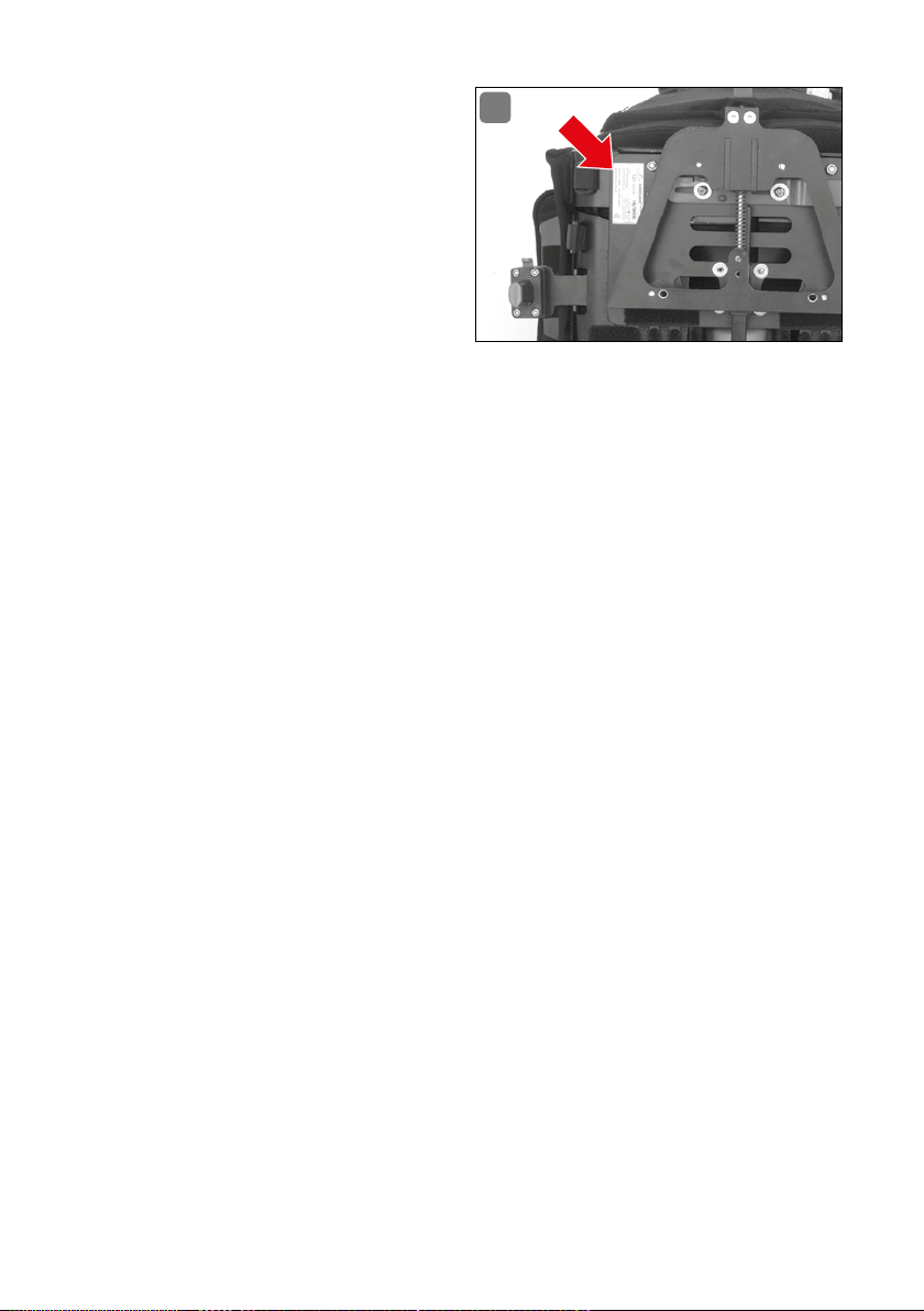
13. Rating plate
The rating plate (Abb� 30) is at-
tached to the underside of the seat
shell� Here you will find the serial
number and size of your MAGICLIGHT�
Please provide this information
with any replacement part orders
or if you require accessories!
30
14. Maintenance / inspection
Periodic maintenance and inspection of the seating system is indispensable for
the well-being of the patient� Please inspect your MAGICLIGHT regularly for wear
or defective parts�
Prior to each use:
Inspect all cushions for damage and ensure proper placement�
Inspect the straps on the chest harness and lap belt for wear and ensure
secure support�
Important: Worn out straps must be replaced immediately�
Inspect all moveable parts to ensure that they are securely in place�
Inspect the settings of the patient’s seat�
Important: Readjust settings, as necessary�
Every 4 weeks (or more frequently, depending on frequency of use):
Inspect the seat undercarriage for damage�
Inspect the compression spring of the dynamic back rest�
Important: If the compression spring breaks, have it replaced immediately�
Inspect the spring plate on the back rest recline�
Important: If the spring plate breaks, have it replaced immediately�
Inspect all threaded connections and clamping levers�
Important: Have any damaged clamping levers replaced immediately�
Every 6 months (or more frequently, depending on frequency of use):
Complete MAGICLIGHT inspection by the medical supplies store or local dealer�
58 RATING PL ATE
Page 59
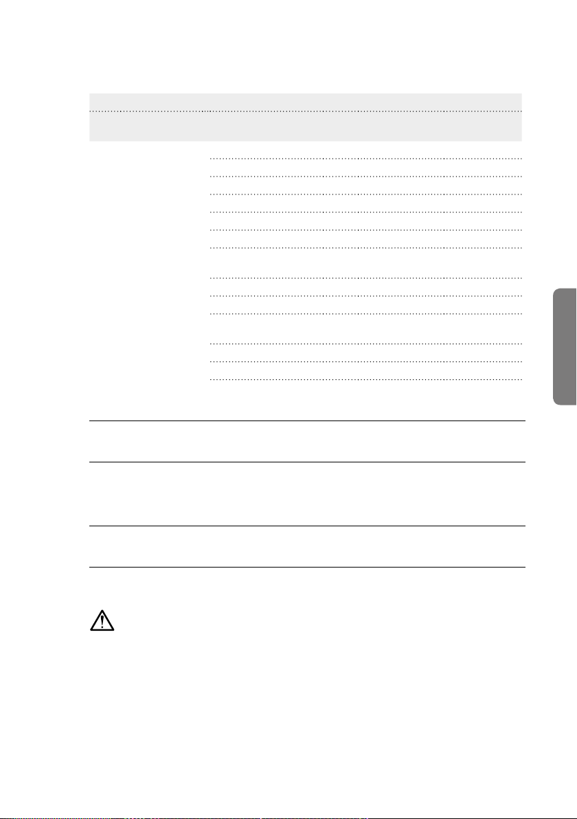
15. Service plan
Pos. Area Test
1 Seating system
2 Threaded
connections
3 Appearance
Maintenance performed by
Setting/
Function
Back recline
Dynamic back rest
Head rest
Arm rests
Foot rests
Trapezoidal adapter
Screws tightened
Rust spots
Finish
Fabric seams
(position/appearance)
Rating plate
Cleanliness
OK Damages/
Distortions
Exchange/
Replacement
English
Place/Date Signature Next servicing
Maintenance performed by
Place/Date Signature Next servicing
Important!
Repairs, adjustments, additions, and maintenance should only be performed by
authorized partners (medical supplies stores or local dealers) or by interCo GmbH�
Please call Customer Service to request a partner near you�
Tel�: +49 (0) 22 43 / 88 07-0
SERVICE PLAN 59
Page 60

16. Materials / cleaning / care
The abduction, side, seat, and back cushions are manufactured using cold foam
HE40 at a thickness of 20 or 30 mm� The lateral side support cushions are made
of composite foam RG140 at a thickness of 10 mm�
The covers are made of high-quality spacer fabrics� You can play a role in maintaining the appearance of the valuable covers of your seating system by
cleaning, vacuuming or carefully brushing them regularly before stains set in�
Wiping up spilled liquids right away with an absorbent cloth - the longer
you wait to do so, the more difficult it will be to clean!
In the case of any dried spills, it is usually helpful to apply a small amount
of a mild liquid detergent for delicate fabrics to a cloth and dab it on the
spill (never rub)�
Important: Never apply detergent directly to the cover; always apply it to a cleaning cloth� Wipe gently with clean water, if necessary� Please note: Bleach or whiteners should not be applied to the material� The material should be exposed to
as little direct sunlight as possible� All of the fabrics for our covers are washable
at 30 °C� Use a detergent for delicate fabrics or a gentle dry-cleaning process to
clean the covers� Never dry the covers in the dryer! Iron at a low temperature�
If you should wish to wash the seat shell cover frequently, then it is advisable to
have an auxiliary cover to put on the seat shell while washing the other cover�
Ask about this at your medical supplies store� Please clean additional parts
with a mild household soap solution� The standard base of the seating system is
covered with a high-quality, durable plastic coating� Please clean it with soapy
water and a soft sponge� Avoid using aggressive or abrasive cleaning agents, as
these can damage the surface of the plastic coating�
Disinfection
Please use a water-based agent for disinfection, e�g� Terralin, Quartamon Med or
Sagrotan Original concentrate� Please observe the manufacturer’s instructions
for use when using these agents�
It is best to clean plastic parts with a commercially available plastic cleaner
(please observe the product information for the cleaning agent)� If the finish
should become scratched, it is possible to repair such scratches with a touchup stick�
60 M AT ERI A LS / CLEANI NG / C AR E
Page 61
17. Declaration of conformity
EU-Declaration of Conformity for Medical Devices
Name of the manufacturer: interco GmbH
Gesellschaft zur Planung und Vertrieb
von Rehabilitationshilfen mbH
Address of the manufacturer: Im Auel 50
53783 Eitorf GERMANY
We hereby declare that the device
Article description: MAGICLIGHT, size 0-3 (Art� no�: 37100-37103)
Version/model: Modular, adjustable seating system,
measurements according to the table,
equipment according to the definition
Commission: Serial production
conforms to the pertinent provisions of the directive listed below:
Medical Device Directive 93/42/EEC, Annex I and VII
Eitorf, 06 October 2008
English
Michael Markwald
CEO
DECLARATION OF CONFORMITY 61
Page 62

18. Warranty
In addition to our General Terms and Conditions, your product comes with a 1-year
warranty from the date of purchase� Please keep your receipt as proof of the start
of the warranty period� Once you send in your warranty card we will grant you an
additional year under the manufacturer’s warranty, resulting in a total period of
two years under warranty� Defective or damaged parts will be repaired or replaced
free of charge during the warranty period� The warranty excludes design-related
modifications as well as parts subject to wear (cushions and covers)�
Important!
We will accept no liability in the case of damages associated with our product in
combination with third-party products of any kind, some of which may involve
significant risks, with the exception of products by other manufacturers, which we
have expressly approved� The warranty also excludes any defects occurring as the
result of normal wear, excessive stress, deliberate damage, as well as misuse�
Non-observance of the operating guidelines, improperly performed maintenance
and repairs, and especially any technical modifications and/or additions (attachments) without prior approval of interCo GmbH will void both the warranty as
well as the general product liability obligations�
Subject to technical modifications without notice�
62 WARRANTY
Page 63

19. Reuse
MAGICLIGHT is suitable for reuse� Before it is passed on, all the necessary cleaning and maintenance activities must be performed� When it is handed over, make
sure it is accompanied by all the documentation necessary for use (including
these instructions for use)�
20. Disposal
Please observe the applicable disposal regulations in your country when disposing of the packaging materials or any damaged parts�
Packaging
Cardboard: Waste paper collection or paper container
Styrofoam and foil/film: Yellow bin or yellow sack
Individual parts
Covers or cushions: Household waste
Plastic parts: In the containers/bins provided for each purpose based
on the respective information provided on the label
Metal parts: Container for metals
Discarded seating systems can also be returned to the medical supplies store
or local dealer�
English
DISPOSAL 63
Page 64

Notes
Page 65

Notes
WARRANTY CARD
English
Upon submission in this card we will extend the warranty on your MAGICLIGHT® to cover
a total of 2 years. Please fill out this warranty card carefully and completely and return
it to us. Thank you very much.
Payer/Health Insurance Fund:
Location of the payer:
Serial number:
Delivery date:
Name of the patient:
Street:
Postal code/Place:
Telephone*:
Email*:
*Optional
Page 66

Notes
REPLY CARD
SENDER
Name
Street
Postal code/Place
Please be
sure to
include
sufficient
postage!
RETURN ADDRESS
interco GmbH
Im Auel 50
53783 Eitorf - Germany
Page 67

Page 68

Gesellschaft für Planung und Vertrieb
von Rehabilitationshilfen mbH
Im Auel 50
53783 Eitorf
Germany
T. +49 2243 8807-0
F. +49 2243 8807-29
E. info@interco-reha�de
I. www�interco-reha�de
© interco GmbH, Eitorf, 2018
Stand März 2018
Technische Änderungen vorbehalten
Status as per March 2018
Subject to technical alterations
without prior notification
Zertifiziert nach
Certified as per
DIN EN ISO 9001:2015
Reg�-Nr� 73 100 357-1
DIN EN ISO 13485:2012
Reg�-Nr� 70 105 357-1
TÜV Hessen
interc o und Seat up you r Life! sind ein getragene M arken der inter co GmbH · interc o and Seat up you r Life! are reg istered tr ademarks of i nterco GmbH
 Loading...