

interco Ergoline Series, Ergoline Aktiv, Ergoline Passiv, Ergoline Carbon Operating Manuallines
Page 1
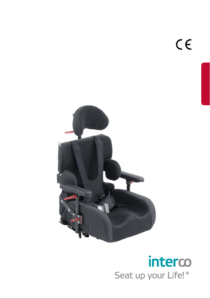
ERGOLINE®
ERGOLINE®
ERGOLINE Aktiv · ERGOLINE Passiv · ERGOLINE Carbon
Bedienungsanleitung
Operating Guidelines
03 / 2018
Page 2

Bedienungsanleitung ERGOLINE® CE
Operating Guidelines ERGOLINE® CE
Deutsch . . . . . . . . . . . . . . . . . . . . . . . . . . . . . . . . . . . . . ab Seite 3
English . . . . . . . . . . . . . . . . . . . . . . . . . . . . . . . . . . . from page 27
Page 3

Inhalt
1. Einleitung � � � � � � � � � � � � � � � � � � � � � � � � � � � � � � � � � � � � � � � � � � � � � � � � � � � � � � 4
2. Sitzschale ERGOLINE und lieferbares Zubehör � � � � � � � � � � � � � � � � � � � � � � � 4
3. Grundausstattung ERGOLINE � � � � � � � � � � � � � � � � � � � � � � � � � � � � � � � � � � � � � � 5
3.1 ERGOLINE-Sitzschale mit Maßpolsterung � � � � � � � � � � � � � � � � � � � � � � � � � � � 5
3.2 Die Verwendung der Sitzschale durch den Benutzer � � � � � � � � � � � � � � � � � � � 6
3.3 Fixierung in der Sitzschale � � � � � � � � � � � � � � � � � � � � � � � � � � � � � � � � � � � � � � � � 7
4. Armlagerung� � � � � � � � � � � � � � � � � � � � � � � � � � � � � � � � � � � � � � � � � � � � � � � � � � � 10
4.1 Armauflagen höhenverstellbar (Standardarmpolsterung) � � � � � � � � � � � � � 11
4.2 Armauflagen höhen- und winkelverstellbar (Standardarmpolsterung) � � � 11
4.3 Armpolster muldenförmig � � � � � � � � � � � � � � � � � � � � � � � � � � � � � � � � � � � � � � � � 11
4.4 Unterarmfixierung � � � � � � � � � � � � � � � � � � � � � � � � � � � � � � � � � � � � � � � � � � � � � � 11
4.5 Armlehnen ALULINE � � � � � � � � � � � � � � � � � � � � � � � � � � � � � � � � � � � � � � � � � � � � 12
5. Kopflagerung � � � � � � � � � � � � � � � � � � � � � � � � � � � � � � � � � � � � � � � � � � � � � � � � � � 12
5.1 Kopfstützenhalter gekröpft � � � � � � � � � � � � � � � � � � � � � � � � � � � � � � � � � � � � � � � 13
5.2 Kopfstützenhalter gerade � � � � � � � � � � � � � � � � � � � � � � � � � � � � � � � � � � � � � � � � 13
5.3 Kopfstützenhalter Konusverstellung � � � � � � � � � � � � � � � � � � � � � � � � � � � � � � � 13
5.4 Kopfstützenpolster � � � � � � � � � � � � � � � � � � � � � � � � � � � � � � � � � � � � � � � � � � � � � � 14
5.5 Kopfstützensysteme ALULINE � � � � � � � � � � � � � � � � � � � � � � � � � � � � � � � � � � � � 15
6. Beinlagerung � � � � � � � � � � � � � � � � � � � � � � � � � � � � � � � � � � � � � � � � � � � � � � � � � � 15
6.1 Abduktionskeil (Spreizkeil) � � � � � � � � � � � � � � � � � � � � � � � � � � � � � � � � � � � � � � � 15
6.2 Abduktionsgurt mit Steckschloss � � � � � � � � � � � � � � � � � � � � � � � � � � � � � � � � � � 16
6.3 Abduktionsgurt mit Umlenkrolle � � � � � � � � � � � � � � � � � � � � � � � � � � � � � � � � � � 17
7. Rumpffixierung � � � � � � � � � � � � � � � � � � � � � � � � � � � � � � � � � � � � � � � � � � � � � � � � � 18
7.1 Brustgurt mit Überschlaglasche � � � � � � � � � � � � � � � � � � � � � � � � � � � � � � � � � � 18
7.2 Brustgurt mit Umlenkrolle � � � � � � � � � � � � � � � � � � � � � � � � � � � � � � � � � � � � � � � 18
7.3 Reklinationspelotten � � � � � � � � � � � � � � � � � � � � � � � � � � � � � � � � � � � � � � � � � � � � � 18
7.4 Schulterbügel � � � � � � � � � � � � � � � � � � � � � � � � � � � � � � � � � � � � � � � � � � � � � � � � � � 19
7.5 Rumpfführungspelotten mit Abschwenkvorrichtung � � � � � � � � � � � � � � � � � 20
7.6 Rumpfführungspelotten ohne Abschwenkvorrichtung � � � � � � � � � � � � � � � 20
8. Rückenwinkelverstellung (optional) � � � � � � � � � � � � � � � � � � � � � � � � � � � � � � 20
9. Reinigung � � � � � � � � � � � � � � � � � � � � � � � � � � � � � � � � � � � � � � � � � � � � � � � � � � � � � � 21
10. Sicherheitshinweise � � � � � � � � � � � � � � � � � � � � � � � � � � � � � � � � � � � � � � � � � � � 22
11. Wiedereinsatz und Entsorgung � � � � � � � � � � � � � � � � � � � � � � � � � � � � � � � � � � 22
12. Konformitätserklärung � � � � � � � � � � � � � � � � � � � � � � � � � � � � � � � � � � � � � � � � � 23
13. Serviceplan � � � � � � � � � � � � � � � � � � � � � � � � � � � � � � � � � � � � � � � � � � � � � � � � � � � 24
Deutsch
3
Page 4

1. Einleitung
Herzlichen Glückwunsch, Sie haben sich für eine Sitzschale der Fa� interco entschieden!
Diese Sitzschale ist ein hochwertiges Qualitätsprodukt� Sie wurde von uns in
Zusammenarbeit mit Ihrem Sanitätshaus nach neuester Technik gefertigt und
kontrolliert� Um Ihnen den Umgang mit dem Produkt zu erleichtern, haben wir
die Handhabung der einzelnen Bauteile in dieser Bedienungsanleitung beschrieben� Bitte haben Sie Verständnis dafür, dass auch Beschreibungen von Bauteilen aufgeführt sind, die nicht an Ihrem Produkt vorhanden sind� Wichtig ist die
individuelle Anpassung auf die Bedürfnisse der betroffenen Person� Um hier
vielen Ansprüchen gerecht zu werden ist auch die Liste des Zubehörs sowie der
jeweiligen Beschreibungen lang�
Bitte lesen Sie die Teile die auf Ihr spezielles Modell zutreffen sorgfältig durch und
bewahren Sie die Bedienungsanleitung zum späteren Nachschlagen auf� Sollten
Sie noch Fragen zu der Sitzschale haben, fragen Sie uns oder Ihren Fachhändler�
2. Sitzschale ERGOLINE und lieferbares Zubehör
Die Sitzschale ERGOLINE ist eine Sitzhilfe, die zur Einlage in einen normalen
Standardfaltrollstuhl geeignet ist� Sie dient der korrekten Unterstützung der
Sitzposition der/ des Rollstuhlfahrer-in /s und wird individuell auf die jeweiligen
Bedürfnisse angepaßt� Durch die geringe Bauhöhe wird die Mobilität des Patienten nicht eingeschränkt und die Funktionen des Rollstuhls bleiben weiterhin
in vollem Umfang erhalten�
ERGOLINE besteht im wesentlichen aus zwei Teilen. Es sind dies:
ERGOLINE angepaßter Sitz
ERGOLINE angepaßter Rücken
Diese beiden Teile sind über Scharniere miteinander verbunden� Allerdings können Sitz und Rücken auch einzeln eingesetzt werden� Weiterhin können eine Vielzahl von zusätzlichen Teilen, Fixierungen und Hilfen an der Sitzschale montiert
sein� Die Erklärung zu diesen einzelnen Teilen finden sie in dem Kapitel, welches
sich mit der Fixierung des entsprechenden Körperteils beschäftigt� Schauen Sie
hierzu bitte ins Inhaltsverzeichnis�
4 EINLEITUNG
Page 5

ERGOLINE ist in zwei Varianten lieferbar:
ERGOLINE Aktiv (aktives Sitzsystem)
ERGOLINE Passiv (passives Sitzsystem)
Beide Varianten sind als Aluminiumausführung lieferbar� ERGOLINE Aktiv ist
zusätzlich in Carbon-Leichtbauweise (ERGOLINE Carbon) lieferbar�
3. Grundausstattung ERGOLINE
Zur Grundausstattung der Sitzschale ERGOLINE gehören einige Teile, die in diesem separatem Kapitel beschrieben sind� Den genauen Inhalt entnehmen Sie bitte
dem Inhaltsverzeichnis� Alle weiteren Fixierungen und einzelnen Möglichkeiten
finden Sie in den Kapiteln 4 bis 7�
3.1 ERGOLINE-Sitzschale mit Maßpolsterung
Die Sitzschale ERGOLINE ist mit einer Maßpolsterung ausgestattet und bezogen� Sie können diesen Bezug waschen� Zur Waschanleitung schauen Sie bitte
unter Kap� 9� (Reinigung) nach� Das Abnehmen des Bezuges wird im folgenden
Kapitel beschrieben�
3.1.1 Abnahme des Bezuges
Um den Bezug abnehmen zu können ist es nötig, die Scharniere, die Sitz und
Rücken miteinander verbinden, sowie sämtliche Anbauteile, die durch den Bezug
verschraubt sind, abzunehmen� Sollten Sie nur ERGOLINE Sitz oder Rücken verwenden, so ist die Abnahme der Scharniere natürlich überflüssig� Zur Abnahme
der Scharniere benötigen Sie einen Kreuzschlitzschraubendreher�
Gehen Sie hierbei wie folgt vor:
Nehmen Sie die Sitzschale so, dass die Befestigungsschrauben der
Scharniere sichtbar sind�
Drehen Sie die Schrauben der Reihe nach durch Drehen entgegen dem
Uhrzeigersinn heraus� Sitz und Rücken sind jetzt einzeln�
Zur Montage gehen Sie in umgekehrter Reihenfolge vor�
Deutsch
Gehen Sie zur Abnahme der Bezüge wie folgt vor:
Öffnen Sie die Reißverschlüsse an Sitz und Rücken und ziehen Sie den
jeweiligen Bezug ab�
Beachten Sie beim Waschen bitte die Hinweise unter Kap� 9 (Reinigung)�
Zur Montage gehen Sie bitte in umgekehrter Reihenfolge vor�
GRUNDAUSSTATTUNG ERGOLINE 5
Page 6

3.1.2 Montage ERGOLINE Sitzschale im Rollstuhl
Die Sitzschale ist zur Montage im Rollstuhl mit entsprechenden Befestigungsgurten ausgerüstet� Zur Montage gehen Sie wie folgt vor:
Klappen Sie die Sitzschale ERGOLINE so weit als möglich zusammen,
so dass Sitz- und Rückenfläche möglichst eng gegeneinander stehen�
Öffnen Sie das Klettband auf der Rückseite des ERGOLINE-Sitzes� Der ERGOLINE-Sitz wird mittels der Klettbänder im Sitzwinkel des Rollstuhls fixiert�
Die beiden Gurtbänder am ERGOLINE-Rücken fixiert den Rücken an den
Rückenrohren des Rollstuhls�
Legen Sie den ERGOLINE-Sitz auf die Sitzfläche des Rollstuhls, so dass die
hintere Kante am Rücken des Rollstuhls anliegt�
Ziehen Sie die Klettbänder des Sitzes um die hinteren Rollstuhlrohre und
kletten Sie beide Teile möglichst stramm aufeinander�
Klappen Sie nun den Rücken der Sitzschale an die Rückenrohre und ziehen
Sie die Gurtbänder um die Rückenrohre�
Fädeln Sie eine Seite des Gurtbandes in das Steckschloss der gegenüberliegenden Seite und ziehen Sie die Gurtbänder des Sitzschalenrückens um die
Rollstuhlrückenrohre möglichst stramm aufeinander� Sie fixieren die Gurt
bänder mittels des Steckschlosses� Das Steckschloss muss hörbar einrasten�
Zur Abnahme der Sitzschale aus dem Rollstuhl gehen Sie in umgekehrter
Reihenfolge vor�
3.2 Die Verwendung der Sitzschale durch den Benutzer
Um eine Person in die Sitzschale zu setzen und zu fixieren sollten Sie einige
Grundregeln beachten� In diesem kurzen Abschnitt ist es nicht möglich alle
möglichen Abweichungen und Sonderfälle einfließen zu lassen� Sollten Sie sich
bei der Anwendung oder dem Handling unsicher sein, so fragen Sie bei Ihrem
Sanitätshaus nach oder sprechen Sie mit Ihrem Therapeuten� Diese können ihnen
am besten weiterhelfen sollte es Probleme geben�
-
Beim Einsetzen einer Person in die Schale gehen Sie bitte grundsätzlich wie
folgt vor:
Setzen Sie die jeweilige Person nur in eine Sitzschale, die auf einem Rollstuhl
montiert ist und über die notwendigen Fixierungsmöglichkeiten verfügt�
Achten Sie darauf, dass die Sitzschale fest mit dem Rollstuhl verbunden
ist� Wie man das prüft, können Sie unter Kap� 3�1�2 (Montage ERGOLINE
Sitzschale im Rollstuhl) nachlesen�
Achten Sie darauf, dass alle Bremsen am Rollstuhl angezogen sind� Hierzu
lesen Sie im entsprechenden Kapitel der Bedienungsanleitung des Rollstuhls nach�
6 GRUNDAUSSTATTUNG ERGOLINE
Page 7

Jetzt können Sie die betreffende Person in die Sitzschale setzen� Achten
Sie bitte darauf, dass alle Fixierungsmittel (Ausgenommen Sitzhose!) so
liegen, dass die einzusetzende Person nicht darauf zu sitzen kommt�
Weiterhin achten Sie bitte darauf, das keine harten Fremdkörper in der
Schale liegen, die unangenehmen Druck ausüben können�
Das Becken soll so weit als möglich im Sitzwinkel der Schale sitzen� Nur
dann ist ein optimaler Halt und Stützung möglich�
Beim Anlegen der weiteren Fixierungen gehen Sie immer vom Becken aus�
Erst wenn alle dort verwendeten Fixierungen optimal sitzen, sollten Sie
weiter aufbauend den Rumpf und danach die Extremitäten lagern und ggf�
fixieren�
3.3 Fixierung in der Sitzschale
Die Körperfixierung in der Sitzschale kann erfolgen mit:
Brustschulterpelotte
Beckenbügel
Beckengurt
Sitzhose
Alle weiteren Fixations- und Unterstützungsmaßnahmen sowie deren Bedienung
entnehmen Sie bitte den Kapiteln 4 bis 7�
3.3.1 Brustschulterpelotte
Die Brustschulterpelotte dient der Fixierung des gesamten Oberkörpers der
betreffenden Person� Die Fixierung durch die Brustschulterpelotte wird im folgenden in 2 Abschnitten beschrieben�
Deutsch
Achtung: Die Einstellung erfolgt bei der Brustschulterpelotte grundsätzlich vom
harten Schalenrücken aus durch die sich dort befindlichen 4 Gurtspanner�
Fixierung der jeweiligen Person in der Sitzschale
Voraussetzung: Die Person sitzt bereits in der Sitzschale, die Brustschulterpelotte ist nach hinten über den Schalenrand gelegt�
Zur Fixierung gehen Sie wie folgt vor:
Legen Sie die Brustschulterpelotte nach vorne� Der Kopf befindet sich dann
zwischen den beiden Schultergurtbändern�
Am unteren Ende der Brustschulterpelotte befinden sich zwei Gurtspanner
zur Befestigung der Haltegurte�
Öffnen Sie die Klappe eines der schwarzen Gurtspanner�
GRUNDAUSSTATTUNG ERGOLINE 7
Page 8

In den Schlitz zwischen beweglicher Klappe und feststehendem Teil schieben Sie nun das Gurtband auf der entsprechenden Seite das zwischen dem
Sitzpolster und Rückenpolster herausragt�
Ziehen Sie das Gurtband bis zum Anschlag ein�
Halten Sie das Gurtband in dieser Stellung fest�
Klappen Sie jetzt die Klappe des Gurtspanners zurück, so dass er im feststehenden Teil zu liegen kommt�
Das Gurtband ist nun fixiert�
Möchten Sie das Schloss öffnen, ziehen Sie die Klappe des Gurtspanners
nach oben und ziehen das Gurtband heraus�
Wiederholen Sie den Vorgang auf der anderen Seite�
Zum Lösen der Fixation durch die Brustschulterpelotte gehen Sie in umgekehrter Reihenfolge vor�
Einstellung der Brustschulterpelotte
Voraussetzung: Die Person sitzt bereits in der Sitzschale, die Brustschulterpe-
lotte ist angelegt�
Achtung: Die Einstellung erfolgt bei der Brustschulterpelotte grundsätzlich vom
harten Schalenrücken aus durch die sich dort befindlichen 4 Gurtspanner�
Zum Einstellen der Brustschulterpelotte gehen Sie wie folgt vor:
Stellen Sie zunächst die unteren Enden der Brustschulterpelotte ein
Öffnen Sie die unteren Gurtspanner an harten Schalenrücken
Hierzu ziehen Sie einfach kräftig am freien Ende des Gurtbandes, der
Spanner öffnet sich automatisch�
Ziehen Sie das Gurtband einer Seite in die gewünschte Stellung�
Halten Sie das Gurtband in dieser Stellung fest�
Klappen Sie jetzt die Klappe des Gurtspanners zurück, so dass er im feststehenden Gurtspannerteil zu liegen kommt�
Wiederholen Sie die Einstellung auf der anderen Seite�
Wiederholen Sie den Vorgang für die oberen Enden der Brustschulterpelotte� Diese stellen Sie über die oberen Gurtspanner am harten Schalenrücken ein� Die Vorgehensweise ist identisch wie bei den unteren Brustschulterpelottenenden�
3.3.2 Beckenbügel
Voraussetzung: Die Person sitzt bereits in der Sitzschale, der Beckenbügel ist
an einer Seite fest mit der Sitzschale verbunden�
Der Beckenbügel wird nun über das Becken gelegt�
8 GRUNDAUSSTATTUNG ERGOLINE
Page 9

Nun fädeln Sie das freie Gurtende in die Klemmschnalle ein, während Sie
gleichzeitig mit einer Hand den Beckenbügel auf die Beckenkämme drücken� Zum Einfädeln des Gurtes in die Klemmschnalle drücken Sie mit
dem Daumen der einen Hand (die auf den Beckenbügel drückt) auf das
bewegliche Teil der Gurtschnalle und fädeln mit der anderen Hand das
freie Gurtende ein�
Ziehen Sie nun das Gurtband so weit ein, bis der Beckenbügel in seiner
endgültigen Position sitzt� Sie prüfen dies, indem Sie den korrekten Sitz und
den gleichmäßigen Druck auf die Beckenkämme kontrollieren� Die beiden
großen Polster des Beckenbügels sollen mittig mit gleichmäßigem Druck
auf die beiden Beckenkämme der in der Schale sitzenden Person drücken�
Zum Öffnen des Gurtschlosses drücken Sie auf das bewegliche Teil der
Gurtschnalle� In diesem Moment löst sich der Gurt, Sie können diesen nun
herausziehen� Achten Sie darauf, dass Sie die in der Sitzschale sitzende
Person gleichzeitig festhalten�
3.3.3 Beckengurt mit Pressverschluss
Voraussetzung: Die Person sitzt bereits in der Sitzschale
Der Beckengurt wird nun mit dem Einsteckschieber über das Becken gelegt�
Sie stecken den Einsteckschieber in das Gurtschloss bis es hörbar einrastet,
während Sie gleichzeitig mit einer Hand auf die Beckenkämme drücken�
Ziehen Sie nun das freie Ende des Gurtbandes so weit, bis der Beckengurt
in seiner endgültigen Position sitzt� Sie prüfen dies indem Sie den korrekten Sitz und den gleichmäßigen Druck auf die Beckenkämme prüfen�
Zum Öffnen des Gurtschlosses drücken Sie kräftig auf den roten Knopf der
in der Mitte des Gurtschlosses sitzt� Achten Sie darauf, dass Sie die Person
in der Sitzschale gleichzeitig festhalten�
Deutsch
Anmerkung: Die Einstellung des Gurtes ist i� d� R� nur einmal am Anfang nötig�
Diese Einstellung bleibt erhalten auch wenn Sie das Gurtschloss wieder öffnen�
Die korrekte Einstellung müssen Sie aber nach jedem Anlegen prüfen�
3.3.4 Beckengurt mit Umlenkrolle
Voraussetzung: Die Person sitzt bereits in der Sitzschale
Der mit der Umlenkrolle versehene Teil des Beckengurtes wird über das
Becken gelegt�
Ziehen Sie nun das andere freie Ende des Gurtes durch die Umlenkrolle�
Ziehen Sie nun das freie Ende des Gurtes so weit, bis der Beckengurt in
seiner endgültigen Position sitzt� Sie prüfen dies indem Sie den korrekten
Sitz und den gleichmäßigen Druck auf die Beckenkämme prüfen�
GRUNDAUSSTATTUNG ERGOLINE 9
Page 10

Fixieren Sie die Stellung in den Sie das freie Gurtende durch den angebrachten Klett-Flausch-Verschluss verbinden�
Zum Öffnen des Beckengurtes lösen Sie den Klett-Flausch-Verschluss�
Anmerkung: Die Einstellung des Gurtes ist bei jedem Anlegen nötig� Prüfen Sie
immer nach dem Anlegen den korrekten Sitz�
3.3.5 Sitzhose
Voraussetzung: Bevor Sie die betreffende Person in die Sitzschale setzen achten
Sie darauf, dass die Sitzhose ohne Falten auf der Sitzfläche liegt� Setzen Sie dann
die Person in die Schale wie unter Kap� 3�2 (Die Verwendung der Sitzschale durch
den Benutzer) beschrieben�
Danach gehen Sie wie folgt vor:
Die Sitzhose ist in ihrem Ende zu den Knien hin zweigeteilt� Für jedes Bein
ist ein Gurt mit Steckschloss vorgesehen�
Legen Sie nun auf einer Seite den zu dieser Seite gelegenen Gurt um den
Oberschenkel nach oben und stecken Sie den Steckschlossschieber, den
Sie in einer Hand haben in die Steckschlossaufnahme� Diese befindet sich
am entsprechenden Rand (rechts oder links, je nachdem, welches Bein Sie
gerade fixieren) der Sitzschale�
Wiederholen Sie den Vorgang an der anderen Seite�
Kontrollieren Sie den korrekten Sitz der Sitzhose� Die Gurtbänder sollten
das Becken in der Schale halten ohne jedoch zu stramm zu sitzen� Es
sollten keine Falten o� ä� drücken (Gefahr von Druckstellen!)
4. Armlagerung
Die Bauteile für die Armlagerung werden über Universalhalter mit der harten
Außenschale verbunden� Eine Verstellung bedeutet immer, das eingesteckte
Vierkantrohr in seiner Einstecktiefe zu verändern�
Um dies durchzuführen gehen Sie wie folgt vor:
Drehen Sie den schwarzen Rändelknopf entgegen dem Uhrzeigersinn, bis
das eingesteckte Vierkantrohr sich frei verschieben läßt�
Verschieben Sie das Vierkantrohr bis in die gewünschte Position�
Drehen Sie den schwarzen Rändelknopf im Uhrzeigersinn um das eingesteckte Vierkantrohr wieder festzuklemmen�
Wiederholen Sie den Vorgang auf der anderen Seite�
10 ARMLAGERUNG
Page 11

4.1 Armauflagen höhenverstellbar (Standardarmpolsterung)
Die höhenverstellbaren Armauflagen sind mit einem Standardpolster ausgerüstet und mit einem Universalhalter an der Sitzschale befestigt� Zur Einstellung
der Armauflagenhöhe lesen Sie unter Kap� 4 (Armlagerung), welche Schritte
Sie ausführen müssen�
4.2 Armauflagen höhen- und winkelverstellbar (Standardarmpolsterung)
Die höhen- und winkelverstellbaren Armauflagen sind mit einem Standardpolster
ausgerüstet und mit einem Universalhalter an der Sitzschale befestigt� Zur Höheneinstellung der Armauflagenhöhe lesen Sie unter Kap� 4 (Armlagerung),
welche Schritte Sie ausführen müssen�
Zur Winkeleinstellung gehen Sie wie folgt vor:
Öffnen Sie die Klemmung auf einer Seiten des Armauflagenträgers durch
Drehen der schwarzen Klemmhebel entgegen dem Uhrzeigersinn�
Die Armauflage ist nun in ihrer Winkelstellung zur Sitzschale beweglich�
Halten Sie die Armauflage in der gewünschten Stellung mit einer Hand fest
und drehen Sie mit der anderen Hand den schwarzen Klemmhebels im
Uhrzeigersinn wieder zu�
Die Stellung der Armauflage bleibt nun erhalten�
Wiederholen Sie den Vorgang auf der anderen Seite�
4.3 Armpolster muldenförmig
Die muldenförmigen Armpolster werden als Ersatz für die Standard-Armpolster
eingesetzt und unterscheiden sich durch die besondere Form, die den Arm der
betroffenen Person in einer Art gepolsterter Wanne lagert�
Zur Höhen- und Winkelverstellung lesen Sie unter Kap� 4�2 (Armauflagen höhenund winkelverstellbar (Standardarmpolsterung)) nach�
Deutsch
4.4 Unterarmfixierung
Die Unterarmfixierung kommt bei den muldenförmigen Armpolstern zum Einsatz�
Zur Fixierung des Unterarms gehen Sie wie folgt vor:
Klappen Sie die Fixierungsbänder von der Auflagefläche weg�
Legen Sie den Unterarm der betroffenen Person in das muldenförmige
Armpolster
Stellen Sie ggf� die Höhe und den Winkel der Armlehne wie unter Kap� 4�2
(Armauflagen höhen- und winkelverstellbar) beschrieben ein�
Legen Sie nun die beiden Fixierungsbänder mit ihrer Klett- und Flauschseite so gegeneinander, dass der Arm fixiert aber nicht eingeschnürt wird�
ARMLAGERUNG 11
Page 12
Wiederholen Sie den letzten Schritt mit dem zweiten Fixierungsband�
Wiederholen Sie den Vorgang ggf� auf der anderen Seite�
4.5 Armlehnen ALULINE
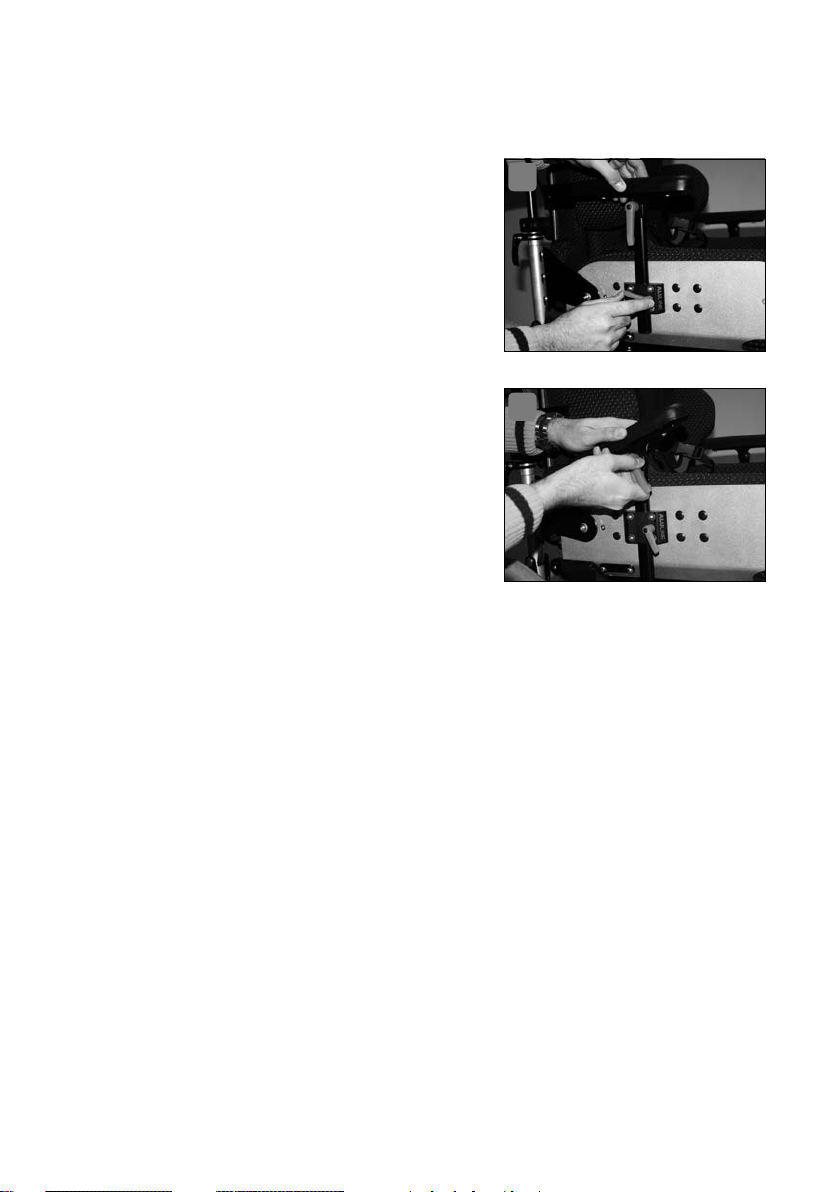
Alternativ zu den Standardsystemen zur
Armlagerung kann ERGOLINE mit unter
schiedlichen Armlehnen aus der Serie ALULINE ausgestattet werden� Befestigen Sie
die Armlehne, indem Sie den Feststellhebel an der Armlehnenaufnahme rechts und
links an den Seiten der Sitzschale lösen, die
Armlehnen einführen und den Feststellhebel
wieder anziehen� Zur Einstellung der Höhe
verändern Sie die Einstecktiefe im OvalrohrUnihalter (Bild 1)�
Zur Winkeleinstellung der Armlehne gehen
Sie wie folgt vor:
Öffnen Sie die Klemmung auf einer
Seiten des Armauflagenträgers durch
Drehen der Klemmhebel entgegen dem
Uhrzeigersinn (Bild 2)�
Die Armauflage ist nun in ihrer Winkelstellung zur Sitzschale beweglich�
Halten Sie die Armauflage in der gewünschten Stellung mit einer Hand fest
und drehen Sie mit der anderen Hand den Klemmhebel im Uhrzeigersinn
wieder zu�
Die Stellung der Armauflage bleibt nun erhalten�
Wiederholen Sie den Vorgang auf der anderen Seite�
1
-
2
5. Kopflagerung
Die Bauteile für die Kopflagerung werden über Universalhalter mit der harten
Außenschale verbunden� Eine Verstellung bedeutet immer, das eingesteckte
Vierkantrohr in seiner Einstecktiefe zu verändern�
Um dies durchzuführen gehen Sie wie folgt vor:
Drehen Sie den schwarzen Rändelknopf entgegen dem Uhrzeigersinn, bis
das eingesteckte Vierkantrohr sich frei verschieben läßt�
Verschieben Sie das Vierkantrohr bis in die gewünschte Position�
12 KOPFLAGERUNG
Page 13

Drehen Sie den schwarzen Rändelknopf im Uhrzeigersinn um das eingesteckte Vierkantrohr wieder festzuklemmen�
Wiederholen Sie den Vorgang auf der anderen Seite�
5.1 Kopfstützenhalter gekröpft
Mit dem gekröpften Kopfstützenhalter können Sie die Kopfstütze in zwei Ebenen
verstellen� Es sind dies die Höheneinstellung und die Tiefeneinstellung
Zur Höheneinstellung gehen Sie wie folgt vor:
Der Universalhalter für den Kopfstützenhalter befindet sich auf der Rückenseite der harten Außenschale� Zur Einstellung gehen Sie so vor, wie
unter Kap� 5� (Kopflagerung) beschrieben�
Zur Tiefeneinstellung gehen Sie wie folgt vor:
Lösen Sie die Klemmung am oberen Querrohr durch Drehen der Flügelschraube entgegen dem Uhrzeigersinn�
Verschieben Sie das Kopfstützenhalterohr im Querrohr bis die gewünschte
Position erreicht ist�
Fixieren Sie die Position durch Drehen der Flügelschraube im Uhrzeigersinn bis das Kopfstützenhalterohr sich nicht mehr verschieben läßt�
5.2 Kopfstützenhalter gerade
Mit dem gekröpften Kopfstützenhalter können Sie die Kopfstütze in zwei Ebenen verstellen� Es sind dies die Höheneinstellung und die Tiefeneinstellung� Die
Vorgehensweise ist die gleiche wie unter Kap 5�1 (Kopfstützenhalter gekröpft)
beschrieben�
Deutsch
5.3 Kopfstützenhalter Konusverstellung
Mit dem Kopfstützenhalter mit Konusverstellung können Sie die Kopfstütze in
zwei Ebenen verstellen� Es sind dies die Höheneinstellung und die Tiefeneinstellung über eine Winkelkonusverstellung�
Zur Höheneinstellung gehen Sie wie folgt vor:
Der Universalhalter für den Kopfstützenhalter befindet sich auf der Rückenseite der harten Außenschale� Zur Einstellung gehen Sie so vor, wie
unter Kap� 5 (Kopflagerung) beschrieben�
Zur Tiefeneinstellung gehen Sie wie folgt vor:
Öffnen Sie die Klemmung des Kopfstützenhalters durch Drehen der
schwarzen Klemmhebel entgegen dem Uhrzeigersinn�
KOPFLAGERUNG 13
Page 14

Der Kopfstützenhalter ist nun in seiner Winkelstellung zur Sitzschale beweglich�
Halten Sie die Kopfstütze in der gewünschten Stellung mit einer Hand fest
und drehen Sie mit der anderen Hand den schwarzen Klemmhebels im
Uhrzeigersinn wieder zu�
Die Stellung der Kopfstütze bleibt nun erhalten�
Jedoch ist es nun nötig das Kopfstützenpolster nachzustellen�
Drehen Sie nun die Kopfstütze in ihrem Befestigungspunkt wieder so, dass
der Kopf der in der Sitzschale sitzenden Person am jeweiligen Kopfstützenpolster anliegt�
5.4 Kopfstützenpolster
Für die Sitzschale ERGOLINE sind drei unterschiedlich geformte Kopfstützen
lieferbar, die über die oben beschriebenen Halterungen befestigt werden� Es
sind dies die Kopfstützenpolster:
Standard
Muschelform
Halbrolle
Die Kopfstützenpolster klettbar und Hinterhauptpolster werden nicht mittels der
Kopfstützenhalter montiert, sondern lediglich auf das Rückenpolster aufgeklettet�
5.4.1 Kopfstützenpolster Standard, Muschelform, Halbrolle
Diese Kopfstützenpolster sind über eine Verschraubung mit den Kopfstützenhalterungen gekröpft, gerade oder Konusverstellung verbunden� Die Grundeinstellung der Kopfstütze nehmen Sie bitte über die Halterungen vor�
5.4.2 Kopfstütze klettbar, Hinterhauptpolster
Die Kopfstütze klettbar oder das Hinterhauptpolster wird auf das Rückenpolster
aufgeklettet� Der Rücken der Sitzschale ist in diesem Fall soweit verlängert, dass
er über der Kopfhöhe des Patienten steht� Nur in diesem Fall sind die beiden
folgenden Kopfstützenvarianten montierbar�
Zur Montage eines der beiden Polster gehen Sie wie folgt vor:
Legen Sie das Kopfpolster mit der Rückseite (auf der das Hakenband aufgenäht ist) auf das Rückenpolster (auf der das Flauschband aufgenäht ist)
und drücken dieses leicht an� Die Stellung ist nun fixiert�
Zum Lösen des Polsters müssen Sie nur kräftig an dem Kopfpolster ziehen
um es vom Rückenpolster zu lösen�
14 KOPFLAGERUNG
Page 15
5.5 Kopfstützensysteme ALULINE
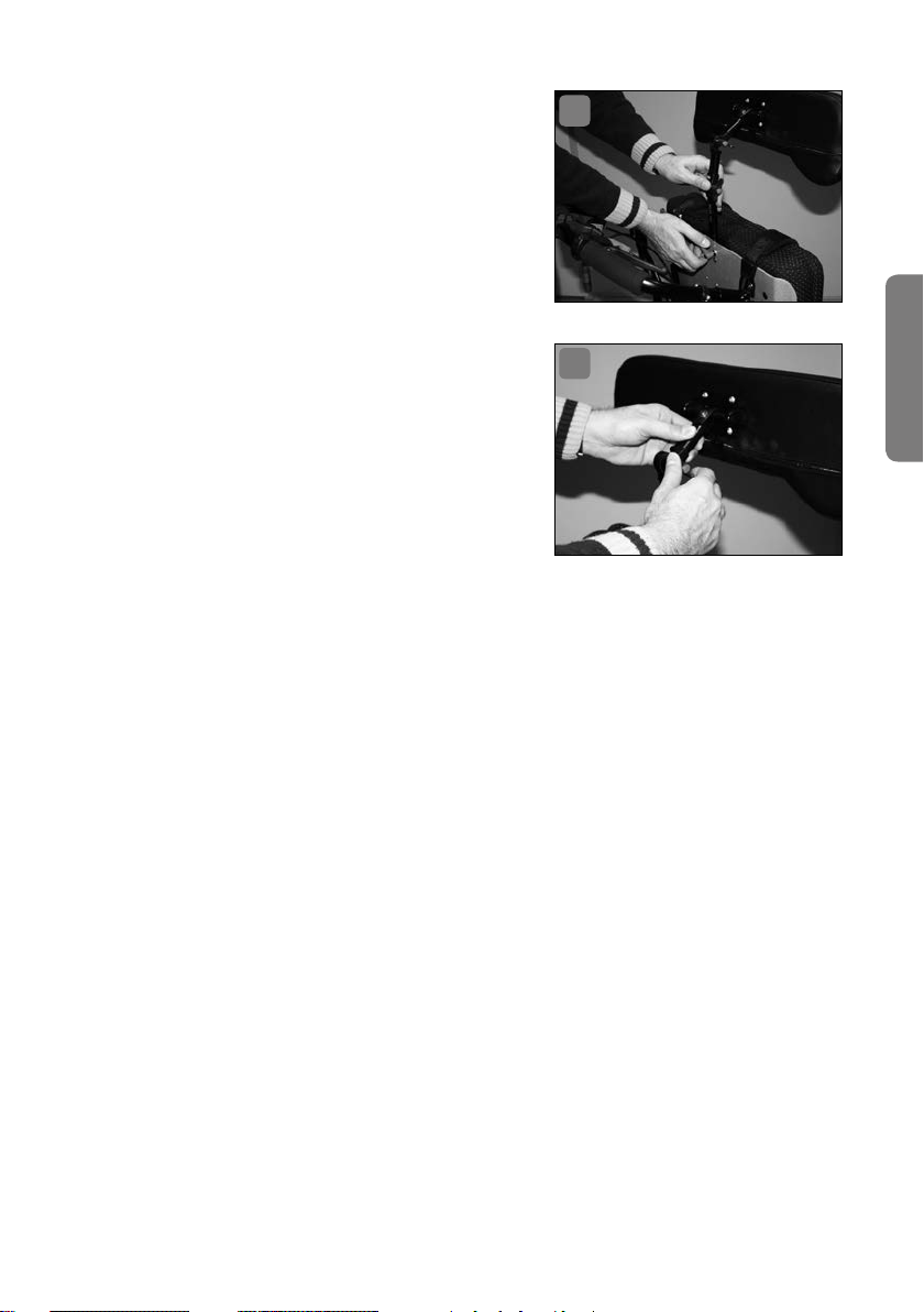
Alternativ zu den Standardsystemen zur
Kopflagerung kann ERGOLINE mit unter
schiedlichen Kopfstützensystemen der Serie ALULINE (gerade oder in Muschelform)
ausgestattet werden� Beide sind sowohl in
der Höhe als auch Tiefe einstellbar� Befestigen Sie die Kopfstütze, indem Sie den
Feststellhebel an der Kopfstützenaufnahme,
welche sich am oberen Teil der Rückenlehne
befindet, lösen, die Kopfstützenhalterung
einführen und den Hebel wieder anziehen�
Zur Einstellung der Höhe verändern Sie die
Einstecktiefe im Ovalrohr-Unihalter (Bild 3)�
Zur Tiefeneinstellung gehen Sie wie folgt vor:
Lösen Sie die Klemmung am oberen
Ovalrohr durch Drehen der Flügelschraube entgegen dem Uhrzeigersinn (Bild 4)�
Verschieben Sie das Kopfstützenhalterohr im Unihalter bis die gewünschte
Position erreicht ist�
Fixieren Sie die Position durch Drehen der Flügelschraube im Uhrzeigersinn bis das Kopfstützenhalterohr sich nicht mehr verschieben lässt�
3
-
4
Deutsch
6. Beinlagerung
Die Beinlagerung wird über verschiedenen Polster- und Begurtungselemente
gewährleistet�
6.1 Abduktionskeil (Spreizkeil)
Abduktionskeile gibt es für die ERGOLINE in drei Ausführungen: integriert, verstellbar und abschwenkbar�
6.1.1 Abduktionskeil integriert
Der integrierte Abduktionskeil wurde bei der Herstellung der Sitzschale in die
Sitzfläche integriert� Nachträglich können hier keine Einstellungen vorgenommen werden� Ist eine neue Anpassung notwendig, wenden Sie sich bitte an Ihr
Sanitätshaus�
BEINLAGERUNG 15
Page 16
6.1.2 Abduktionskeil verstellbar
Der verstellbare Abduktionskeil ist über eine Halterung mit der Sitzunterseite
der harten Sitzschalenaußenseite verbunden� Hier ist eine Einstellung möglich�
Die Einstellung bezieht sich darauf, wie weit der Abduktionskeil in die Sitzfläche
hineinragt� Ziel bei der Positionierung des Abduktionskeils ist, dass die Knie etwa
mittig der Abduktionskeilflanken zu liegen kommen�
Zur Einstellung des Abduktionskeils gehen Sie wie folgt vor:
Lösen Sie die Klemmung durch Drehen der Flügelschraube entgegen dem
Uhrzeigersinn� Die Flügelschraube befindet sich an der Unterseite der
Sitzfläche am dort montierten Halter für den Abduktionskeil�
Schieben Sie den Abduktionskeil in die richtige Position�
Fixieren Sie die Stellung durch Drehen der Flügelschraube im Uhrzeigersinn bis der Abduktionskeil nicht mehr verschiebbar ist�
6.1.3 Abduktionskeil abschwenkbar
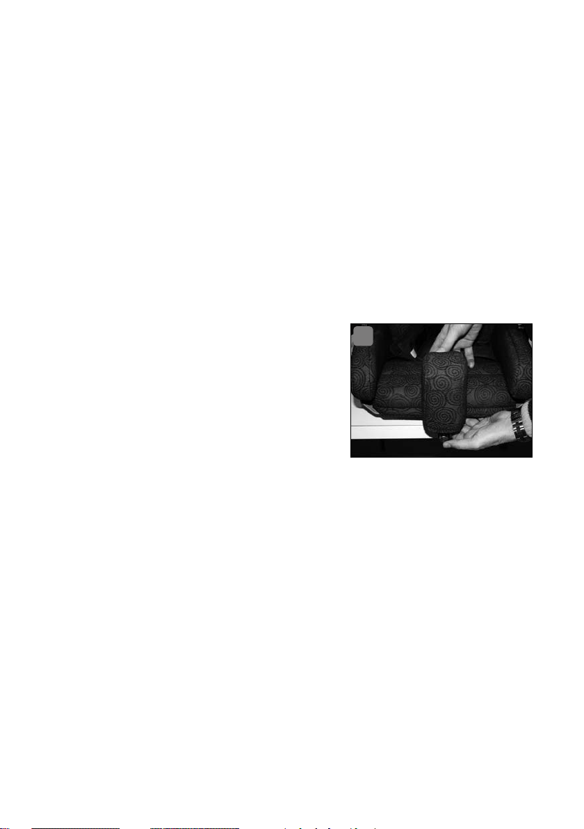
Der abschwenkbare Abduktionskeil ist eben-
5
falls über eine Halterung mit der Sitzunterseite
der harten Sitzschalenaußenseite verbunden�
Zum Einstellen gehen Sie vor wie beim verstellbaren Abduktionskeil (Kapitel 7�6�2)�
Zum Abschwenken des Abduktionskeils
gehen Sie wie folgt vor:
Lösen Sie die Arretierung, indem Sie den roten Knopf unterhalb des Abduktionskeils drücken (Bild 5)�
Nun lässt sich der Keil abschwenken�
Beim Zurückschwenken der Pelotten rastet die Arretierung hörbar ein und
fixiert so den Abduktionskeil�
6.2 Abduktionsgurt mit Steckschloss
Ein Abduktionsgurt fixiert die Oberschenkel am Oberschenkelpolster der Sitzschale�
Zum Anlegen des Abduktionsgurtes gehen Sie wie folgt vor:
Der eine Teil des Abduktionsgurtes kommt aus der Falte zwischen Sitzpolster und Oberschenkelposter und ist mit einem schwarzen Steckschlossschieber ausgestattet�
Das andere Teil des Abduktionsgurtes befindet sich außen an der Verschraubung des Oberschenkelpolsters und verfügt über die Steckschlossaufnahme�
16 BEINLAGERUNG
Page 17

Legen Sie den Teil des Abduktionsgurtes mit dem Steckschlossschieber
um den Oberschenkel der in der Sitzschale sitzenden Person und achten
Sie darauf, dass er nicht verdreht ist und flächig anliegt�
Stecken Sie den Steckschlossschieber in die Steckschlossaufnahme bis sie
hörbar einrastet�
Ggf� ändern Sie die Einstellung der Gurtlänge folgendermaßen: Sie ziehen
den Gurt enger, in dem Sie das freie Ende des Gurtbandes so lange von der
Kunststoffschnalle wegziehen, bis die gewünschte Spannung erreicht ist�
Sie lockern den Gurt in dem Sie das Gurtschloss senkrecht zum Gurtband
drehen und daran von der Sitzschale weg ziehen�
Stellen Sie die Gurtbandlänge so ein, das die Fixierung gewährleistet ist,
der Gurt aber nicht einschneidet�
6.3 Abduktionsgurt mit Umlenkrolle
Ein Abduktionsgurt fixiert die Oberschenkel am Oberschenkelpolster der Sitzschale�
Zum Anlegen des Abduktionsgurtes gehen Sie wie folgt vor:
Der eine Teil des Abduktionsgurtes kommt aus der Falte zwischen Sitzpolster und Oberschenkelposter und ist mit einer Umlenkrolle ausgestattet�
Das andere Teil des Abduktionsgurtes befindet sich außen an der Verschraubung des Oberschenkelpolsters und verfügt über aufgenähte KlettFlausch-Bänder
Legen Sie den Teil des Abduktionsgurtes mit der Umlenkrolle um den
Oberschenkel der in der Sitzschale sitzenden Person und achten Sie darauf, dass er nicht verdreht ist und flächig anliegt�
Stecken Sie das andere freie Ende (nicht zusammengeklettet) durch die
Umlenkrolle�
Ziehen Sie solange am freien Ende bis die gewünschte Einstellung erreicht
ist�
Legen Sie dann Klett- und Flauschteil aufeinander, die Einstellung ist nun
fixiert�
Stellen Sie die Gurtbandlänge so ein, das die Fixierung gewährleistet ist,
der Gurt aber nicht einschneidet�
Deutsch
BEINLAGERUNG 17
Page 18

7. Rumpffixierung
Verschiedene Optionen sind für die Sitzschale ERGOLINE möglich� Eine grundlegende Fixierung muss jede Sitzschale haben� Die Informationen finden Sie hierzu
unter Kap� 3�3 (Fixierung in der Sitzschale)� Weiterreichende Fixierungen sind in
den folgenden Unterkapiteln beschrieben�
7.1 Brustgurt mit Überschlaglasche
Der Brustgurt mit Überschlaglasche wurde bei der Anpassung der Sitzschale
in der richtigen Position montiert� Kleine Anpassungen in der Länge sind über
die Flausch-Klett-Verbindung möglich�
Zum Öffnen des Gurtes gehen Sie wie folgt vor:
Ziehen Sie die vordere Lasche von unten nach oben ab
Ziehen Sie nun die sich überlappenden Enden des Brustgurtes auseinander
Sie können nun die beiden Enden des Brustgurtes zur Seite legen und ggf�
die betreffende Person aus der Sitzschale nehmen�
Zur Fixierung in der Sitzschale gehen Sie beim Anlegen des Gurtes in umgekehrter Reihenfolge vor�
Achten Sie darauf, dass nach Anlegen des Gurtes nichts „eingeschnürt“
wird, insbesondere darauf, dass die Atmung nicht behindert wird�
7.2 Brustgurt mit Umlenkrolle
Der Brustgurt mit Umlenkrolle wurde bei der Anpassung der Sitzschale in der
richtigen Position montiert� Kleine Anpassungen in der Länge sind über die
Flausch-Klett-Verbindung möglich�
Zum Öffnen des Gurtes gehen Sie wie folgt vor:
Ziehen Sie die sich überlappenden Enden des Brustgurtes auseinander
Ziehen Sie das nun lose Ende des Brustgurtes durch die Metallschlaufe heraus
Sie können nun die beiden Enden des Brustgurtes zur Seite legen und ggf�
die betreffende Person aus der Sitzschale nehmen�
Zur Fixierung in der Sitzschale gehen Sie beim Anlegen des Gurtes in umgekehrter Reihenfolge vor�
7.3 Reklinationspelotten
Die Reklinationspelotten wurde bereits bei der Herstellung der Sitzschale in
die Rumpfpolster integriert� Die Einstellmöglichkeiten beziehen sich auf den
Abstand zwischen den beiden vorderen „Flügeln“, d� h� die Länge des verbindenden Gurtbandes�
18 RUMPFFIXIERUNG
Page 19

Voraussetzung: Die betreffende Person sitzt bereits in der Schale�
Zum Verschließen der Reklinationspelotten gehen Sie folgendermaßen vor:
Klappen Sie die beiden Reklinationspelotten nach vorne, so dass diese auf
dem Brustbein zu liegen kommen�
Öffnen Sie die Klappe des schwarzen Gurtspanners�
In den Schlitz zwischen beweglicher Klappe und feststehendem Teil schieben Sie nun das Gurtband�
Ziehen Sie das Gurtband bis die Polster locker auf dem Brustbein anliegen,
wenn die in der Sitzschale sitzende Person in aufrechter Stellung sitzt�
Halten Sie Gurtband und Reklinationspelotten in dieser Stellung fest�
Klappen Sie jetzt die Klappe des Gurtspanners zurück, so dass er im feststehenden Teil zu liegen kommt�
Das Gurtband ist nun fixiert�
Möchten Sie das Schloss öffnen, ziehen Sie die Klappe des Gurtspanners
nach oben und ziehen das Gurtband heraus� Sie können dann die beiden
„Flügel“ wegklappen um die in der Schale sitzende Person aus der Schale
zu heben�
7.4 Schulterbügel
Die Schulterbügel halten die Schultern an den Schalenrücken gedrückt�� Die
Schulterbügel wurden in ihrer Grundeinstellung bereits von dem Mitarbeiter
Ihres Sanitätshauses eingerichtet� Sollten hier eine Änderung der Einstellung
notwendig sein, so wenden Sie sich bitte an Ihr Sanitätshaus�
Deutsch
Zum Anlegen und Abnehmen der Schulterbügel gehen Sie bitte wie folgt vor:
Voraussetzung: Die betreffende Person sitzt in der Sitzschale�
Lösen Sie den schwarzen Hebel, der sich an der Verbindung des Schulterpolsterbügels zur eigentlichen Haltekonstruktion befindet durch Drehen
entgegen dem Uhrzeigersinn�
Der Schulterbügel ist nun verschieb- und drehbar
Führen Sie folgende Bewegungen durch indem Sie das gepolsterte Teil des
Schulterbügels mit einer Hand umfassen:
Ziehen Sie den Schulterbügel etwas vom Körper weg
Drehen Sie den Schulterbügel um 90° in eine waagere chte Position zum
Schalenrand
Schieben Sie den Schulterbügel nach hinten zum Schalenrücken hin
Wiederholen Sie den Vorgang auf der anderen Seite�
Die sitzende Person ist nun nicht mehr durch die Schulterbügel fixiert�
Zum Anlegen der Schulterbügel gehen Sie in umgekehrter Reihenfolge
RUMPFFIXIERUNG 19
Page 20

vor� Achten Sie darauf, dass nach dem Anlegen ein gleichmäßiger, nicht zu
fester Druck auf die Schultern ausgeübt wird�
7.5 Rumpfführungspelotten mit Abschwenkvorrichtung
Die Rumpfführungspelotten mit Abschwenkvorrichtung wurden bereits bei der
Herstellung der Sitzschale in die Rumpfpelotten integriert� Nachträglich können
hier an den Maßen der Polster keine Einstellungen mehr vorgenommen werden�
Ist eine neue Anpassung notwendig wenden Sie sich bitte an Ihr Sanitätshaus�
Zum Abschwenken der Rumpfführungspelotten gehen Sie wie folgt vor:
Fassen Sie mit einer Hand vorne am Polster�
Drücken Sie mit dem Zeigefinger der anderen Hand auf den geriffelten
Bereich des silberfarbenen Auslösehebels an der Außenseite des Abschwenkscharniers
Schwenken Sie das Rumpfpolster nun (während Sie den Auslösehebel gedrückt halten!) zur Seite weg�
Möchten Sie die Rumpfführungspelotten wieder in die Ausgangsstellung
zurückbringen, so schwenken Sie diese einfach zurück, bis sie hörbar einrastet�
7.6 Rumpfführungspelotten ohne Abschwenkvorrichtung
Die Rumpfführungspelotten ohne Abschwenkvorrichtung werden bereits bei der
Herstellung der Sitzschale in die Seitenteile des ERGOLINE-Rückens integriert�
Nachträglich können hier keine Einstellungen vorgenommen werden� Ist eine
neue Anpassung notwendig wenden Sie sich bitte an Ihr Sanitätshaus�
8. Rückenwinkelverstellung (optional)
Die Ihnen gelieferte ERGOLINE wurde mit der Option einer Rückenwinkelverstellung ausgerüstet� Bei der Verwendung dieser Option gibt es einige Punkte zu
beachten, um die sichere Verwendung der ERGOLINE zu gewährleisten�
Die folgenden Angaben beziehen sich auf die Montage der ERGOLINE auf ein
Untergestell Marke SIMPLY der Firma interco und muss bei Verwendung auf
anderen Untergestellen ggf� individuell auf die Anwendbarkeit überprüft werden�
Ausführung mit Rasterblechen für die Rückenwinkelverstellung:
1� Bedingt durch die Maximalneigung des Schiebegriffs des SIMPLY kann das
Rasterblech der Rückenverstellung der ERGOLINE bis max� zur vorletzten
20 RÜCKENWINKELVERSTELLUNG (OPTIONAL)
Page 21

Rasterung geneigt werden� Zu Ihrer Information sei jedoch erwähnt, dass
bereits die drittletzte Rasterstellung eine Rückenneigung von ca� 120° ermöglich, die im Regelfall ausreichen sollte � Möchten Sie eine größeren Winkel
ermöglichen, sollten Sie sich der Sitzneigungsverstellung am Untergestell
SIMPLY bedienen, um den Schwerpunkt der Produktkombination so tief wie
möglich zu halten�
2�
Die Kippschutzräder sind bei Nutzung der Rückenwinkelverstellung auf die
maximale Auszugsstufe einzustellen, da sonst im Zweifel kein zuverlässiger
Kippschutz gewährleistet ist� 3� Die Radstandsverlängerung für die Hinterachse
des SIMPLY muss auf den längstmöglichen Radstand ausgezogen werden�
4� Während der Einstellarbeiten an ERGOLINE oder SIMPLY darf sich der Patient
nicht in der Schale befinden�
Ausführung mit stufenloser Rückenwinkelverstellung:
1� Die stufenlose Rückenwinkelverstellung ermöglich eine Winkelöffnung von
ca� 120°�
2�
Bei der Einrichtung der Schale sind die gleichen Vorsichtmaßnahmen wie unter
den Punkten 1-4 (Ausführung mit Rasterblechen) beschrieben, einzuhalten�
Achtung: Sollten Sie Ihre ERGOLINE auf einem anderen Untergestell als dem
SIMPLY verwenden, weisen wir hiermit ausdrücklich darauf hin, dass dies auf
eigene Gefahr hin geschieht� Wir empfehlen daher dringend, mögliche Gefahren
wie ungünstige Beeinflussung von z� B� Kippsicherheit, Schwerpunktverlagerung,
Seitenstabilität, Beeinträchtigung von Bowdenzügen und Funktion der Bremsen,
etc� zu kontrollieren und im Zweifelsfall einen Fachhändler oder die Firma interco
zu Rate zu ziehen�
Deutsch
9. Reinigung
Alle unsere Bezugsstoffe sind bei 30° C waschbar� Wie Sie den Bezug abnehmen, wurde in Kap� 3�1�1 (Abnahme des Bezuges) beschrieben� Bitte
schauen Sie dort nach�
Benutzen Sie zur Wäsche ein Feinwaschmittel�
Trocknen Sie den Bezug nicht im Trockner!
Sollten Sie den Bezug der Sitzschale häufiger waschen wollen empfiehlt
sich ein zweiter Bezug, den Sie dann im Wechsel aufziehen können� Fragen
Sie hierzu in Ihrem Sanitätshaus nach�
Die Zusatzteile reinigen Sie bitte mit einer haushaltsüblichen milden Seifenlauge�
REINIGUNG 21
Page 22

10. Sicherheitshinweise
Bitte beachten Sie die folgenden Sicherheitshinweise:
Grundsätzlich ist die ERGOLINE- Sitzschale nicht dafür ausgelegt, in Verbindung
mit einem Untergestell aus dem Hause interco GmbH, oder in Verbindung mit
einem Untergestell eines anderen Herstellers, Patienten in der Schale sitzend,
- mit oder ohne Fixierung - , in Kraftfahrzeugen sowie in Behindertentransportfahrzeugen (BTW) zu transportieren� Von Seiten des Herstellers wird keine Haftung übernommen, falls es zu einem Personenschaden während eines solchen
Transportes kommt�
1� Die Sitzschale ist nur zum bestimmungsgemäßen Gebrauch bestimmt� Sie
dient der Lagerung und Fixierung von Personen mit entsprechenden Körpermerkmalen� Insbesondere fällt nicht unter den bestimmungsgemäßen
Gebrauch:
Die Benutzung der ERGOLINE durch andere Personen als Sitzmöbel,
die Verwendung der ERGOLINE als Autositz,
die Verwendung der ERGOLINE zur Stabilisierung bei der Körperpflege,
die Benutzung der ERGOLINE nach Demontage/Veränderung einzelner
Bauteile�
2� Die Sitzschale ERGOLINE ist zur Einlage in Standardfaltrollstühle konzipiert�
Die Fixierung und Begurtung wurde auf diesen Einsatzzweck hin ausgerichtet� Andere Nutzungen unterliegen daher nicht dem bestimmungsgemäßen
Gebrauch�
3�
Achten Sie immer darauf, dass die Schale fest mit dem Rollstuhl verbunden ist�
4� Montieren Sie kein Zubehör, dass nicht vom Hersteller geprüft und freigege-
ben wurde�
11. Wiedereinsatz und Entsorgung
Wiedereinsatz
ERGOLINE ist für einen Wiedereinsatz geeignet� Bevor
müssen alle notwendigen Reinigungs- und Wartungsarbeiten durchgeführt werden� Bei einer Weitergabe ist unbedingt darauf zu achten, alle für den Gebrauch
notwendigen Unterlagen (also auch diese Gebrauchsanweisung) mitzugeben�
Entsorgung
Wenn ERGOLINE ausgedient hat, erkundigen Sie sich bei Ihrem ortsansässigen
Entsorgungsunternehmen über die Entsorgungs- und Recyclingvorschriften�
22 SICHERHEITSHINWEISE
sie
weitergegeben wird,
Page 23
12. Konformitätserklärung
EG-Konformitätserklärung für Medizinprodukte
Name des Herstellers: interco GmbH
Gesellschaft zur Planung und Vertrieb von
Rehabilitationshilfen mbH
Adresse des Herstellers: Im Auel 50
53783 Eitorf
Wir erklären hiermit, dass das Produkt
Artikelbezeichnung: ERGOLINE Aktiv/Passiv Sitzschalensystem
Ausführung:
den einschlägigen Bestimmungen der nachstehenden Richtlinie entspricht:
Richtlinie 93/42/EWG über Medizinprodukte, Anhang I und VIII
Eitorf, den 24� November 2000
Michael Markwald
Geschäftsführer
Aluminium- oder Carbon-Leichtbauweise
Deutsch
KONFORMITÄTSERKLÄRUNG 23
Page 24

13. Serviceplan
Hinweis: Die Wartung sollte im Turnus von 6 Monaten erfolgen!
Pos. Bereich Prüfung
1 Funktions-
prüfung
2 Schraubver-
bindungen
3 Optik
(Sichtprüfung)
Einstellung /
Funktion
Rückenverstellung
Fixiereinheit
Armlehne
Kopfstütze
Abduktionskeil
Therapietisch
Schrauben
angezogen
Roststellen
Lack
Beflockung
Sauberkeit
Stoffnähte
(Lage /Aussehen)
Typenschild
in Ordnung Beschädigungen /
Verformungen
Austausch/
Ersatz
Page 25
Notizen
GARANTIEKARTE
Deutsch
Bei Einsendung dieser Karte gewähren wir auf Ihre ERGOLINE® eine erweiterte Garantie
von insgesamt 2 Jahren. Bitte füllen Sie diese Garantiekarte sorgfältig und vollständig
aus und senden Sie diese an uns zurück – vielen Dank.
Kostenträger/Krankenkasse:
Ort des Kostenträgers:
Seriennummer:
Lieferdatum:
Name des Patienten:
Straße:
PLZ/Ort:
Telefon*:
E-Mail*:
* freiwillige Angaben
Page 26
Notizen
ANTWORTKARTE
ABSENDER
Name
Straße
PLZ/Ort
Bitte
ausreichend
frankieren !
ANTWORT
interco GmbH
Im Auel 50
53783 Eitorf - Germany
Page 27

Contents
1. Introduction � � � � � � � � � � � � � � � � � � � � � � � � � � � � � � � � � � � � � � � � � � � � � � � � � � � 28
2. ERGOLINE seat shell and available accessories � � � � � � � � � � � � � � � � � � � � 28
3. ERGOLINE standard equipment � � � � � � � � � � � � � � � � � � � � � � � � � � � � � � � � � � 29
3.1 ERGOLINE seat shell with customized upholstery � � � � � � � � � � � � � � � � � � � 29
3.2 Using the seat shell � � � � � � � � � � � � � � � � � � � � � � � � � � � � � � � � � � � � � � � � � � � � 30
3.3 Restraints in the seat shell � � � � � � � � � � � � � � � � � � � � � � � � � � � � � � � � � � � � � � � 31
4. Arm positioning � � � � � � � � � � � � � � � � � � � � � � � � � � � � � � � � � � � � � � � � � � � � � � � 34
4.1 Arm rests, height-adjustable (standard arm upholstery) � � � � � � � � � � � � � 34
4.2
4.3 Arm cushion, trough-shaped � � � � � � � � � � � � � � � � � � � � � � � � � � � � � � � � � � � � � 35
4.4 Lower arm restraint � � � � � � � � � � � � � � � � � � � � � � � � � � � � � � � � � � � � � � � � � � � � 35
4.5 Arm rests ALULINE � � � � � � � � � � � � � � � � � � � � � � � � � � � � � � � � � � � � � � � � � � � � 35
5. Head positioning � � � � � � � � � � � � � � � � � � � � � � � � � � � � � � � � � � � � � � � � � � � � � � � 36
5.1 Head rest bracket, angled � � � � � � � � � � � � � � � � � � � � � � � � � � � � � � � � � � � � � � � 36
5.2 Head rest bracket, straight � � � � � � � � � � � � � � � � � � � � � � � � � � � � � � � � � � � � � � 37
5.3 Head rest bracket, continuous angle adjustment � � � � � � � � � � � � � � � � � � � � 37
5.4 Head rest cushion � � � � � � � � � � � � � � � � � � � � � � � � � � � � � � � � � � � � � � � � � � � � � � 37
5.5 Headrest systems ALULINE � � � � � � � � � � � � � � � � � � � � � � � � � � � � � � � � � � � � � 38
6. Leg positioning � � � � � � � � � � � � � � � � � � � � � � � � � � � � � � � � � � � � � � � � � � � � � � � � 39
6.1 Abduction pommel (spreading wedge) � � � � � � � � � � � � � � � � � � � � � � � � � � � � � 39
6.2 Abduction belt with push-in buckle � � � � � � � � � � � � � � � � � � � � � � � � � � � � � � � 40
6.3 Abduction belt with deflection roller � � � � � � � � � � � � � � � � � � � � � � � � � � � � � � 40
7. Lateral chest restraint � � � � � � � � � � � � � � � � � � � � � � � � � � � � � � � � � � � � � � � � � � 41
7.1 Chest belt with flap � � � � � � � � � � � � � � � � � � � � � � � � � � � � � � � � � � � � � � � � � � � � � � 41
7.2 Chest belt with deflection roller � � � � � � � � � � � � � � � � � � � � � � � � � � � � � � � � � � � 41
7.3 Reclining supports � � � � � � � � � � � � � � � � � � � � � � � � � � � � � � � � � � � � � � � � � � � � � � 41
7.4 Shoulder bands � � � � � � � � � � � � � � � � � � � � � � � � � � � � � � � � � � � � � � � � � � � � � � � � 42
7.5 Lateral side supports with swing-away unit � � � � � � � � � � � � � � � � � � � � � � � � 43
7.6 Lateral side supports without swing-away unit � � � � � � � � � � � � � � � � � � � � � 43
8. Back angle adjustment (optional) � � � � � � � � � � � � � � � � � � � � � � � � � � � � � � � � 43
9. Cleaning � � � � � � � � � � � � � � � � � � � � � � � � � � � � � � � � � � � � � � � � � � � � � � � � � � � � � � 44
10. Safety instructions � � � � � � � � � � � � � � � � � � � � � � � � � � � � � � � � � � � � � � � � � � � � � 44
11. Reuse and disposal � � � � � � � � � � � � � � � � � � � � � � � � � � � � � � � � � � � � � � � � � � � � 45
12. Declaration of conformity � � � � � � � � � � � � � � � � � � � � � � � � � � � � � � � � � � � � � � � 46
13. Service plan � � � � � � � � � � � � � � � � � � � � � � � � � � � � � � � � � � � � � � � � � � � � � � � � � � � 47
Arm rests, incrementally height- and angle-adjustable
(standard arm upholstery)
� � � � � � � � � � � � � � � � � � � � � � � � � � � � � � � � � � � � � � �
34
English
27
Page 28

1. Introduction
Congratulations on your purchase of a seat shell by interco!
This seat shell is a high-quality product� It has been manufactured and inspected
using the latest technology in cooperation with your medical supplies dealer�
We have provided a description of the individual components in these operating
guidelines in order to make it easier for you to handle the product� Please be
aware that these guidelines may include descriptions of components that are
not included in your product� It is important to adjust the product to meet the
needs of each individual patient� The list of accessories and their corresponding
descriptions is long in order to meet these many demands�
Please read the sections concerning your special model carefully and thoroughly
and keep these operating guidelines in a safe place so that you can refer to them
later, as needed� If you should have any questions about your seat shell, please
ask us or your qualified medical supplies dealer�
2. ERGOLINE seat shell and available accessories
The ERGOLINE seat shell is a seating aid suitable for insertion in a normal standard folding wheel chair� It is used to provide the patient with proper support
and positioning while seated in the wheel chair and can be adjusted to meet the
individual needs of each patient� The low overall height will not limit the patient’s
mobility and the wheel chair and all of its features will remain fully functional�
ERGOLINE essentially comprises two components, including:
ERGOLINE adapted seat unit
ERGOLINE adapted back unit
These two components are connected by means of hinges� However, the seat
and back can also be used individually� In addition, a variety of additional components, restraints, and aids can also be mounted to the seat shell� These individual components are described in the section dealing with the restraint of the
corresponding part of the patient’s body� Please see also the Table of Contents�
ERGOLINE is available in two versions:
ERGOLINE Aktiv (active seating system)
ERGOLINE Passiv (passive seating system)
28 INTRODUCTION
Page 29

Both versions are available in aluminium construction� ERGOLINE Aktiv is also
available in carbon lightweigt construction (ERGOLINE Carbon)�
3. ERGOLINE standard equipment
The ERGOLINE seat shell standard equipment includes several components
described in this separate section� Please see the Table of Contents for an exact
list� All of the other restraints and individual options are described in sections
4 through 7�
3.1 ERGOLINE seat shell with customized upholstery
The ERGOLINE seat shell is equipped and covered with customized upholstery�
You can wash this cover� Please see section 9 (Cleaning) for washing instructions�
The section below describes how to remove the cover�
3.1.1 Removing the cover
In order to be able to remove the cover, it is necessary to remove the hinges that
connect the seat unit and back unit, as well as any other components that are
bolted to the seat through the cover� If you are using the ERGOLINE seat or back
unit only, then it is not necessary to remove the hinges� You will need a crosstip
screwdriver in order to remove the hinges�
English
To do so, proceed as follows:
Turn the seat shell until the fastening screws are visible on the hinges�
Remove each screw by turning it counterclockwise� The seat and back
units are now separated�
Repeat these steps in reverse order to assemble the seat and back units�
To remove the covers, proceed as follows:
Open the zippers on the seat and back units and pull off each cover�
Please follow the instructions under section 9 (Cleaning) when washing the
covers�
Repeat these steps in reverse order to replace the covers�
3.1.2 Mounting the ERGOLINE seat shell to the wheel chair
The seat shell has been equipped with corresponding fastening straps for mounting it to the wheel chair� To mount it, proceed as follows:
Fold the ERGOLINE seat shell together as far as it will go, ensuring that the
seating and back surfaces are folded as tightly together as possible�
ERGOLINE STANDARD EQUIPMENT 29
Page 30

Open the hook and loop fastener on the back side of the ERGOLINE seat
shell� Secure the ERGOLINE seat shell to the seating surface on the wheel
chair using the hook and loop fasteners�
Secure the back of the ERGOLINE to the back frame on the wheel chair
using the two belts�
Place the ERGOLINE seat shell on the seating surface of the wheel chair,
ensuring that the back edge of the shell is flush against the back of the
wheel chair
Pull the hook and loop fasteners on the seat shell around the back frame of
the wheel chair and fasten them together, ensuring that they are as tight as
possible�
Then fold the back of the seat shell against the back frame and pull the
straps around the back frame�
Thread one end of the strap into the push-in buckle on the opposite strap
and pull the straps on the back of the seat shell around the back frame
of the wheel chair, ensuring that they are as tight as possible� Secure the
straps using the push-in buckle� The push-in buckle must click into place
with an audible “click” sound�
Repeat these steps in reverse order to remove the seat shell from the
wheel chair�
3.2 Using the seat shell
In order to place and secure the patient in the seat shell there are several basic
rules to follow� It is not possible to include all of the possible variations and special
cases in this brief section� If you have any doubts concerning how to handle the
seat shell, please ask your medical supplies dealer or speak with your therapist�
They are your best resource if you should experience any problems�
When placing the patient in the seat shell, please proceed carefully as follows:
Do not place the patient in the seat shell unless it has been properly
mounted to the wheel chair and is equipped with the necessary restraint
options�
Always check to ensure that the seat shell is securely connected to the
wheel chair� Please see section 3�1�2 (Mounting the ERGOLINE seat shell to
the wheel chair) to learn how to check this�
Check to ensure that all of the brakes on the wheel chair have been engaged� Please read the corresponding section in the operating guidelines
for your wheelchair to learn how to do so�
You can then place the patient in the seat shell� Please check to ensure
that all of the restraints (except for the pelvic harness) are out of the way
30 ERGOLINE STANDARD EQUIPMENT
Page 31

and that the patient is not sitting on them� In addition, check to ensure that
no hard objects are in the seat shell that could cause discomfort to the
patient�
The patient’s pelvis should be as far back in the seat shell as possible� This
is the only way to ensure optimal restraint and support�
Always work from the patient’s pelvis outwards when placing additional restraints� Do not proceed with positioning and restraining the torso and extremities, where applicable, until the pelvis has been optimally restrained�
3.3 Restraints in the seat shell
The options for restraining the patient’s body in the seat shell include:
Chest harness
Pelvic bands
Lap belt
Pelvic harness
Please see section 4 through 7 to learn about all of the other restraint and support options and how to operate them�
3.3.1 Chest harness
The chest harness is used to restrain the patient’s entire upper body� The 2 sections below describe how to secure the chest harness�
English
Important: Always adjust the chest harness, working from the hard back of the
shell outwards and using the 4 tighteners located there�
Restraining the patient in the seat shell
Preparation: Place the patient in the seat shell and lay the chest harness over
the back edge of the shell�
To restrain the patient, proceed as follows:
Lay the chest harness forward with each of the two shoulder straps on
either side of the patient’s head�
The lower end of the chest harness is equipped with two tighteners for
fastening the straps�
Open the flap on one of the black strap tighteners�
Take one of the straps that is sticking out between the seat cushion and the
back cushion and insert it into the corresponding slot between the moving
flap and the fixed part�
Pull the strap as far as it will go�
ERGOLINE STANDARD EQUIPMENT 31
Page 32

Hold the strap in this position�
Then close the flap on the tightener until it lies flat against the fixed part�
The strap is now secured�
To open the lock, pull on flap on the tightener and pull out the strap�
Repeat this procedure on the other side�
Repeat these steps in reverse order to release the chest harness�
Adjusting the chest harness
Preparation: Place the patient in the seat shell and apply the chest harness�
Important: Always adjust the chest harness, working from the hard back of the
shell outwards and using the 4 tighteners located there�
To adjust the chest harness, proceed as follows:
Adjust the lower ends of the chest harness first�
Open the lower tighteners on the hard back of the seat shell�
To do so, simply pull hard on the free end of the strap and the tightener will
open automatically�
Pull the strap on one side to the desired position�
Hold the strap in this position�
Then close the flap on the tightener until it lies flat against the fixed part�
Repeat this procedure to adjust the other side�
Repeat these steps to adjust the upper ends of the chest harness, using
the upper tighteners on the hard back of the seat shell� The procedure is
identical for both the upper and lower ends of the chest harness�
3.3.2 Pelvic band
Preparation: Place the patient in the seat shell and connect the pelvic band firmly
to the seat shell on one side�
Lay the pelvic band over the patient’s lap�
Then thread the free end of the strap into the clamping buckle while simultaneously pressing the pelvic band with one hand against the patient’s pelvis� Press on the moving part on the buckle using the thumb on the hand
that you are using to press the pelvic band and then thread the free end of
the strap into the buckle using your other hand�
Pull on the strap until the pelvic band has reached its final position� You
can verify this by checking to ensure that the band is positioned properly
and pressure is evenly distributed along the patient’s pelvis� The two large
cushions on the pelvic band should be centered on the two sides of the
patient’s pelvis to distribute pressure evenly�
32 ERGOLINE STANDARD EQUIPMENT
Page 33

To open the buckle, press on the moving part� This will release the strap
and you can then pull it out� Please make sure to hold the patient in place
in the seat shell when performing this step�
3.3.3 Lap belt with press buckle
Preparation: Place the patient in the seat shell�
Lay the lap belt over the patient’s lap with the inserter�
Press the inserter into the buckle while simultaneously pressing with one
hand against the patient’s pelvis�
Then pull on the free end of the strap until the lap belt has reached its final
position� You can verify this by checking to ensure that the belt is positioned
properly and pressure is evenly distributed along the patient’s pelvis�
To open the buckle, press hard on the red button in the middle of the
buckle� Please make sure to hold the patient in place in the seat shell when
performing this step�
Note: It is usually only necessary to adjust the belt once at the beginning� This
adjustment will be maintained even after you open the buckle� However, you must
check to ensure proper adjustment with each use�
3.3.4 Lap belt with deflection roller
Preparation: Place the patient in the seat shell�
Lay the part of the lap belt with the deflection roller over the patient’s lap�
Then pull on the other end of the belt using the deflection roller�
Then pull on the free end of the belt until the lap belt has reached its final
position� You can verify this by checking to ensure that the belt is positioned
properly and pressure is evenly distributed along the patient’s pelvis�
Secure it into position by connecting the free end of the belt with the hook
and loop fastener provided for this purpose�
To open the lap belt, release the hook and loop fastener�
English
Note: The belt must be adjusted with each use� Always check to ensure that the
belt is positioned properly each time you use it�
3.3.5 Pelvic harness
Preparation: Before placing the patient in the seat shell, always check to ensure
that the pelvic harness is sitting flat against the seating surface with no folds�
Then place the patient in the seat shell as described in section 3�2� (Using the
seat shell)�
ERGOLINE STANDARD EQUIPMENT 33
Page 34

Then, proceed as follows:
The pelvic harness is divided into two sections at the end toward the patient’s knees� The harness is equipped with one belt with a push-in buckle
for each leg�
Lay one of the belts from one side to the other over the patient’s thigh
and use one hand to press the press-in buckle inserter into the press-in
buckle� This receptacle is located at the corresponding edge of the seat
shell (right or left side, depending on which leg you are restraining)�
Repeat this procedure on the other side�
Check to ensure that the pelvic harness has been positioned properly� The
belt straps should support the patient’s pelvis without being too tight� The
harness should not have any folds or the like (risk of pressure areas!)
4. Arm positioning
The components for positioning the arms are connected to the hard outer shell
with universal brackets� Any adjustment involves changing the insertion depth
of the square tube�
To do so, proceed as follows:
Turn the black knurled knob counterclockwise until the square tube slides
easily�
Slide the square tube into the desired position�
Then turn the black knurled knob clockwise to resecure the square tube in
place�
Repeat this procedure on the other side�
4.1 Arm rests, height-adjustable (standard arm upholstery)
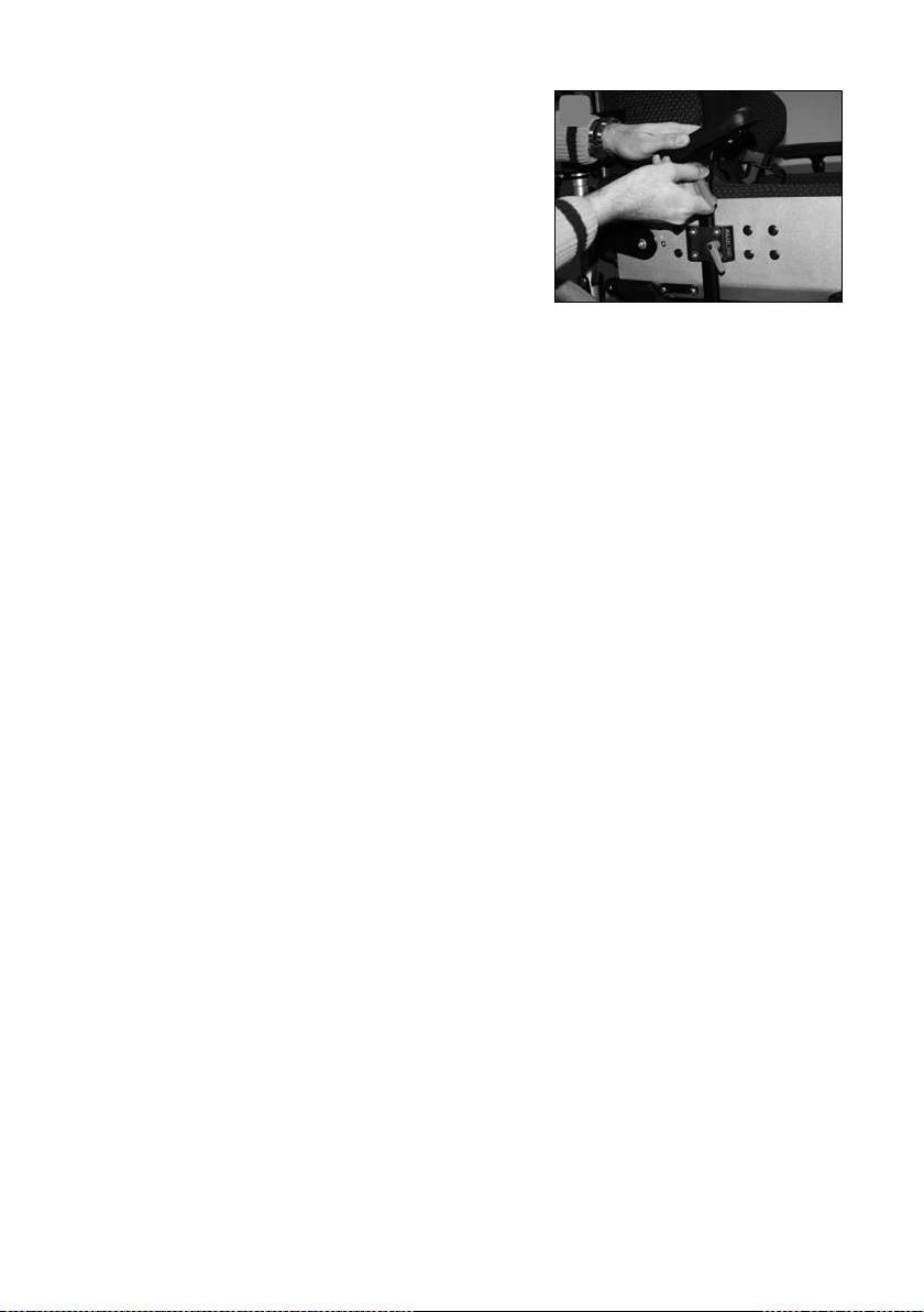
The height-adjustable arm rests are equipped with a standard cushion and secured to the seat shell with universal brackets� Please read section 4 (Arm positioning) to learn about the steps required to adjust the arm rest height�
4.2
Arm rests, incrementally height- and angle-adjustable (standard arm upholstery)
The height- and angle-adjustable arm rests are equipped with a standard cushion and secured to the seat shell with universal brackets� Please read section 4
(Arm positioning) to learn about the steps required to adjust the arm rest height�
34 ARM POSITIONING
Page 35
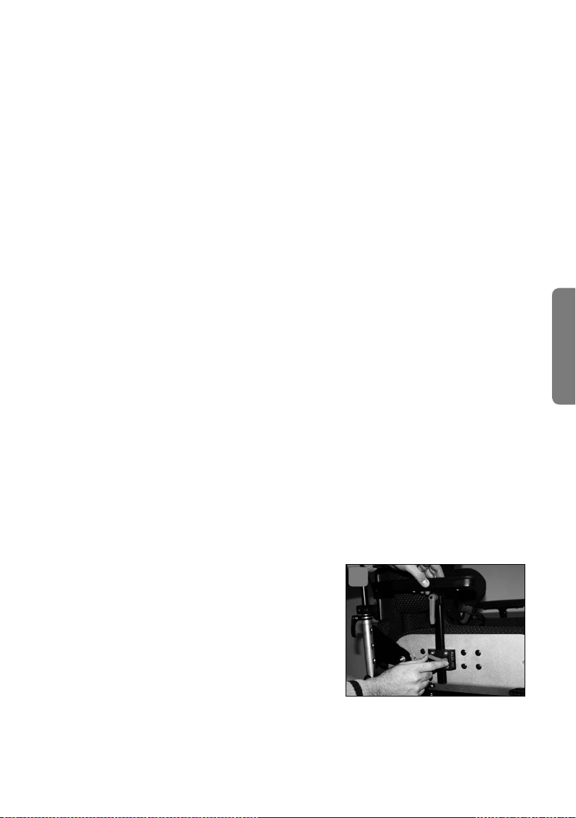
To adjust the angle, proceed as follows:
Turn the black lever counterclockwise to open the clamping unit on one
side of the arm rest bracket�
The angle of the arm rest to the seat shell can then be adjusted�
Hold the arm rest in the desired position with one hand and secure it in
place by tightening the black clamping lever with the other hand�
This will maintain the arm rest in position�
Repeat this procedure on the other side�
4.3 Arm cushion, trough-shaped
Trough-shaped cushions are used to replace standard arm cushions and have
a different shape that provides a sort of cushioned trough for the patient’s arm�
Read section 4�2 (Arm rests, incrementally height- and angle-adjustable (stand-
ard arm upholstery)) to learn how to adjust the height and angle�
4.4 Lower arm restraint
Lower arm restraints are used with trough-shaped arm cushions�
To restrain the lower arms, proceed as follows:
Fold the restraint straps away from the surface of the rest�
Place the patient’s lower arm on the trough-shaped arm cushion�
If necessary, adjust the height and angle of the arm rest, as described in
section 4�2 (Arm rests, incrementally height- and angle-adjustable (standard arm upholstery))�
Then use the hook and loop fasteners on the restraint straps to restrain
the arm without constricting it�
Repeat this final step with the second restraint strap�
Repeat this procedure on the other side, as needed�
English
4.5 Arm rests ALULINE
Alternatively to standard arm position-
1
ing systems ERGOLINE can be equipped
with different arm rests from the series
ALULINE� Fix the arm rest by loosening the
clamping lever of the arm rest receptacle
on the right and left side of the seat shell,
insert the arm rest holder and tighten the
lever again� Adjustments are always done
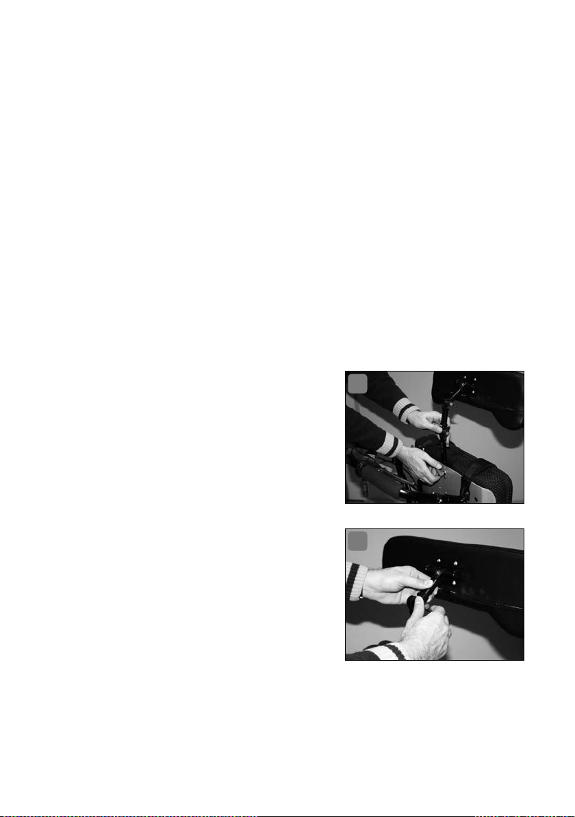
by changing the depth of the insertion in the square pipe (Photo 1)�
ARM POSITIONING 35
Page 36
To adjust the angle of the arm rest
proceed as follows:
Turn the fixing lever anticlockwise to
2
open the fixture (Photo 2)�
The arm rest angle now can be adjusted�
Change the square pipe to the desired
position and turn the black fixing lever
clockwise to fix the square pipe�
The position of the arm rest will now
stay the same�
Repeat the same procedure on the other side�
5. Head positioning
The components for positioning the head are connected to the hard outer shell
with universal brackets� Any adjustment involves changing the insertion depth
of the square tube�
To do so, proceed as follows:
Turn the black knurled knob counterclockwise until the square tube slides
easily�
Slide the square tube into the desired position�
Then turn the black knurled knob clockwise to resecure the square tube in
place�
Repeat this procedure on the other side�
5.1 Head rest bracket, angled
The angled head rest bracket can be used to adjust the head rest at two levels,
height and depth�
To adjust the height, proceed as follows:
The universal bracket for the head rest bracket is located on the back side
of the hard outer shell� To adjust it, proceed as described under section 5�
“Head positioning”�
To adjust the depth, proceed as follows:
Turn the wing screw counterclockwise to release the clamping device on
the top cross bar�
Slide the head rest bracket tube into the desired position in the cross bar�
36 HEAD POSITIONING
Page 37

Secure it into position by turning the wing screw clockwise until it is no
longer possible to slide the head rest bracket tube�
5.2 Head rest bracket, straight
The angled head rest bracket can be used to adjust the head rest at two levels,
height and depth� The procedure is identical to the one described under section
5�1 (Head rest bracket, angled)�
5.3 Head rest bracket, continuous angle adjustment
The head rest bracket with continuous angle adjustment can be used to adjust
the head rest at two levels, height and depth�
To adjust the height, proceed as follows:
The universal bracket for the head rest bracket is located on the back side
of the hard outer shell� To adjust it, proceed as described under section 5
(Head positioning)�
To adjust the depth, proceed as follows:
Turn the black clamping lever counterclockwise to open the clamping unit
on the arm rest bracket�
The angle of the head rest bracket to the seat shell can then be adjusted�
Hold the head rest in the desired position with one hand and secure it in
place by tightening the black clamping lever with the other hand�
This will maintain the head rest in position�
However, it is necessary to readjust the head rest cushion�
Turn the head rest at its fixation point until the patient’s head is positioned
comfortably on the head rest cushion�
5.4 Head rest cushion
There are three different head rests available for the ERGOLINE seat shell that
are secured using the bracket systems described above� The cushions available
for these head rests include:
Standard
Shell-shaped
Half-roll
The head rest cushions with hook and loop fasteners and cushions for the back
of the head are not mounted using head rest brackets, but are attached to the
back cushion with hook and loop fasteners�
English
HEAD POSITIONING 37
Page 38
5.4.1 Head rest cushions: Standard, shell-shaped, half-roll
These head rest cushions are bolted to the head rest bracket systems, including angled, straight or continuous angle adjustment� Please perform any basic
adjustments to the head rest using the bracket systems�
5.4.2 Head rest with Velcro attachment, cushion for back of the head
The head rests with Velcro attachment or the cushions for back of the head are
secured to the back cushion with hook and loop fasteners� In such cases, the back
of the seat shell is extended to a height above the patient’s head� These two head
rest versions are only able to be mounted with this type of seat shell configuration�
To mount one of these two cushions, proceed as follows:
Lay the back side of the head cushion (with the hook end of the fastener)
on the back cushion (with the loop end of the fastener) and press gently�
The cushion is now secured�
To remove the cushion, simply pull hard on the head cushion until it
releases from the back cushion�
5.5 Headrest systems ALULINE
Alternatively to standard headrest systems
ERGOLINE can be equipped with different
head rest systems from the series ALULINE
(straight or shell shaped)� Both are adjustable in height as well as depth� Fix the head
rest by loosening the clamping lever of the
head rest receptacle on the upper part of
the back rest, insert the head rest holder
and tighten the lever again� Adjustments are
always done by changing the depth of the
insertion in the square pipe (Photo 3)�
To adjust the depth proceed as follows:
Turn the fixing lever anticlockwise
until the square pipe can be moved
(Photo 4)�
Change the square pipe to the desired
position�
Turn the black fixing lever clockwise to fix the square pipe�
3
4
38 HEAD POSITIONING
Page 39

6. Leg positioning
Various cushions and straps are used to position the patient’s legs�
6.1 Abduction pommel (spreading wedge)
Three different abduction pommels are available for ERGOLINE: integrated, adjustable and swing-type�
6.1.1 Abduction pommel integrated
The integrated abduction pommel was affixed during manufacturing of the seat
shell� Adjustments can not be made after that� Should adjustments become necessary, please contact your specialist dealer�
6.1.2 Abduction pommel adjustable
The adjustable abduction pommel is affixed at the bottom of the outer side of the
hard seat shell� An adjustment is possible� The position of the pommel toward
the inner seat can be adjusted� It should be aimed that both knees are centered
toward the abduction pommel side�
To adjust the abduction pommel proceed as follows:
Loosen the clamp by turning the wing screw anticlockwise� The wing screw
is placed under the seat at the mounted holder of the abduction pommel�
Push the abduction pommel into the correct position�
Fix the position by turning the wing screw clockwise until the abduction
pommel can no longer be moved�
English
6.1.3 Abduction pommel swing-type
The swing-type pommel is also affixed at the bottom of the outer side of the hard
seat shell� For adjustments proceed like with the adjustable abduction pommel
(Chapter 7�6�2)�
To swing the abduction pommel forward
proceed as follows:
Loosen the catch by pressing the red
5
button underneath the absuction pommel (Photo 5)�
Now you can swing back the pommel�
To bring it back into its original position, move it back until it audibly locks�
LEG POSITIONING 39
Page 40

6.2 Abduction belt with push-in buckle
An abduction belt is used to restrain the thigh to the thigh cushion on the seat
shell�
To apply the abduction belt, proceed as follows:
One part of the abduction belt originates in the fold between the seat cushion
and the thigh cushion; it is equipped with a black press-in buckle inserter�
The other part of the abduction belt is located on the outside of the thigh
cushion bolt and is equipped with a push-in buckle receptacle�
Lay the part of the abduction belt with the push-in buckle inserter over the
patient’s thigh and check to ensure that it is lying flat and not twisted�
Insert the push-in buckle inserter into the push-in buckle receptacle until
it audibly clicks into place�
If it is necessary to readjust the belt length, proceed as follows: Pull the
belt tighter by pulling the free end of the belt strap away from the plastic
buckle until the desired tension is achieved� Loosen the belt by turning the
belt buckle until it is perpendicular to the belt strap and then pull it away
from the seat shell�
Adjust the belt strap length to ensure that it is secure but not constricting�
6.3 Abduction belt with deflection roller
An abduction belt is used to restrain the thigh to the thigh cushion on the seat
shell�
To apply the abduction belt, proceed as follows:
One part of the abduction belt originates in the fold between the seat cushion and the thigh cushion; it is equipped with a deflection roller�
The other part of the abduction belt is located on the outside of the thigh
cushion bolt and is equipped with a hook and loop fastener�
Lay the part of the abduction belt with the deflection roller over the patient’s thigh and check to ensure that it is lying flat and not twisted�
Then insert the other end of the belt (that is not fastened together) through
the deflection roller�
Pull the free end until the desired adjustment has been achieved�
Secure the hook and loop fastener; the adjustment is now secure�
Adjust the belt strap length to ensure that it is secure but not constricting�
40 LEG POSITIONING
Page 41

7. Lateral chest restraint
There are various options available for the ERGOLINE� Each seat shell must have
a basic restraint system� Please see section 3�3 (Restraints in the seat shell) for
more information� The sections below describe additional restraints�
7.1 Chest belt with flap
The chest belt with flap has been mounted in the proper position during adjustment of the seat shell� It is possible to perform minor adjustments to the length
using the hook and loop fastener�
To open the belt, proceed as follows:
Pull upwards on the front flap�
Then pull the overlapping ends of the chest belt apart�
You can then lay the two ends of the chest belt aside and remove the patient from the seat shell, as necessary�
Repeat these steps in reverse order when applying the belt to secure the
patient in the seat shell�
When applying the belt, check to ensure that it is not constricting the patient; this is especially important to ensure that the patient’s breathing is
not adversely affected�
7.2 Chest belt with deflection roller
The chest belt with deflection roller has been mounted in the proper position
during adjustment of the seat shell� It is possible to perform minor adjustments
to the length using the hook and loop fastener�
English
To open the belt, proceed as follows:
Pull the overlapping ends of the chest belt apart�
Pull the loose end of the chest belt through the metal loop�
You can then lay the two ends of the chest belt aside and remove the patient from the seat shell, as necessary�
Repeat these steps in reverse order when applying the belt to secure the
patient in the seat shell�
7.3 Reclining supports
The reclining supports have been built into the postural side supports during production of the seat shell� You can adjust them by adjusting the distance between
the two front “wings”, i�e� the length of the connecting belt strap�
LATERAL CHEST RESTRAINT 41
Page 42

Preparation: Place the patient in the seat shell�
To secure the reclining supports, proceed as follows:
Fold the two reclining supports forward and lay them on the patient’s
sternum�
Open the flap on the black strap tightener�
Insert the belt strap into the slot between the moving flap and the fixed part�
Pull the belt strap until the cushion lies loosely on the patient’s sternum
while the patient is seated upright in the seat shell�
Hold the strap and reclining supports in this position�
Then close the flap on the tightener until it lies flat against the fixed part�
The strap is now secured�
To open the lock, pull on flap on the tightener and pull out the strap� You
can then fold the two “wings” out of the way and remove the patient from
the seat shell�
7.4 Shoulder bands
The shoulder bands hold the shoulders against the back of the shell� The shoulder
bands have been set up during the basic adjustments performed by your medical
supplies dealer� If it is necessary to perform any readjustments, please contact
your medical supplies dealer�
To apply and remove the shoulder bands, proceed as follows:
Preparation: Place the patient in the seat shell�
Release the black lever located on the connection between the shoulder
cushion bar and the actual support structure by turning it counterclockwise�
It is then possible to slide and turn the shoulder band�
Perform the following movements by taking the upholstered part of the
shoulder band in one hand:
Pull the shoulder band away from the patient’s body somewhat
Turn the shoulder band 90° until it is horizontal with the edge of the seat�
Slide the shoulder band back toward the back of the shell�
Repeat this procedure on the other side�
The patient is then no longer restrained by the shoulder bands�
Repeat these steps in reverse order to apply the shoulder bands� When
applying the shoulder bands, check to ensure that pressure is evenly distributed on the shoulders and not excessive�
42 LATERAL CHEST RESTRAINT
Page 43

7.5 Lateral side supports with swing-away unit
The lateral side supports with swing-away unit have been built into the postural
supports during production of the seat shell� It is no longer possible to perform
any readjustments to the cushions� If it is necessary to perform any readjustments, please contact your medical supplies dealer�
To swing away the lateral side supports, proceed as follows:
Take hold of the front of the cushion with one hand�
Use your pointer finger on the other hand to press on the ribbed area of the
silver release lever on the outside of the swing-away unit hinge�
Then swing the postural side support away to the side (while still pressing
the release lever!)�
To return the lateral side supports back to their starting position, simply
swing them back into place until you hear an audible “click” sound�
7.6 Lateral side supports without swing-away unit
The lateral side supports without swing-away unit have been built into the side
elements of the ERGOLINE back unit during production of the seat shell� It is
not possible to perform any readjustments� If it is necessary to perform any
readjustments, please contact your medical supplies dealer�
8. Back angle adjustment (optional)
English
Your ERGOLINE has been equipped with a back angle adjustment option� There
are several rules to follow when using this option in order to ensure the safe use
of your ERGOLINE�
The information below relates to the mounting of the ERGOLINE on the SIMPLY
undercarriage manufactured by interco; the applicability of this information must
be checked when using the ERGOLINE with any other undercarriage�
Version with incremental adjustment plates for back angle adjustment:
1� The incremental adjustment plate on the ERGOLINE back angle adjustment
system is limited to the next-to-last adjustment level by the maximum inclination of the SIMPLY push bar� However, it should be mentioned here for your
information, that the third-to-last adjustment level enables the back unit to
be reclined to approx� 120°, which is usually sufficient� If you desire a greater
angle, then adjust the seat angle setting on the SIMPLY undercarriage in order
to maintain the lowest possible center of gravity for the product combination�
BACK ANGLE ADJUSTMENT (OPTIONAL) 43
Page 44

2� When using the back angle adjustment the anti-tipping wheels should be set
to maximum width; otherwise the anti-tipping function cannot be guaranteed�
3� The wheelbase extension for the rear axle of the SIMPLY must be adjusted to
the maximum wheelbase setting�
4� Never leave the patient in the seat shell while performing adjustments on the
ERGOLINE or the SIMPLY�
Version with continuous back angle adjustment:
1� Continuous back angle adjustment enables a maximum angle of approx� 120°�
2� The same precautions as those described under items 1-4 (Version with in-
cremental adjustment plates) must be taken when setting up the seat shell�
Important: If you use your ERGOLINE on any undercarriage other than the SIMPLY,
we hereby expressly inform you that you do so at your own risk� As a result, we urgently recommend that you check for negative impacts on anti-tipping safety, shifts
in the center of gravity, lateral stability, improperly functioning Bowden cables
and brakes, etc�; consult your qualified dealer or interco in the case of any doubts�
9. Cleaning
All of the fabrics for our covers are washable at 30 °C� Please see section
3�1�1 (Removing the cover) to learn how to remove the cover�
Use a detergent for delicate fabrics�
Never dry the covers in the dryer!
If you should wish to wash the seat shell cover frequently, then it is advisable to have an auxiliary cover to put on the seat shell while washing the
other cover� Ask about this at your medical supplies store�
Please clean additional parts with a mild household soap solution�
10. Safety instructions
Please observe the following safety instructions:
In principle, the ERGOLINE seat shell has not been designed for use with an undercarriage manufactured by interco GmbH or with an undercarriage by another
manufacture for the transport of patients while seated in the seat shell - with or
without restraints - in private cars or vehicles for transporting disabled persons�
The manufacturer shall assume no liability in the case of any personal damages
occurring during such transport�
44 CLEANING
Page 45

1� The seat shell is only approved for its intended use� It is used for positioning
and restraining persons with corresponding physical characteristics�
In particular, the intended use does NOT cover the following:
Use of the ERGOLINE as a seat by other persons,
Use of the ERGOLINE as a car seat,
Use of the ERGOLINE to stabilize the patient during performance of
personal hygiene,
Use of the ERGOLINE following disassembly/modification of individual
components�
2� The ERGOLINE seat shell is designed for insertion in standard folding wheel
chairs� The restraints and strap systems have been designed for this purpose�
As a result, other uses are not covered by the intended use�
3� Always check to ensure that the seat shell is securely connected to the wheel
chair�
4� Do not mount any accessories that have not been tested and approved by the
manufacturer�
11. Reuse and disposal
Reuse
ERGOLINE is suitable for reuse� Before it is passed on, all the necessary cleaning
and maintenance activities must be performed� When it is handed over, make
sure it is accompanied by all the documentation necessary for use (including
these instructions for use)�
English
Disposal
When ERGOLINE has reached the end of its ser vice life, make inquiries with your
local waste management company about the regulations concerning disposal
and recycling�
REUSE AND DISPOSAL 45
Page 46
12. Declaration of conformity
EU-Declaration of Conformity for Medical Devices
Name of the manufacturer: interco GmbH
Gesellschaft zur Planung und Vertrieb
von Rehabilitationshilfen mbH
Address of the manufacturer: Im Auel 50
53783 Eitorf GERMANY
We hereby declare that the device
Article description: ERGOLINE Aktiv/Passiv seat shell system
Version:
conforms to the pertinent provisions of the directive listed below:
Medical Device Directive 93/42/EEC, Annex I and VIII
Eitorf, 24 November 2000
Aluminium or carbon lightweight construction
Michael Markwald
CEO
46 DECLARATION OF CONFORMITY
Page 47

13. Service plan
Important: Inspections must take place every 6 months!
Pos. Area Check
Adjustment /
functionality
1 Function check
2 Screw
connections
3 Appearance
(visual inspection)
Back adjustment
Fixing unit
Arm rest
Head support
Abduction wedge
Therapy table
Screws tightened
Rust spots
Paintwork
Flock coating
Cleanliness
Fabric seams
(position / appearance)
Type plate
ok Damage /
deformation
Exchange /
replacement
English
SERVICE PLAN 47
Page 48

Notes
48 SERVICE PLAN
Page 49
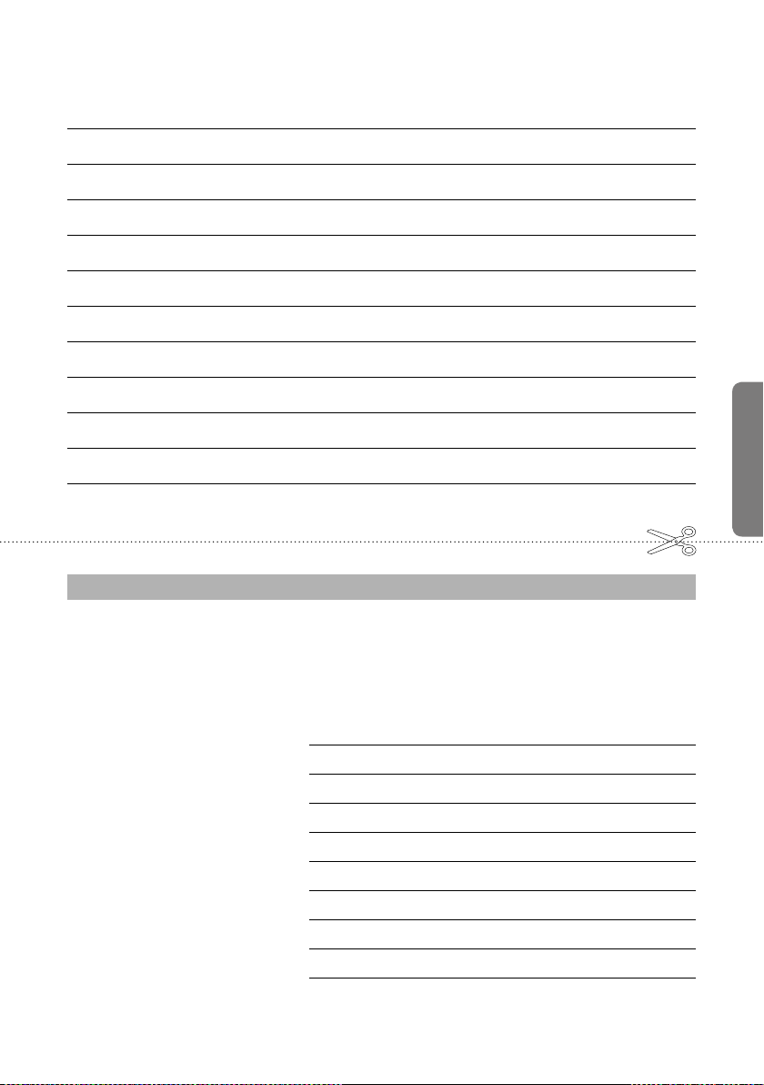
Notes
WARRANTY CARD
English
Upon submission in this card we will extend the warranty on your ERGOLINE® to cover
a total of 2 years. Please fill out this warranty card carefully and completely and return
it to us. Thank you very much.
Payer/Health Insurance Fund:
Location of the payer:
Serial number:
Delivery date:
Name of the patient:
Street:
Postal code/Place:
Telephone*:
Email*:
*Optional
Page 50
Notes
REPLY CARD
SENDER
Name
Street
Postal code/Place
Please be
sure to
include
sufficient
postage!
RETURN ADDRESS
interco GmbH
Im Auel 50
53783 Eitorf - Germany
Page 51

Page 52

Gesellschaft für Planung und Vertrieb
von Rehabilitationshilfen mbH
Im Auel 50
53783 Eitorf
Germany
T. +49 2243 8807-0
F. +49 2243 8807-29
E. info@interco-reha�de
I. www�interco-reha�de
© interco GmbH, Eitorf, 2018
Stand März 2018
Technische Änderungen vorbehalten
Status as per March 2018
Subject to technical alterations
without prior notification
Zertifiziert nach
Certified as per
DIN EN ISO 9001:2015
Reg�-Nr� 73 100 357-1
DIN EN ISO 13485:2012
Reg�-Nr� 70 105 357-1
TÜV Hessen
interc o und Seat up you r Life! sind ein getragene M arken der inter co GmbH · interc o and Seat up you r Life! are reg istered tr ademarks of i nterco GmbH
 Loading...