


www.intercel.com.au
USER
MANUAL
2
Feel free to contact Intercel’s dedicated technical support in case you need any assistance.
Intercel Pty Ltd.
Address
33 Glenvale Crescent, Mulgrave VIC 3170, Australia
Website
https://www.intercel.com.au
Email
intercel@intercel.com.au
Phone
+61 3 9239 2000
Fax Number
+61 3 9561 2614

3
Contact Information 2
Customer Support 2
Contact Us 2
Table of Contents 3
Table of Figures 5
Copyright and Permissions 6
Copyright © Intercel Pty Ltd. 2018. All rights reserved. 6
Trademarks and Permissions 6
Disclaimer 6
Section 1 - Introduction 7
1.1 - Overview 7
1.2 – Revision History 7
1.3 - Targeted Audience 7
1.4 - Notation 7
1.5 - Prerequisites 8
1.6 - Caution 8
Section 2 - Product Introduction 9
2.1 - Overview 9
2.2 - Package Content 9
2.3 - Specification 10
2.4 - Physical Dimensions and Indicators 11
2.4.1 - Physical Dimensions 11
2.4.2 - Front Panel 12
2.4.3 - Rear Panel 13
Section 3 - Configuration 14
3.1 - Basic Configuration 15
3.1.1 - Login 15
3.2 - Status 16
3.2.1 - Status - Basic Information 16
3.2.2 - Status - LAN 17
3.2.3 - Status - WLAN 18
3.2.4 - Status – Modem 19
3.2.5 - Status - Routing Table 20
3.3 - Network Configurations 21
3.3.1 - Network - LAN 21
3.3.2 - Network - Modem 22
3.3.3 - Network - Parameter Select 24
3.3.4 - Network - Network Type 26
3.3.5 - Network - DHCP Server 27
3.4 - Application Program Configuration 29
3.4.1 - Applications - ICMP check 29
3.4.2 - Applications - DDNS Configuration 30
3.4.3 - Applications - DTU Configuration 32
3.4.4 - Applications - MODBUS Configuration 35
3.4.5 - Applications - DIDO Configuration 37
3.4.6 - Applications - GPS Configuration 40
3.4.7 - Applications - SNMP Configuration 41
3.4.8 - Applications - M2M Configuration 42
3.4.9 - Applications - Timing Configuration 43
3.5 - VPN Configuration 44
3.5.1 - VPN - VPDN Configuration 44
3.5.2 - VPN - Tunnel Configuration 46
3.5.3 - VPN - IPSec Configuration 47

4
3.5.4 - VPN - Open VPN Configuration 51
3.6 - Forward Configuration 52
3.6.1 - Forward – NAT 52
3.6.2 - Forward - Routing 55
3.7 -QoS 57
3.8 - Dynamic Routing 58
3.9 - Security 60
3.9.1 - Security - IP Filter 60
3.9.2- Security - Domain Filter 62
3.9.3 - Security - MAC Filter 63
3.9.4 - Remote access 64
3.10 - System Configuration 65
3.10.1 - Local Log 65
3.10.2 - Remote Log 66
3.10.3 - Clock 67
3.10.4 - Account 68
3.10.5 - Network Test 69
3.10.6 – Files 70
3.11 - Reset Button Function 76
Section 4 - Typical Applications 77
4.1 - ICMP Detection Function Application 77
4.2 - DTU Function Applications 77
4.3 - Parameter Select 78
4.4 - VPN 78
4.5 - Timing Task 79
Section 5 - FAQ 80
5.1 - Hardware Issues 80
5.1.1 - All LED’s Blank 80
5.1.2 - SIM Slot 80
5.1.3 - Ethernet Connection 80
5.2 - Dialing Issues 81
5.2.1 - Dial Discontinue 81
5.2.2 - No Signal 81
5.2.3 - Cannot find SIM/USIM/UIM card 81
5.2.4 - Poor Signal 82
5.3 - VPN Problem 83
5.3.1 - VPDN cannot connect 83
5.3.2 - VPN cannot communicate 83
5.3.3 - Router can communicate but subnet cannot 83
5.4 – System Backup & Upgrade Issues 84
5.4.1 - Updating firmware failure 84
5.4.2 - Backup Setting problem 84
5.4.3 - Updating Patch Failure 84
5.4.4 - CFE Updating Failure 85
5.4.5 - Update Failure in Web GUI 85
5.4.6 - Forget Router Password 85
Section 6 - Abbreviations 86

5
Figure 1 3.1.1 Login .......................................................................................................................................................................... 15
Figure 2 3.2.1 Status – Basic Information.......................................................................................................................................... 16
Figure 3 3.2.2 Status - LAN ............................................................................................................................................................... 17
Figure 4 3.2.3 Status - WLAN ............................................................................................................................................................ 18
Figure 5 3.2.4 Status – Modem 2 ...................................................................................................................................................... 19
Figure 6 3.2.3 Status - Modem .......................................................................................................................................................... 19
Figure 7 3.3.3 Network - Parameter Select 1 .................................................................................................................................... 24
Figure 8 3.3.3 Network - Parameter Select 2 .................................................................................................................................... 24
Figure 9 3.3.4 Network - Network Type ............................................................................................................................................. 26
Figure 10 3.3.5 Network - DHCP Server ........................................................................................................................................... 27
Figure 11 3.4.1 Applications - ICMP Check 1 .................................................................................................................................... 29
Figure 12 3.4.1 Applications - ICMP Check 2 .................................................................................................................................... 29
Figure 13 3.4.2 Applications - DDNS Configuration 1 ....................................................................................................................... 30
Figure 14 3.4.3 Applications - DTU Configuration ............................................................................................................................. 32
Figure 15 3.4.4 Applications - MODBUS Configuration ..................................................................................................................... 35
Figure 16 3.4.6 Applications - GPS Configuration ............................................................................................................................. 40
Figure 17 3.4.7 Applications - M2M Configuration ............................................................................................................................. 42
Figure 18 3.4.9 Applications - Timing Configuration 1 ....................................................................................................................... 43
Figure 19 3.4.9 Applications - Timing Configuration 2 ....................................................................................................................... 43
Figure 20 3.5.1 VPN - VPDN Configuration 1 .................................................................................................................................... 44
Figure 21 3.5.1 VPN - VPDN Configuration ....................................................................................................................................... 44
Figure 22 3.5.2 VPN - Tunnel Configuration ...................................................................................................................................... 46
Figure 23 3.5.3 VPN - IPSec Configuration 1 .................................................................................................................................... 47
Figure 24 3.5.3 VPN - IPSec Configuration 2 .................................................................................................................................... 47
Figure 25 3.5.3 VPN - IPSec Configuration 3 .................................................................................................................................... 49
Figure 26 3.5.3 VPN - IPSec Configuration 4 .................................................................................................................................... 50
Figure 27 3.5.4 VPN - Open VPN Configuration ............................................................................................................................... 51
Figure 28 3.6.1 Forward Configuration 1 ........................................................................................................................................... 52
Figure 29 3.6.1 Forward Configuration 2 ........................................................................................................................................... 52
Figure 30 3.6.1 SNAT Configuration rule .......................................................................................................................................... 53
Figure 31 3.6.1 MSAQ 2 .................................................................................................................................................................... 54
Figure 32 3.6.2 Forward - Routing ..................................................................................................................................................... 55
Figure 33 3.9.1 Security - IP Filter 1 .................................................................................................................................................. 60
Figure 34 3.9.1 Security - IP Filter 2 .................................................................................................................................................. 61
Figure 35 3.9.2 Security - IP Filter 3 .................................................................................................................................................. 61
Figure 36 3.9.2 Security - Domain Filter 1 ......................................................................................................................................... 62
Figure 37 3.9.2 Security - Domain Filter 2 ......................................................................................................................................... 62
Figure 38 3.9.3 Security - MAC Filter ................................................................................................................................................ 63
Figure 39 3.9.4 Security - MAC Filter ................................................................................................................................................ 64
Figure 40 3.10.1 Local Log ................................................................................................................................................................ 65
Figure 41 3.10.2 Remote Log ............................................................................................................................................................ 66
Figure 42 3.10.3 Clock ...................................................................................................................................................................... 67
Figure 43 3.10.4 Account .................................................................................................................................................................. 68
Figure 44 3.10.5 Network Test .......................................................................................................................................................... 69
Figure 45 3.10.6 Firmware setting ..................................................................................................................................................... 70
Figure 46 3.10.6.2 CFE mode Upgrading .......................................................................................................................................... 71
Figure 47 3.10.6.2 CFE mode Upgrading 2 ....................................................................................................................................... 71
Figure 48 3.10.6.3 USB Upgrade ...................................................................................................................................................... 72
Figure 49 3.10.6.4 Backup Setting .................................................................................................................................................... 73
Figure 50 3.10.6.5 Factory setting ..................................................................................................................................................... 74
Figure 51 3.10.6.6 Patch Operation function ..................................................................................................................................... 74
Figure 52 3.10.6.7 Reboot/Refresh ................................................................................................................................................... 75

6
All information in this user manual is protected by copyright law. No organisation or individual shall copy or reproduce
the whole or part of this user manual by any means, without written permission from Intercel Pty Ltd.
Intercel, Intercel logo, and Ultra eSAM are the trademarks of Intercel Pty Ltd. All other trademarks and logos
mentioned in this document are the property of their respective holder. Intercel Pty Ltd does not own the rights to
these other trademarks and logos.
The contents of this document are subject to change without notice, due to continued progress in methodology, design
and manufacturing. Intercel shall have no liability for any error or damage of any kind resulting from the use of this
document.
7
Ultra eSAM is a data communication terminal built on the mobile communication network and independently
developed by Intercel. The product is based on 3G/4G wireless communication technology. It uses a high
performance 32-bit embedded operating system and has a robust industrial design. It can provide high-performance
3G/4G communication speed by accessing the 3G/4G network via the embedded 4G module. It is widely used in
various industries such as telecommunication, finance, information media, electric power, transportation, onboard
devices and environmental protection. This manual provides information related to the installation, operation and
application of Ultra eSAM device.
If you find the product damaged or malfunctioning, please contact technical support for service through email at
https://www.intercel.com.au/contact/.
For product updates, manual revisions, or software upgrades, please visit our website at https://www.intercel.com.au/.
This document is targeted towards:
• R&D Engineers
• Technical Support Engineers
• End Users
The symbols that may be found in this document are defined as follows:
Symbol
Description
Indicates a potentially hazardous situation, which if not
avoided, could result in equipment damage, data loss or
performance degradation.
Indicates a tip that may help you address a problem or save
your time.
Provides additional information to emphasise or
supplement important points of the main text.
Revision
Date
Description
1.0
April 20, 2018
Initial revision.
TABLE 1 REVISION

8
Before continuing with the installation of your Ultra eSAM, please make sure that you have the following:
1. A device with a working Ethernet network adapter.
2. A web browser such as Internet Explorer, Mozilla Firefox or Google Chrome.
3. A flathead screwdriver, if using RS232 or GPIO port via terminal block and a Philips head screwdriver to
mount a din-rail clip on the router.
Due to the nature of wireless communications, transmission and reception of data can never be guaranteed. Data may
be delayed, corrupted (i.e. have errors) or be totally lost. Although significant delays or loss of data are rare when
wireless devices are used in a conventional manner on a well-constructed network, the router should not be used in
situations where failure to transmit or receive data could result in damage of any kind to the user or any other party,
including but not limited to personal injury, death, or loss of property. Intercel accepts no responsibility for damages of
any kind resulting from delays or errors in data transmitted or received using the router, or for a failure of the router to
transmit or receive such data.
The router generates radio frequency (RF) power. When using the router, care must be taken on safety issues
related to RF interference as well as regulations of RF equipment.
Do not use your router in places where using cellular products are prohibited.
Be sure that the router will not be interfering with nearby equipment, such as pacemakers or medical
equipment. The antenna of the router should be away from computers, office equipment, home appliances etc
An external antenna must be connected to the router for proper operation. Only use approved antenna with
the router. Please contact Intercel for an approved antenna.
Always keep the antenna with a minimum safety distance of 25 cm or more from the human body. Do not put
the antenna inside any metallic box, container etc.
Check for any regulation or law authorizing the use of cellular devices in a vehicle in your country before
installing the router in a vehicle.
Installation should only be performed by qualified personnel. Consult your vehicle distributor for any possible
interference between electronic parts and the router.
The router should be connected to the vehicle’s supply system using a fuse-protected terminal in the vehicle’s
fuse box.
Do not expose the router to extreme conditions such as high humidity/rain, high temperature, direct sunlight,
caustic/harsh chemicals, dust or water.
Do not try to disassemble or modify the router.
Do not drop, hit or shake the router. Do not use the router under extreme vibrating conditions.
Do not pull the antenna or power supply cable. Attach/detach by holding the connector. .
This product should be operated only from the type of power source indicated on the product label.
Do not operate this product near/under water.
Do not place or operate this product near or over a radiator or heat register.
Do not expose this product to dampness, dust or corrosive liquids.
This product should not be carried by hand during operation.
This product should work in a good ventilation environment. Insufficient airflow may harm the product.
Unplug the product from the power supply when cleaning or assembly changing.
IIf a problem occurs, please contact Intercel technical support.
9
Ultra eSAM is a robust 4G Router for Industrial M2M/IoT applications. It has 1 LAN and 1 LAN/WAN to provide realtime data connectivity, even in harsh environments. Ultra eSAM provides a secure, reliable connection to industrial
machines on third-party sites or remote locations. The device incorporates flexible mounting options, wide input
voltage range and a wide operating temperature range. Ultra eSAM also allows remote system monitoring, remote
diagnostics, remote configuration and firmware updates over the air. Featuring Ethernet, Serial (RS232/422/485), and
USB 2.0 connectivity, the Ultra eSAM router can interface with a diverse range of equipment used in a wide variety of
vertical applications. Ultra eSAM also features built-in GPS and input & output ports, making it ideal for a broad range
of industrial applications. It supports Modbus data transmission, IO, SMS alarm and M2M cloud platform alarm,
amongst other features.
Intercel Ultra eSAM router assembly kit consists of the following items:
1 x Ultra eSAM Router
2 x Cellular Antennas
1 x Wi-Fi Antenna
1 x GPS Antenna
1 x 5-PIN Terminal Block
1 x Ethernet Cable
1 x Din-Rail Clip
2 x Phillips-head Screw for Din-Rail Clip
1 x 12 VDC Power Supply
10
CPU & STORAGE
• Powerful 580Mhz CPU
• 1Gb DDR2 SDRAM
• 128Mb Flash memory
ETHERNET INTERFACE
• 1 x LAN (10/100Mbps)
• 1 x LAN (10/100Mbps) / WAN Support (ADSL) PPPoE,
Static IP, DHCP client
• IEEE 802.3, IEEE 802.3u standard
• 1.5KV magnetic isolation protection
ANTENNA CONNECTORS
• 2 x SMA-K connectors for 3G/4G
• 1 x SMA-K connector for 2.4G wireless LAN
• 1 x SMA-K connector for GPS
USB PORT
• 1 x USB Type A
• USB 2.0 standard
SERIAL PORT
• 1 x RS232/RS485/RS422 interface
• Serial via terminal block with RX, TX, and GND
• 15KV ESD protection
I/O PORT
• 2 X I/O interfaces
• GPIO via terminal block
SYSTEM
• Reset Button
• LED indicators for Power, Network connectivity, Network
Signal and Wi-Fi
• 1 x Standard SIM/R-UIM with push-Button-to-release
Lockable Tray and 15KV ESD protection
WI-FI
• IEEE 802.11b/g/n standard
• 300Mbps data speed
• 2.412 - 2.485 GHz frequency band support
• AP, Client, Bridge mode
• WEP, WPA, WPA2 encryption
NETWORK & ROUTING
• Static, Policy route
• Port Forwarding
• RIP (V1/v2)/OSPF/BGP route
• Dynamic DNS
FIREWALL & FILTER
• IP packet/Domain/MAC filter
• SNAT
• DNAT
• DMZ
VPN
• IPSec
• PPTP/L2TP client
• GRE/IPIP
• DMVPN
• OpenVPN
DEVICE MANAGEMENT
• Local or Remote Web Browser HTTP
• CLI/Telnet command line
• Intercel’s Remote Cloud Management Platform
• SSH
REMOTE CLOUD MANAGEMENT
• View Online/Offline status of a device
• Remote terminal management and maintenance
• Check the status of internet data consumed at a specific
date
• Device location via GPS
• Debug remotely
• Flow statics and data analysis
POWER SUPPLY & CONSUMPTION
• 1 x 4-pin Micro fit connector
• Wide range 9 - 30 VDC input voltage
• Power Consumption:
Idle: 40mA@+12VDC
Communications: 240mA@+12VDC
11
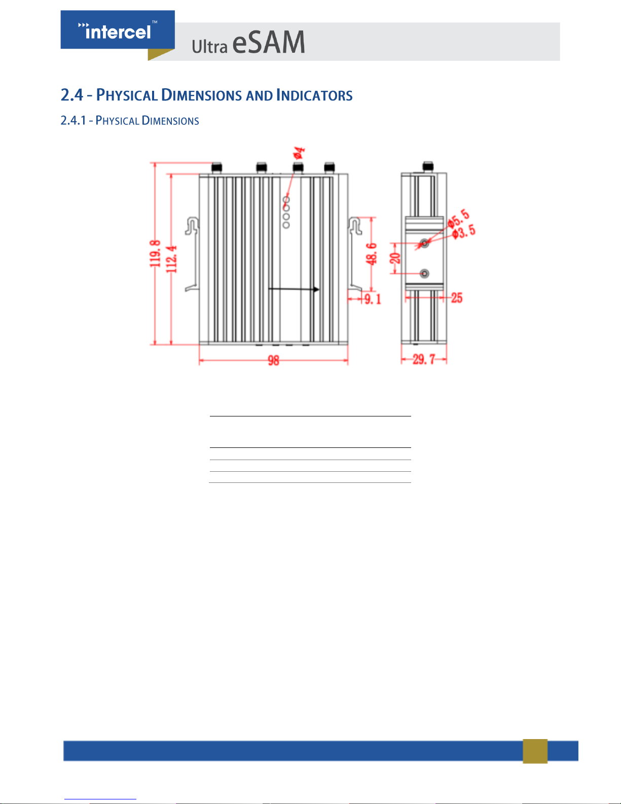
Diagram 1 – Physical Dimension
.
Ultra eSAM Router
(Without External Antennas Attached)
Length
112.4 mm
Width
98 mm
Height
29.7 mm
TABLE 2 1.4 DIMENSIONS

12
Diagram 2 - Front Panel
Below is the list of front panel interfaces:
• 4 x antenna interfaces (SMA-K female connector)
• 1 x SIM card slot (1.8V/3.0V)
• 1 x RESET button
• 1 x USB Connection
13
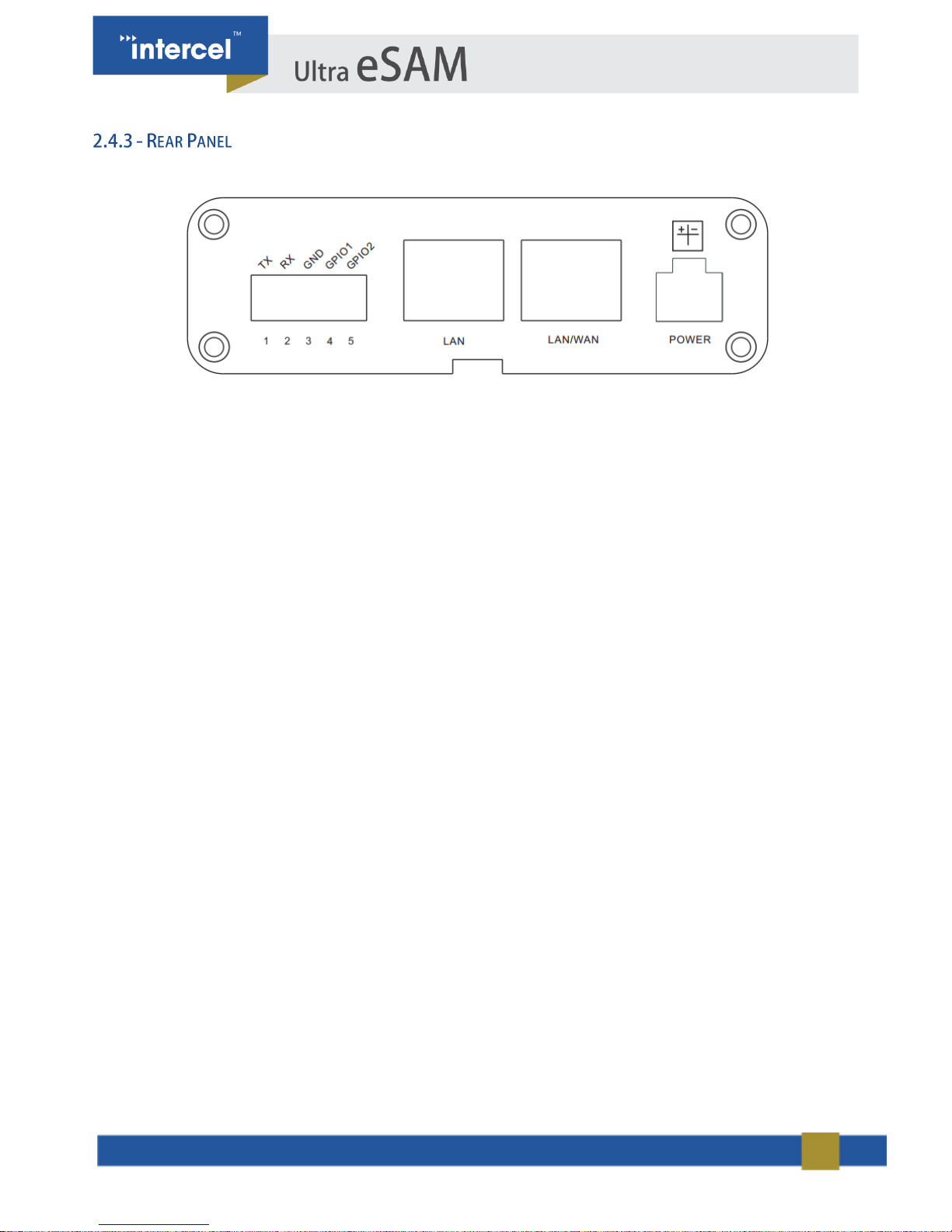
Diagram 3 – Rear Panel
Below is the list of rear panel interfaces:
• 1 x 5-PIN terminal block interface (RS232 serial port & GPIO)
• 2 x LAN interfaces
• 1 x 4-Pin micro fit power interface
14
Ultra eSAM can be configured via a web interface. You will need to connect your computer to the Ultra eSAM using an
Ethernet cable to access this interface.
The Web interface can be accessed using your web browser at IP address 192.168.8.1
To connect your computer to the Ultra eSAM, you must ensure that your Computer is assigned a valid IP address.
This IP Address must be assigned either:
Automatically from the Ultra eSAM modem (DHCP), or
Manually, by setting the IP address to 192.168.8.X where X is from 2 to 253.
Suggested Web Browser for the configuration of the Ultra eSAM are either Internet Explorer 8.0 or later, or Mozilla
Firefox 22.0 or later.
Open a web browser, power on the module, wait until the IP address of the PC is connected to the Ultra eSAM
modem. Now, type in the address bar 192.168.8.1, which is the default IP address of the modem. You will be
forwarded to the login page for entering Username and Password. By default, the Username and Password are both
"admin". They should be changed through the web interface later.
15
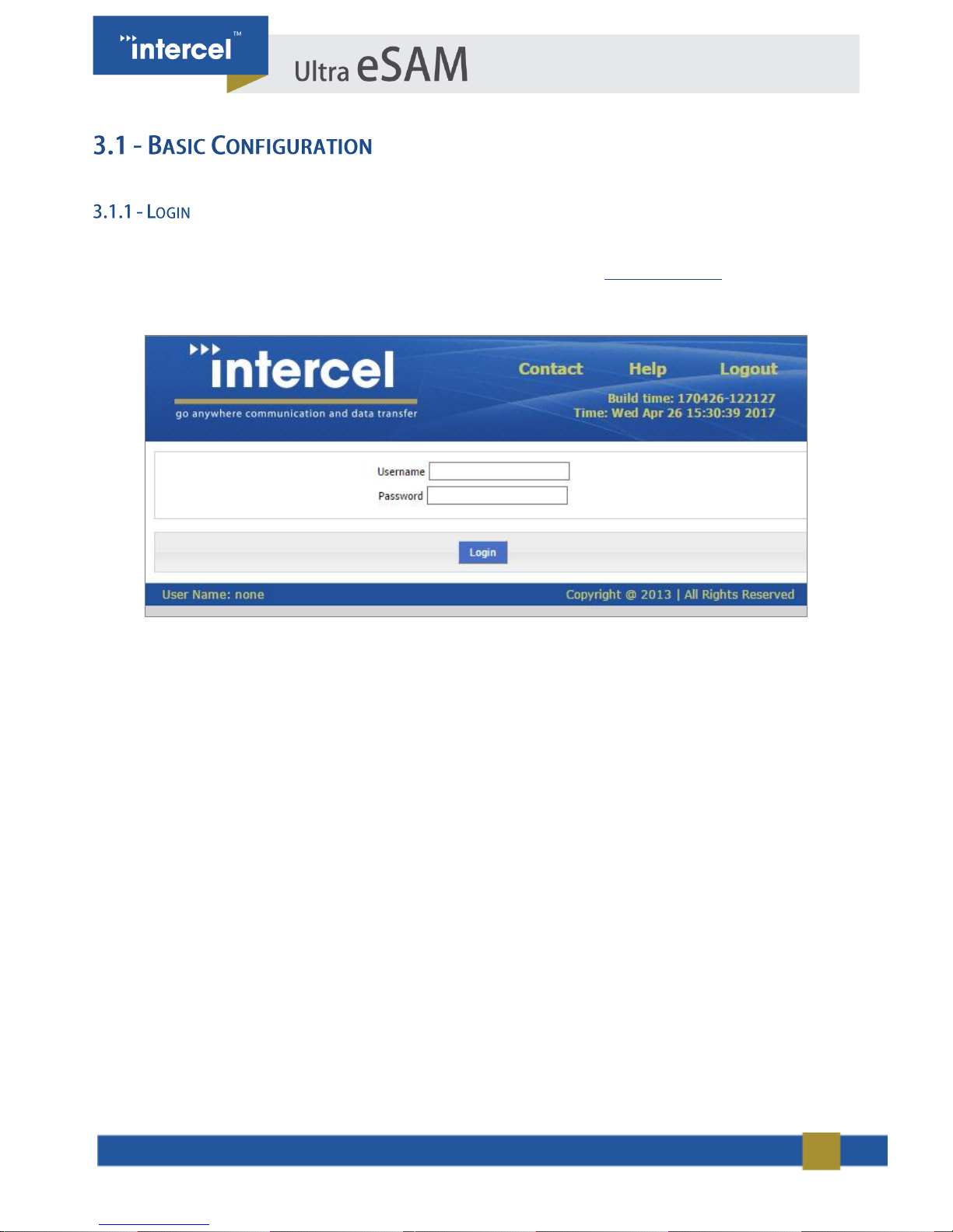
To access the eSAM Configuration, open your web browser and go to the link “http://192.168.8.1/”. The default
Username and Password should be “admin”.
FIGURE 1 3.1.1 LOGIN
16
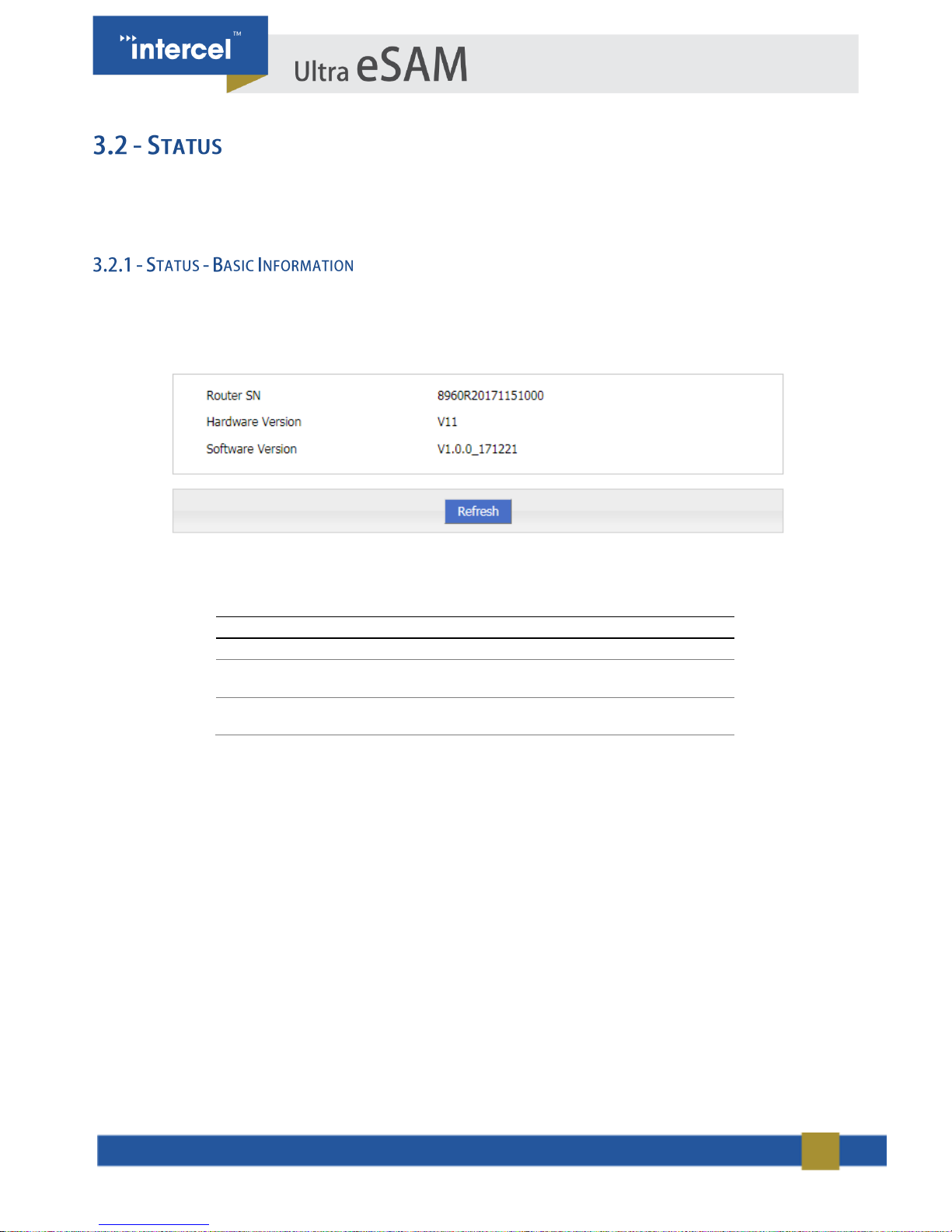
Status provides basic information such as network status and settings of the Ultra eSAM.
Login to the web interface of Ultra eSAM.
Click “Status > Basic information”. The “Basic Information” tab will automatically appear.
FIGURE 2 3.2.1 STATUS – BASIC INFORMATION
PARAMETER
DETAILS
Router SN
Router Serial, No information
Hardware version
Router hardware version
information
Software version
OS and application software
information
TABLE 3 3.2.1 STATUS - BASIC INFORMATION
17
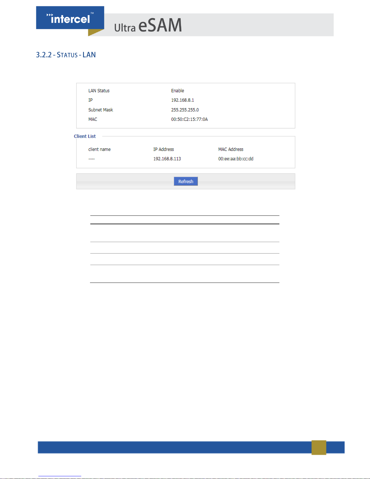
Click “Status > LAN” to open “LAN” tab.
FIGURE 3 3.2.2 STATUS - LAN
PARAMETER
DETAILS
LAN status
LAN connectivity – either
Enabled or Disabled
IP address
Show the IP address
Subnet Mask
Displays Subnet mask
MAC address
Shows the mac address of the
router
TABLE 4 STATUS - LAN
18
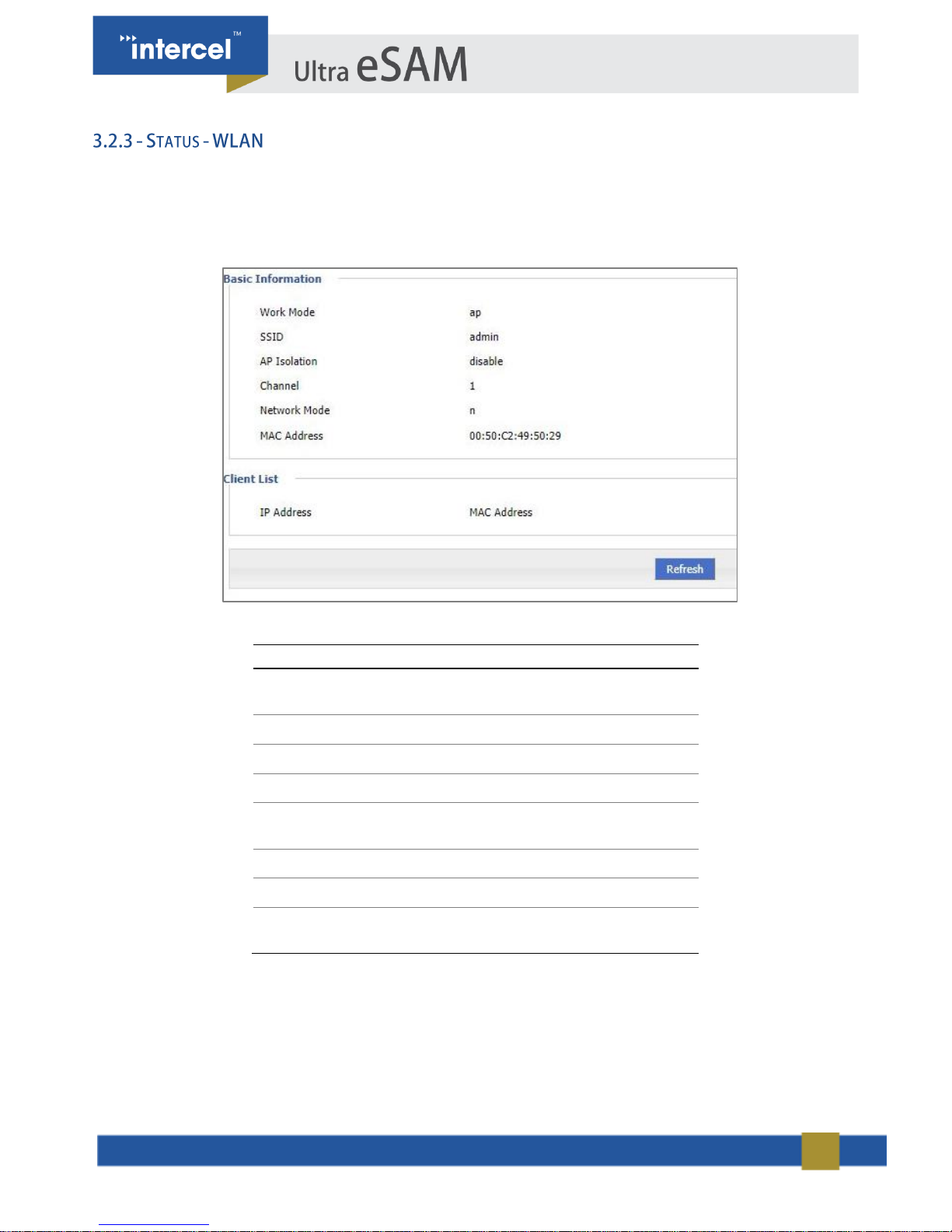
Status of WLAN will show If you are connected via Wi-Fi or not, as well as some details on your Wi-Fi status.
Click the “Status > WLAN" to open “WLAN” tab.
PARAMETER
DETAILS
Work Mode
Shows the WLAN mode:
AP/Station/Repeater
SSID
Displays identification of AP
AP Isolation
Displays the AP Isolation
Channel
Displays AP working channel
Network Mode
The network mode is used by the
current AP.
MAC Address
The physical address of a device.
IP Address
The IP address of the WLAN client.
MAC Address
The physical address of the WLAN
client.
TABLE 6 3.2.5 STATUS - WLAN
FIGURE 4 3.2.3 STATUS - WLAN
19
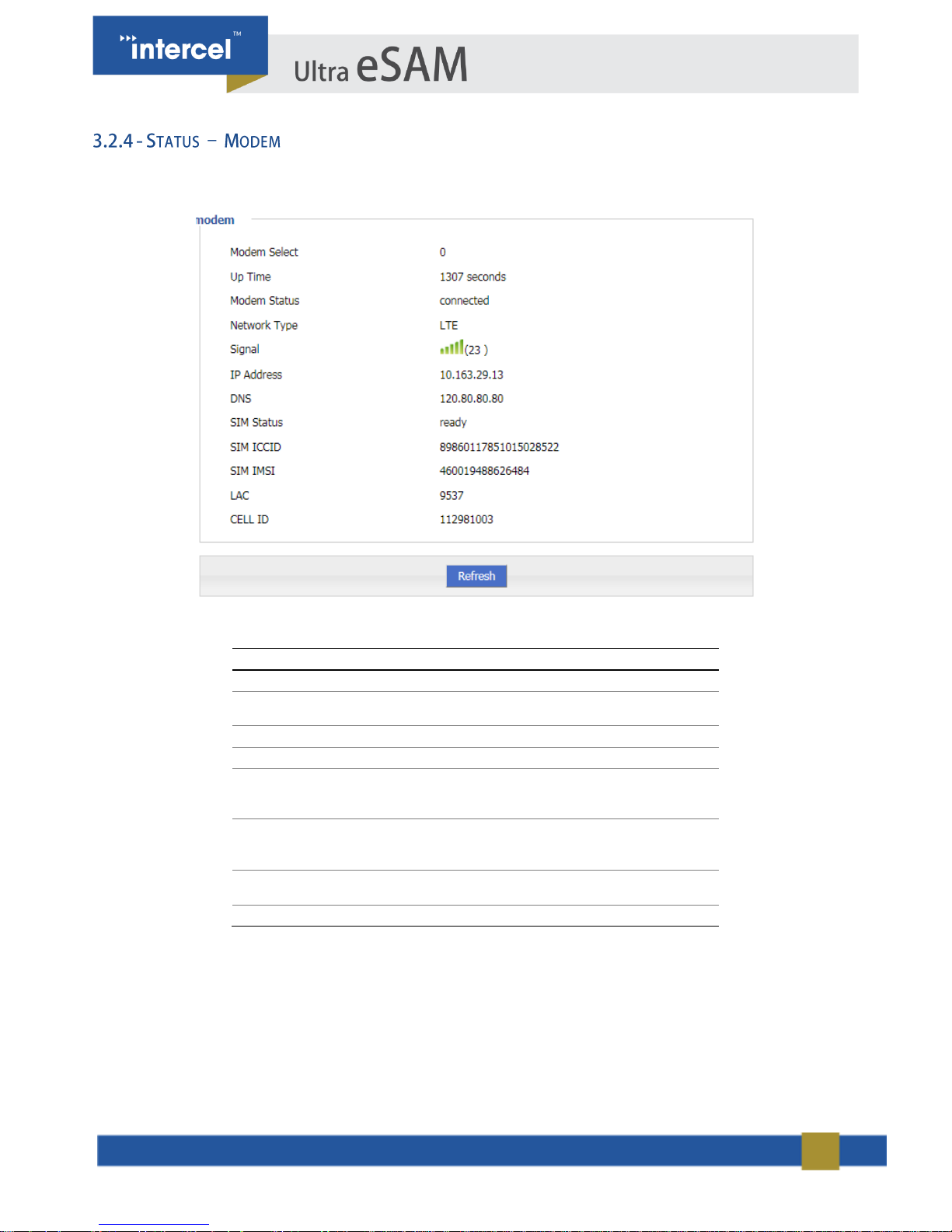
Click “Status > Modem” to open “Modem” tab.
FIGURE 5 3.2.4 STATUS – MODEM 2
PARAMETER
DETAILS
Modem Select
Displays the modem name
Up Time
Displays the uptime of the Modem
Modem Status
Displays router’s mobile connectivity
Network type
Type of the current network.
Signal
Signal Strength of the mobile network
Range: 1-31
IP Address
Displays the external network IP
address assigned by mobile network
DNS
Displays DNS assigned by mobile
network
SIM Status
Status of the current SIM
FIGURE 6 3.2.3 STATUS - MODEM
20
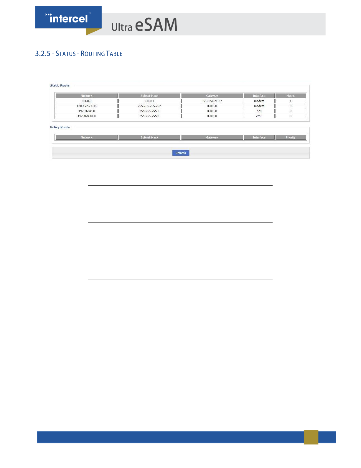
Click ‘Status’ > ‘Routing Table’ to open “Routing Table” tab.
FIGURE 6 3.2.5 STATUS – MODEM 1
PARAMETER
DETAILS
Network
IP address the router can reach
Subnet Mask
IP network the router can reach. It is used
together with “Network”
Gateway
Next hop IP address which the router will
reach
Interface
Interface from router to gateway
Metric
Route No which the router reaches
destination IP
Priority
Priority the router select route
TABLE 7 3.2.4 STATUS - ROUTING TABLE
21
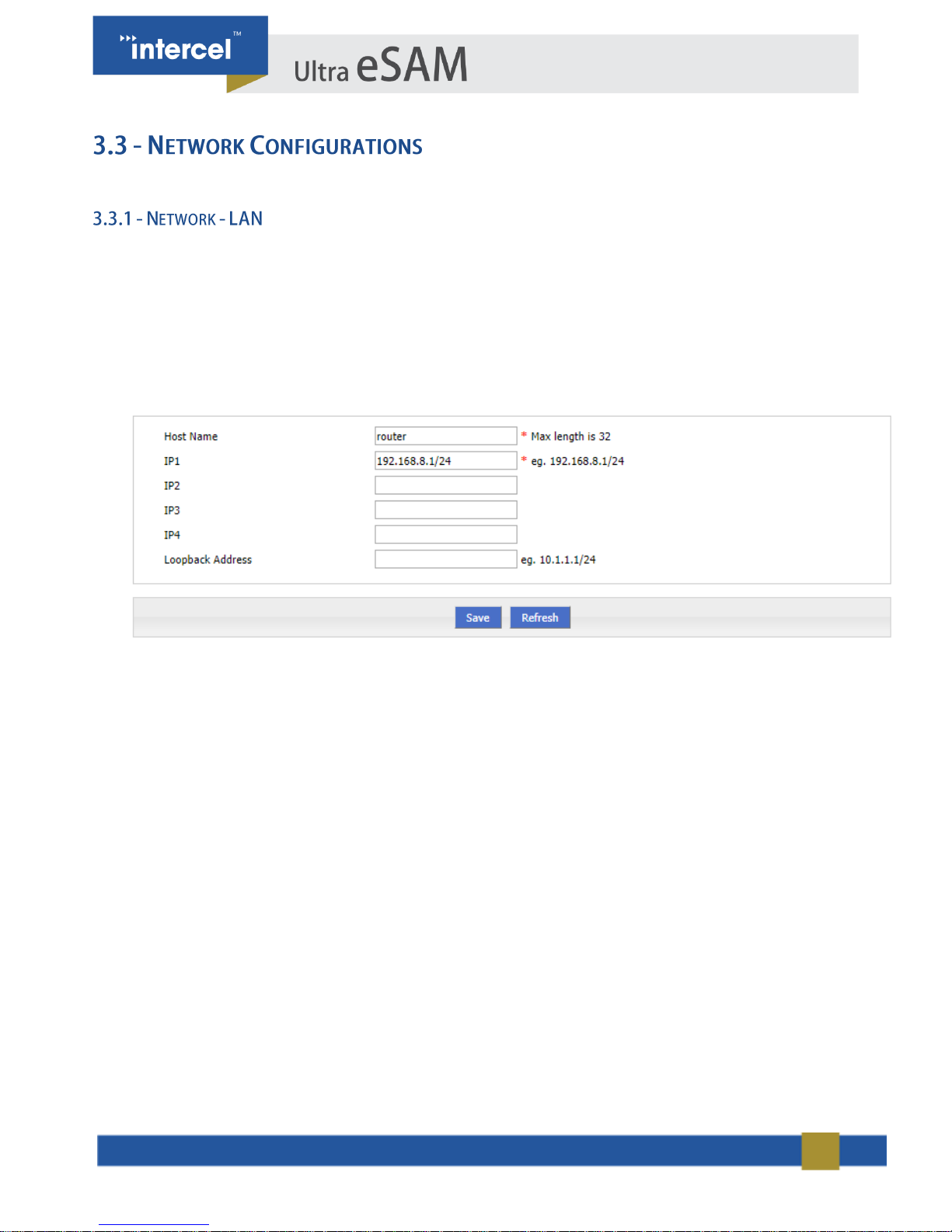
You can set the parameters of LAN.
1. Single click “Network > LAN”. The “LAN” tab will automatically appear.
2. Enter desired LAN parameters.
3. Single click “Save”, to save settings.
4. After changing the LAN IP, if the web page doesn’t respond anymore, please makes sure your PC address is on
the same network segment. You can set a new IP on your PC to ensure that.
FIGURE 8 3.3.2 NETWORK – MODEM
22
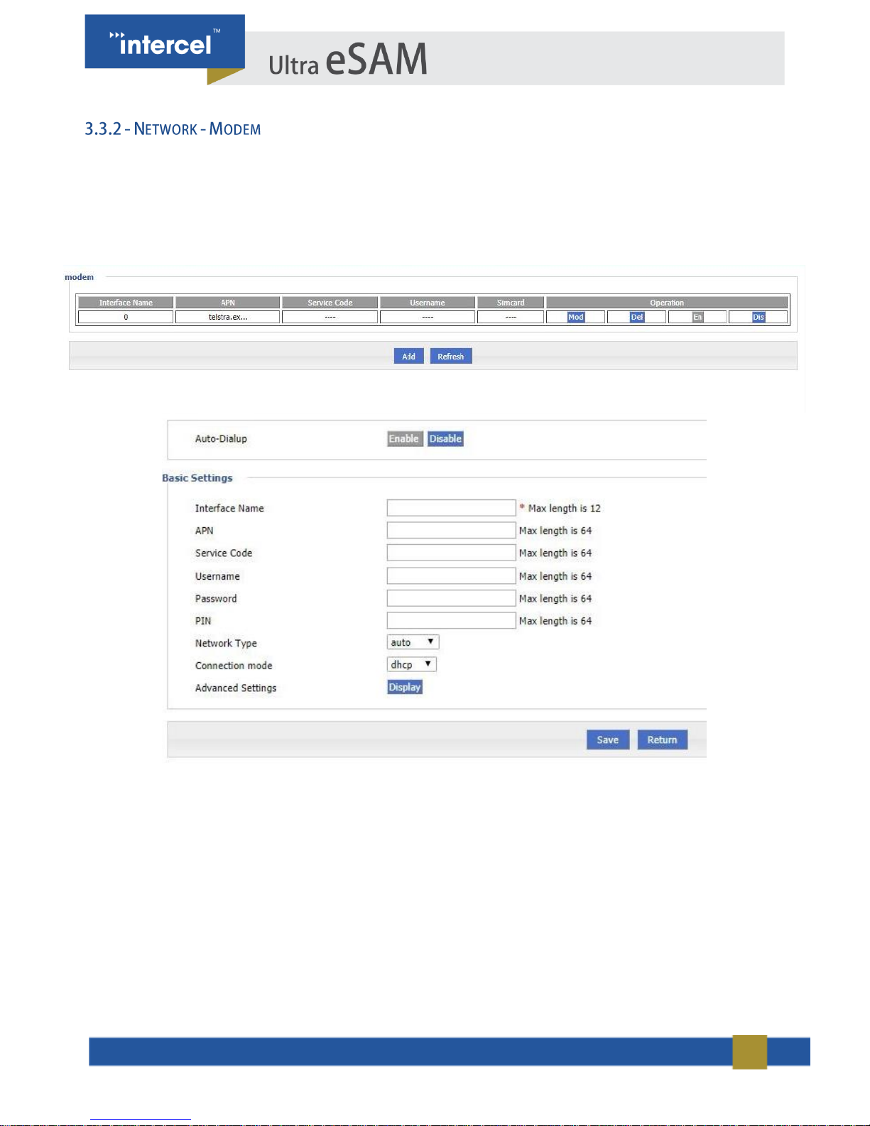
Ultra eSAM functions as a modem allowing other devices to connect to the internet via the Mobile Network. The
Modem screen displays the configuration used by the Ultra eSAM to connect to the 3G/4G network.
1. Single click “Network > Modem”.
2. Single click “add”, and it will display the following page.
FIGURE 10 3.3.2 NETWORK - MODEM 2
FIGURE 9 3.3.2 NETWORK – MODEM
23
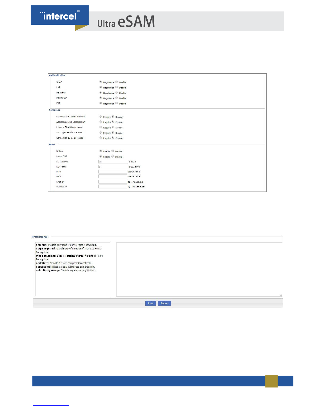
3. Single click “Display” button for Advanced Settings, and the following page will open
4. Input required settings.
5. Single click “Save”, to save settings”.
FIGURE 12 3.3.2 NETWORK - MODEM 4
FIGURE 11 3.3.4 NETWORK - MODEM 3
24
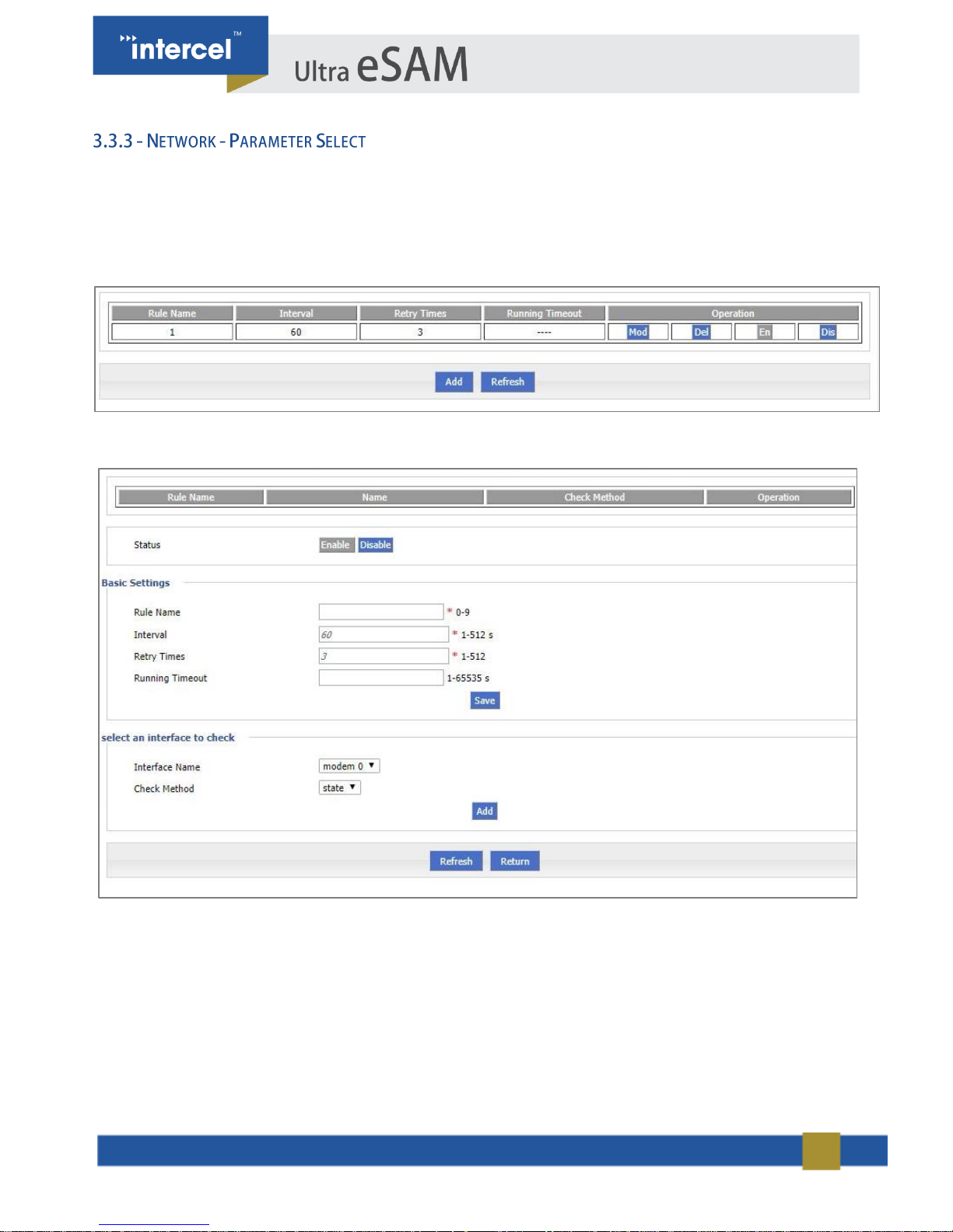
Ultra eSAM’s ‘Parameter Select’ function is used as a multi-function switch and could function as a VPN parameter
switch, SIM parameter switch, or multi-server switch.
1. Single click “Network > Parameter Select”.
2. Add, modify, delete, enable and disable the parameter select rule.
3. Single Click “Add” to get to the following page.
FIGURE 13 3.3.3 NETWORK - PARAMETER SELECT 1
FIGURE 14 3.3.3 NETWORK - PARAMETER SELECT 2
25
4. Input required settings from the table below:
PARAMETER
DETAILS
OPERATION
Status
If ‘Enabled’ only one rule runs
at a time. If it fails when
checked, the next rule starts
running
For status ‘Disabled’ rule: All
related interfaces also become
disabled.
Enable
Disable
Basic Settings
Rule name
Name value decides running
order
Value area : [0,9]
Interval/Retry Times
Check interval and retry time, if
all checks fail, it will switch to
the next rule
Value area :1~512
Units: seconds/time
Default: 60/3
Running timeout
Not available for rule 0
This parameter restricts
current rule, when timeout
occurs, it switches to rule 0. If
rule 0 is not set, it switches to
the next rule.
Value area :1~65535
Units: seconds
Select an interface to check
Interface name
Sets related modem interface
Dropdown List
Check method
If ‘State’ is selected, router will
check link state
If ‘ICMP’ is selected, router will
ping the ICMP IP address to
check if the internet is avalible
Dropdown List
state
ICMP
TABLE 5 3.3.3 PARAMETER SELECT
5. Click on ‘Save’ to save the settings.
26
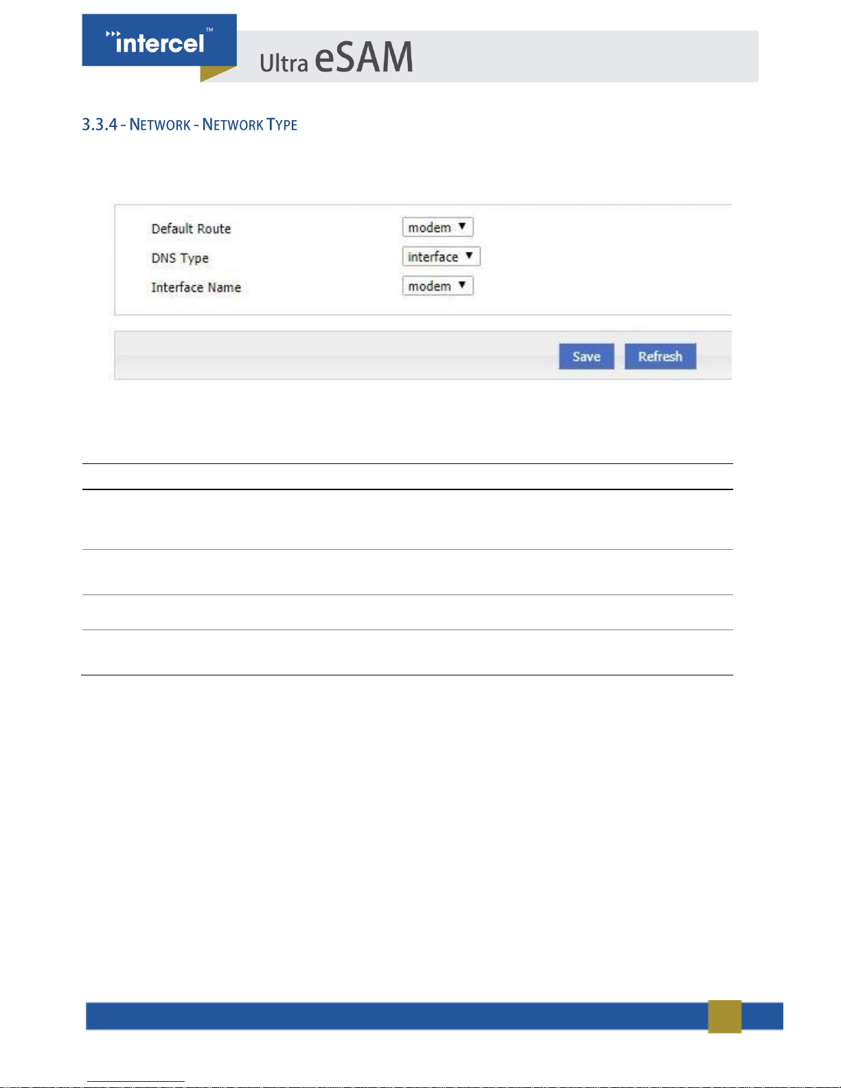
1. Single click “Network > Connection type”.
FIGURE 15 3.3.4 NETWORK - NETWORK TYPE
2. Input required settings.
PARAMETER
DETAILS
OPERATION
Default route
Default route
Dropdown List:
modem
eth0
eth1
DNS type
If Interface is selected, it will
determine DNS automatically
Dropdown List
interface
custom
DNS1/DNS2
Manually sets DNS
Example: 8.8.8.8
Interface name
Router will get DNS address
from this interface
Dropdown List
modem
eth0
TABLE 6 3.3.4 NETWORK - NETWORK TYPE
3. Single click “Save”, to save settings.
27
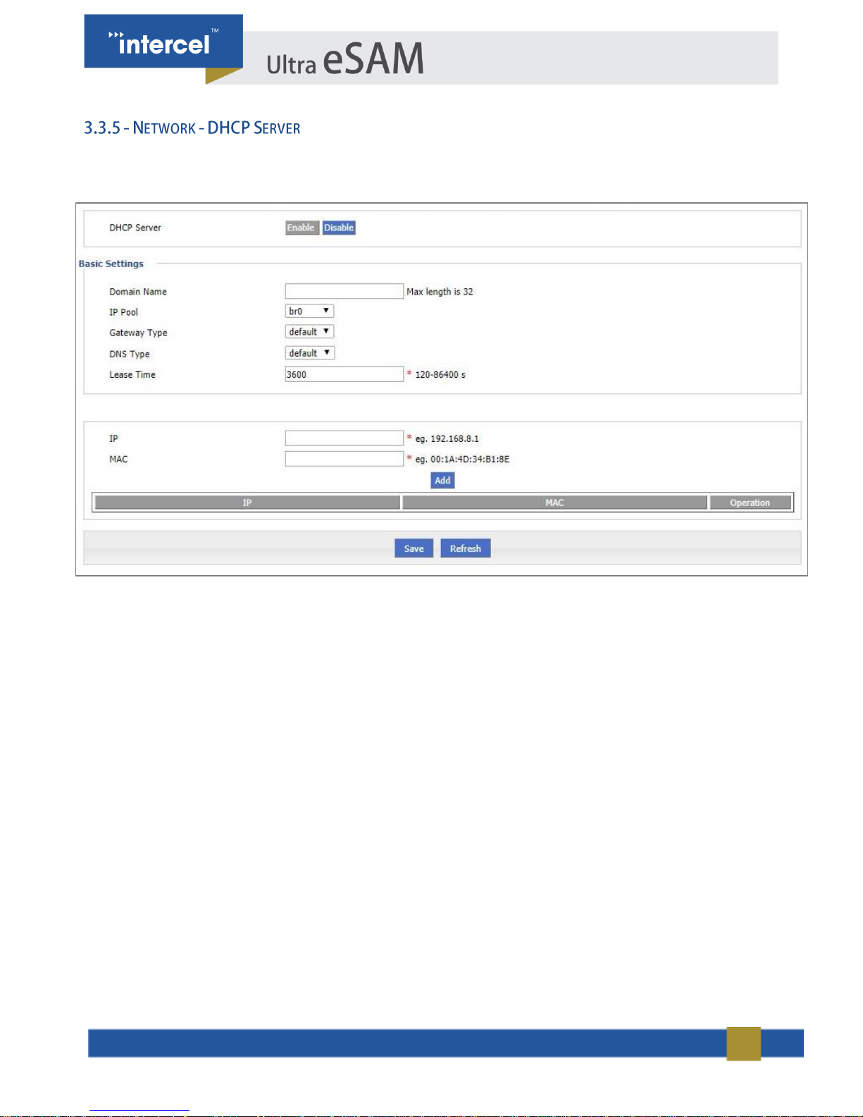
DHCP (Dynamic Host Configuration Protocol) is a LAN protocol which enables the router to assign IP Addresses to its
Clients automatically. This removes the requirement to assign IP Addresses to each device manually.
FIGURE 16 3.3.5 NETWORK - DHCP SERVER

28
PARAMETER
DETAILS
OPERATION
DHCP Server
Enable or Disable the DHCP server
Enable
Disable
Basic settings
IP Pool
The DHCP client can automatically choose its
IP Pool range from a given interface, or it can
be assigned manually using the ‘custom’
option.
Dropdown List
br0
custom
Start IP
When IP Pool is set to ‘custom’, this is the
start of the IP Range the DHCP Server will
offer to clients.
Manual input
Format:A.B.C.D/Mask
Example:192.168.8.2
End IP
When IP Pool is set to ‘custom’, this is the
end of the IP Range the DHCP Server will
offer to clients.
Manual input
Format:A.B.C.D/Mask
Example:192.168.8.254
Gateway
Type
DHCP client access gateway IP source – the
gateway the DHCP server will assign to
clients
Dropdown List
Default value:default
DNS Type
The source of the DNS IP Address that the
DHCP Client will provide to clients. We
generally do not recommend modifying this
configuration.
Dropdown List
default
modemeth0
br0
custom
Lease Time
When the DHCP Server provides an address
to a client, it only leases it for a set amount of
time. Once this expires, the IP will be freed
and the client must apply for a new address.
Value area:120-86400
Units:seconds
Default value:3600
IP & MAC Bindings
IP
Used to set a specific IP to a specific client.
This specifies the IP to be set to that specific
client.
Manual input
Format:A.B.C.D/Mask
Example:192.168.8.2
MAC
This specifies the MAC Address of the Client
that will receive the IP Address entered above.
WORD Type MAC Format
Example: 00:1A:4D:34:B1:8E
TABLE 7 3.3.6 NETWORK - DHCP SERVER

29
ICMP allows the router to determine if the connection it has through the modem is still active. If reception is lost after
initialising the connection, the modem may not know it is no longer connected. ICMP routinely pings a given IP
address to check if the network is down and if it is unable to maintain a connection it will execute a provided operation
to restore network connectivity.
1. Single click “Applications > ICMP Check” and “ICMP Check” tab will automatically appear.
FIGURE 7 3.4.1 APPLICATIONS - ICMP CHECK 1
2. “Add”, “Modify”, “Enable”, and “Disable” the functions of “ICMP check”. Single Click “Add”.
FIGURE 8 3.4.1 APPLICATIONS - ICMP CHECK 2

30
Once connected to the internet, the Modem will be assigned an IP Address by the Internet Service Provider (ISP).
This IP Address can then be used to connect to the modem remotely over the internet – however, the assigned
Address is not fixed and may change in the future. To maintain connectivity, the router is able to connect to a Dynamic
DNS Service in order to provide a fixed IP address through the DDNS Service.
FIGURE 9 3.4.2 APPLICATIONS - DDNS CONFIGURATION 1

31
PARAMETER
DETAILS
OPERATION
DDNS Service
Set DDNS service function to
Enable/Disable
Button
Enable
Disable
Basic Configuration
Service Provider
Select the DDNS service provider that
you wish to use.
Dropdown List options
3322
88ip
Dnsexit
Dyndns
Zoneedit
changeup
custom
Server IP or Domain
When "custom" in "service provider" is
selected, "Server IP or Domain" will
need to be configured with the IP or
domain of the DDNS Server.
For customised protocol, please
contact our technical support.
When "custom" in "service
provider" is selected,
"Server IP or Domain" will
be configured. The default
is standard DDNS protocol.
For customized protocol,
please contact our technical
support.
Basic Configuration
Server Port
Set the port number of the DDNS
server provided by the service
provider. The default port number is
80
Value area: 1~65535
If empty, the default port is
80
Username/Password
Set username/password of the DDNS
service registered in the service
provider
Normal WORD type/CODE
type, max 64 bytes
User Domain
Set the domain of the DDNS service
provided by the service provider
Normal WORD type, max
64 bytes
Update Interval
Set the interval of the DDNS client
obtains new IP, suggest 240s or
above
Value area: 120~86400
Unit: seconds
TABLE 8 3.4.2 APPLICATIONS - DDNS CONFIGURATION

32
DTU (Data Transfer Unit) is used to transfer RS232 serial data across the internet. ULTRA ESAM supports TCP/UDP
Client/Server mode.
Click “Applications > DTU” to open “DTU” tab.
FIGURE 19 3.4.3 APPLICATIONS - DTU CONFIGURATION

33
PARAMETER
DETAILS
OPERATION
DTU Service
Enable or Disable DTU Service
DTU Service options
Enable
Disable
Basic Configuration
Work Mode
Server: 3G/4G router act as TCP/UDP server
Client: 3G/4G router act as TCP/UDP client
DDPClient: 3G/4G router act as UDP client with
Intercel protocol
Select from Dropdown List
Server
Client
DDPClient
Local Port
DTU service port
Specify the port number:165535
Basic Configuration
Protocol
Protocol of TCP/UDP connection
TCP protocol is a connection-oriented reliable
transport protocol for high-reliability requirements
and for communication efficiency, which is not high
degree of sensitivity of the occasion
UDP protocol is a connectionless unreliable
transport protocol, suitable for relatively highefficiency requirements, and the occasion of
relatively low reliability
Select protocol: TCP or UDP
Note:
When the work mode is "DDP
clients," only support "UDP
protocols used in conjunction
with the DDP protocol.”
Received Timeout
Timeout for the DTU Service. When this time is
exceeded, it will assume that the data sent over
TCP/IP or UDP is complete.
Specify time according to your
need
data:1-65535ms
Default value:500
Units: ms
RS232 Data Timeout
Timeout for RS232. When this is exceeded, it will
assume that data sent via RS232 is complete.
Specify time according to your
need
data:1-65535ms
Default value:500
Units: ms
Server Configuration
Server IP or
Domain
Server IP or domain
Format:A.B.C.D/Mask or
Word Type
Server Port
Server port number
Port number:1-65535
Connect Interval
The reconnect interval is DTU client fails to
connect to DSC server
Manually input:1-65535
Units: second
Retry Times
The retry times is DTU client fail to connect to
DSC server
Manually input:1-65535
Heartbeat Settings
Heartbeat Data
Customize heartbeat data content
Manually input, max length
is 64

34
Heartbeat
Interval
Set heartbeat interval (when there is no data
transfer, the router sends the heartbeat data
content every heartbeat interval)
Manually input:1-65535
Units: second
RS232 settings
Rate
Set the serial port transfer rate
Select from the dropdown
list, according to the
practical settings of DTU
serial port Default: 115200
Parity
Set the data parity
Select from the dropdown
list,
according to the practical
settings of DTU serial port
Value: None, Odd, Even
Default: None
Data bit
Set the data transfer bit
Select from the dropdown
list,
according to the practical
settings of DTU serial port
Value: 5,6,7,8
Default: 8
Stop bit
Set the data stop bit
Select from the dropdown
list,
according to the practical
settings of DTU serial port
Value: 1,2
Default: 1
TABLE 9 3.4.3 APPLICATIONS - DTU CONFIGURATION

35
The Ultra eSAM router system supports the built-in Modbus communication protocol, using the RS232, RS485 or
Ethernet port to transmit Modbus data packets and the serial port or to the network port to communicate.
6. Wiring: Connect the TX, RX, GND of the device to RX, TX, GND of the lower computer
respectively.
7. Click Application Settings> DTU / MODBUS Configuration.
Select "Modbus" for the connection type, open the "MODBUS Configuration" tab, and select a different operating
mode, as shown in Figure 4-16, Figure 4-17, Figure 4-18 and Figure 4-19.
When "modbus_rtu_master" and "modbus_ascii_master" are selected as the "working mode",
the "serverA ip" tab and the "serverA port" tab will be displayed.
When "modbus_rtu_slave" and "modbus_ascii_slave" are selected as the "working mode", the
"Local Port" tab will be displayed. As shown in the figures below.
FIGURE 20 3.4.4 APPLICATIONS - MODBUS CONFIGURATION

36
PARAMETER
DETAILS
OPERATION
Basic Configuration
Work Mode
MODBUS working mode, can be set as:
modbus_rtu_master: The serial port of the router is RTU
Master.
modbus_rtu_master: The serial port of the router is RTU
Slave.
modbus_ascii_master: The lower serial port of router is
ASCII Master.
modbus_ascii_slave: The lower computer of router serial
port is ASCII Slave.
Drop-down list.
Connect Timeout
Modbus TCP connection timeout interval, TCP connection
failure timeout interval will reconnect TCP.
Input manually.
Unit: second
Modbus Timeout
The data sent by the Modbus Master expires. The master
sends the data and does not receive the data returned by
the Slave. Then the next action (determined by the
Master) is executed.
Input manually.
Unit: millisecond
Server A IP
Slave IP.
Input manually.
Unique in Master mode.
Server A port
Slave port.
Input manually.
Unique in Master mode.
Local port
Slave port.
Input manually.
Unique in Slave mode.
Serial port parameter setting
Rate
Serial data transfer rate.
Drop-down list.
Set according to the
actual serial port of DTU.
Default: 300
Parity
Data verification method.
Drop-down list.
Set according to the
actual serial port of DTU.
Value range: None, Odd,
Even
Default: None (no parity)
Databit
Data transmission bit.
Drop-down list.
Set according to the
actual serial port of DTU.
Value range: 5,6,7,8
Default: 5
Stopbit
Data stop bit.
Drop-down list.
Set according to the
actual serial port of DTU.
Value range: 1,2
Default: 1
TABLE 18 3.4.4 APPLICATIONS -MODBUS CONFIGURATION

37
DIDO (Digital Input Digital Output), is used to monitor equipment GPI/O high level input. If it meets a given trigger
condition, the Ultra eSAM can trigger a GPI/O level output and/or SMS output.
The DIDO Service can be found under Application > DIDO
FIGURE 21 3.4.5 APPLICATIONS - MODBUS CONFIGURATION

38
PARAMET
ER
DETAILS
OPERATIONS
Trigger Settings
GPI
Trigger mode, GPI input level.
HIGH: Trigger condition is high
LOW: Trigger condition is low
SQUARE-WAVE COUNT Trigger condition is square
wave
Drop-down list.
Low level is below 5V
High level is 5V ~ 36V
Default: HIGH
Filtering
The duration of the GPI input to reach the trigger
condition.
Input manually.
Unit: hundred milliseconds
Counter Trigger
The number of transitions required to trigger the DIDO
Service.
Input manually.
Counter Period
The amount of time required for an input signal to trigger
the DIDO Service.
Input manually.
Unit: hundred milliseconds
Counter Active
Determine the shape of the square wave
LO-TO-HI:The square wave is from low to high.
HI-TO-LO:The square wave is from high to low.
Drop-down list.
Default value: LO-TO-HI
Counter Start
The time since the DIDO process began to detect square
wave input
Input manually.
Unit: hundred milliseconds
Alarm settings
GPO Enable
Enable or disable GPO alarm mode
Enable
Disable
Button.
Default: Enable
Alarm Action
GPO alarm mode, GPI port output level.
HIGH: GPO alarm is high
LOW: GPO alarm mode is low
SQUARE-WAVE COUNT: GPO alarm mode is square
wave
Drop-down list.
Default: HIGH
Power-On Status
The GPO defaults after the device is powered on
HIGH: GPO defaults high
LOW: GPO defaults to low
Drop-down list.
Default: LOW
Delay
After the condition is triggered to output square wave time
Input manually.
Unit: hundred milliseconds
Low
Square wave output low sustained after the time
Input manually.
Unit: hundred milliseconds
High
Square wave output sustained high time
Input manually.
Unit: hundred milliseconds
Output
The number of square waves output by the GPO at the
trigger condition
Input manually.
Recover Time
Wait for the recovery time to trigger again after the device
alarms
Input manually.
Unit: second
Keep on
GPO output level duration
Input manually.
Unit: hundred milliseconds

39
SMS Enable
Enable / Disable SMS alarm mode
single button.
Default: Disable
SMS Num
The phone number to send SMS alerts
Input manually.
SMS Msg
SMS message alert to send the contents of the message
Input manually.
TABLE 19 3.4.5 APPLICATIONS -MODBUS CONFIGURATION
1. Click “Save” to complete the DIDO configuration.
. The DIDO function needs to be used with the GPIO port of the serial port

40
GPS is to transfer GPS data the device gets from the GPS satellite system. It uses UDP protocol.
Click “Applications > GPS” to open the “GPS” window
FIGURE 22 3.4.6 APPLICATIONS - GPS CONFIGURATION
PARAMETER
DETAILS
OPERATION
GPS Service
Enable or Disable GPS Service
GPS Service options
Enable
Disable
Basic Configuration
Work Mode
Set the work mode of the GPS
Select from the dropdown list,
Default: Client
Product Mark
The identification of the router
GPS, used for identifying the
device
Word Type, max length is 64
Local Port
The router port for reporting the
GPS data
Value: 1-65535
Server IP or
Domain
Server IP or domain for getting
the GPS data
Format:A.B.C.D/Mask or Word Type
Server Port
Server port for getting the GPS
data
Value:1-65535
TABLE 10 APPLICATIONS - GPS CONFIGURATION

41
SNMP (Simple Network Management Protocol) can monitor routers remotely and monitor the status of routers
(Support interface status check, like VPN, modem etc.).
Click “Applications >SNMP” to open the “SNMP” tab.
FIGURE 23 3.4.6 APPLICATIONS - SNMP CONFIGURATION

42
Ultra eSAM has embedded a WMMP (Wireless Machine-to-Machine Protocol) to connect with an M2M (Machine-toMachine) platform which can remotely monitor and manage the routers and its network. Its configuration is as
follows:
Click “Applications > M2M” to open M2M configuration tab.
To configure the Modem to work with the eSAM cloud service, enter the parameters shown below:
FIGURE 24 3.4.7 APPLICATIONS - M2M CONFIGURATION

43
This application is to control the online time of the router to better manage the network and save 3G/4G data. Ultra
eSAM can add several online periods as per the user’s requirement (e.g. hours per day). Additionally, this application
can support triggering tasks at a given time point (e.g. redial or reboot at 00:00).
1. Click “Applications > Timing” to open “Timing” tab.
FIGURE 25 3.4.9 APPLICATIONS - TIMING CONFIGURATION 1
2. To add a timing task, please click “Add”.
FIGURE 26 3.4.9 APPLICATIONS - TIMING CONFIGURATION 2
3. Configure timing task parameter.
4. Single click “save” icon to finish “Timing” configuration. The “range” selection requires system
clock enable (that is to say the NTP server), while the “interval” selection does not.

44
Ultra eSAM supports VPN (Virtual Private Network) including L2TP/PPTP/GRE/IPIP/IPSEC. Moreover, it
supports VPN OVER VPN, e.g. GRE over IPSec, IPSec over PPTP/L2TP/GRE/IPIP.
VPDN stands for Virtual Private Dial-up Networks. Currently VPDN supports L2TP and PPTP
1. Single Click “VPN > VPDN” to open “VPDN” tab.
FIGURE 10 3.5.1 VPN - VPDN CONFIGURATION 1
2. Click “Add” to add a new VPDN rule.
FIGURE 28 3.5.1 VPN - VPDN CONFIGURATION

45
After a VPDN rule is added, the router will establish VPN communication with service address automatically. To see
the tunnel status, click "View" in "Tunnel" tab.
PARAMETER
DETAILS
OPERATION
VPDN service
To enable or disable the
VPDN rule
Click “Enable”
Basic Settings
Interface name
Name of this VPDN rule
Cannot be modified after save.
Protocol
VPDN protocol, either:
L2TP
PPTP
Select from Dropdown List, cannot be
modified after save.
Service IP or Domain
IP or domain of server
To input the IP or domain of server to
be visited.
Username
Username of server
To input the username.
Password
Password of server
To input password.
Advanced settings
Advanced parameter of
PPP link
Click “Display”
TABLE 11 3.5.1 VPN - VPDN CONFIGURATION

46
Tunnel technology transfers data between networks over the internet. Packets are passed through the tunnel in order
to link two physically isolated networks into one logically linked network. Ultra eSAM supports GRE and IPIP Tunnel
Modes.
GRE (Generic Routing Encapsulation, Generic Routing Protocol Encapsulation) allows for network packets to be
contained within IP packets, suitable for transmission over the internet. This allows for two network devices to be
joined over the internet as if they were joined physically by a network cable. The main functions of the GRE protocol
are internal protocol encapsulation and private address encapsulation.
An IPIP tunnel is a simple solution for IP packet encapsulation between two routers. The IPIP tunnel interface will
function like a physical interface in the interface list and is supported on many routers.
1. Click “VPN > Tunnel” to open “Tunnel” tab.
FIGURE 29 3.5.2 VPN - TUNNEL CONFIGURATION
2. Click “Add” to add a new tunnel.
3. Configure Tunnel rule parameter
PARAMETER
DETAILS
OPERATION
IP Tunnel Service
To enable or disable IP tunnel service
Click “Enable”
Basic Settings
Tunnel name
Name of the tunnel, cannot be modified after
configured
Input the name of
tunnel
Tunnel Mode
Tunnel mode:
gre
ipip
Select from
Dropdown List
Local virtual IP
Virtual IP address of local tunnel
Format: interface
type A.B.C.D/M.
Peer virtual IP
Virtual IP address of peer tunnel
Format: interface
type A.B.C.D/M.
Interface type
To choose “interface” or “static IP”
Select from
Dropdown List.
Local External
interface
This parameter will need to be set if “interface” is
selected in “interface type”. Choose any
connected interface as an external interface.
Select from
Dropdown List.
Local external IP
This parameter needs to be set if "static IP" is
selected for "interface type". It is to set IP
address to external network
Format: interface
type A.B.C.D/M.
Peer external IP
External interface IP of counterpart network
tunnel. Usually, a public IP address also can be
a LAN IP
Format: interface
type A.B.C.D/M.
TABLE 12 3.5.2 VPN - TUNNEL CONFIGURATION

47
1. Click “VPN > IPSec” to open “IPSec” tab.
FIGURE 30 3.5.3 VPN - IPSEC CONFIGURATION 1
2. Click “Add” to add a new IPSec rule. There are 3 phases of IPSec configuration:
FIGURE 31 3.5.3 VPN - IPSEC CONFIGURATION 2

48
3. Configure phase 1 configuration.
PARAMETER
DETAILS
OPERATION
Basic Settings
Select
To select which phase of
IPSec, phase 1, phase 1 or
phase IPSec
Select “Phase 1”
Policy Name
Name of phase 1, mainly to
match phase “IPSec”
To input the name of phase 1.
Cannot be changed after save.
Initial Mode
To choose “main” or “aggr”
Select from Dropdown List,
“aggr” is recommended
Encrypt
Supports 3des and aes
Select from Dropdown List
Hash
Supports md5 and sha1
Select from Dropdown List
Authentication
To select authentication
Select from Dropdown List,
presently only “PSK”
supported
Pre Share Key
To set pre-share key
Max 24 letters
Self Identify
To set the self ID of IPSec
To input, the ID, need to match
the ID of another side
Match Identify
To input the match ID of
IPSec
To input match ID, need to
match ID of another side
IKE Lifetime
Lifetime of IKE key
Value area: 120~86400
Unit: second
Group Name
Select group
Select from Dropdown List
DPD Service
To enable DPD service
To click “Enable”
DPD Delay
To set DPD check interval
time
Manual input
Value area: 1~512
Unit: second
DPD Retry Times
Max times to continuous DPD
check failure.
Manual input
Value area: 1~512
TABLE 13 3.5.3 VPN - IPSEC CONFIGURATION
4. Click “save” to finish phase 1 configuration.
5. Click “Add” to add a new IPSec rule
In above parameters, “Initial Mode”, “Encrypt”, “Hash”, “Authentication” “Pre-Share Key”, “IKE Lifetime”,
“Group Name” need to match parameter of IPSec server. “Self-Identify” and “Match Identify” needs to
match “match Identify” and “Self-Identify” of IPSec sever respectively.

49
FIGURE 32 3.5.3 VPN - IPSEC CONFIGURATION 3
6. Configure phase 2 configuration.
PARAMETER
DETAILS
OPERATION
Basic Settings
Select
To select which phase of IPSec,
phase 1, phase 1 or phase IPSec
Select “Phase 2”
Policy Name
Name of phase 2, mainly to match
phase “IPSec”
To input the name of phase 2. Cannot
be changed after save
Encryption
Protocol
Supports esp, ah, ah+esp
Select from Dropdown List
Encrypt
Supports des, 3des, aes
Select from Dropdown List
Hash
Supports md5 and sha1
Select from Dropdown List
Group Name
Need to be configured, when PFS
is “open”, to set the key length of
SA initial of phase 2
Select from Dropdown List
PFS
To open or close PFS
Select from Dropdown List
Lifetime
IPSec SA key lifetime
Value area: 120~86400
Unit: second
Transport Mode
Supports tunnel, transport, and
auto.
Select from Dropdown List
Local Subnet
Set local subnet
No need to set for “transport” mode, only
for “auto” and “tunnel”. Format:
A.B.C.D/M
Remote Subnet
To set local subnet
No need to set for “transport” mode, only
for “auto” and “tunnel”. Format:
A.B.C.D/M
TABLE 14 3.5.3 VPN - IPSEC CONFIGURATION 2
7. Click “save” to finish phase 2 configuration.

50
8. Click “Add” to add a new IPSec rule.
FIGURE 33 3.5.3 VPN - IPSEC CONFIGURATION 4
9. Configure IPSec configuration
PARAMETER
DETAILS
OPERATION
Basic Settings
Select
To select which phase of IPSec, phase
1, phase 1 or phase IPSec
Select “IPSec”
Interface Name
Name of this phase
Input name
Match Phase1
To select a matching name of “phase1”
Select from Dropdown List.
Match Phase2
To select a matching name of “phase2”
Select from Dropdown List
Destination IP or Domain
counterpart IPSec server IP or domain
Input counterpart IPSec server
IP or domain
Encryption Interface
To select binding interface of IPSec. To
bind VPDN/modem/br0 as a local
interface of IPSec initial can support
IPSec OVER VPDN. In addition, after
binding, IPSec rule will change as per
the charge of bonded interface. Thus,
can resume link of IPSec dialling
interface and keep IPSec linked as
soon as possible
Select from Dropdown List
TABLE 15 3.5.3 VPN - IPSEC CONFIGURATION 3
10. Click “Save” to finish IPSec configuration.

51
Open VPN implements a VPN built atop the Open SSL Library. Compared with a traditional VPN, it is simpler and
easier to use.
The UDP Protocol is enabled by default and is recommended, but TCP is also available.
Open VPN connections can transverse thorough most proxy servers and through Network Address Translation. Its
server side configures some network configuration information (including IP address, route configuration and so on)
on the client. Open VPN offers two types of interfaces for networking via the Universal TUN/TAP driver. It can create
either a layer-3 based IP tunnel (TUN), or a layer-2 based Ethernet TAP that can carry any type of Ethernet traffic.
Port 1194 is the official IANA (Internet Assigned Numbers Authority) assigned port number for Open VPN.
Single Click "VPN > Open VPN" to open the OpenVPN Window.
FIGURE 34 3.5.4 VPN - OPEN VPN CONFIGURATION
1. Upload the required Certificate files using the ‘files’ menu.
2. Configure Open VPN parameters.
3. Click “Save” to finish Open VPN configuration.

52
The forward function of Ultra eSAM 3G/4G router includes NAT, Routing, dynamic routing (RIP, OSPF) (optional) and
QOS (optional).
DNAT is used to replace the destination address of packets accessing the external network; the router will replace the
destination address of packet accessing the external network with the user’s custom settings. Click “Forward > NAT”
to open “NAT” tab.
FIGURE 35 3.6.1 FORWARD CONFIGURATION 1
FIGURE 36 3.6.1 FORWARD CONFIGURATION 2

53
SNAT is the source address translation and its role is to translate source address of IP packets into another address.
FIGURE 37 3.6.1 SNAT CONFIGURATION RULE
PARAMETER
DETAILS
OPERATION
Protocol
Defines the protocol of the
packets the NAT should
modify
Dropdown List
all
TCP
udp
ICMP
Original Address
The source address is needed
to be replaced
Manual input
Format1:A.B.C.D
Format2: A.B.C.D/Mask
Original Port
The port of external IP, the
port needs to be replaced
Value area: 1-65535 or [1-65535], it
can be a range or a single port
Mapping Address Type
Internal IP address
Dropdown List
interface
static
Interface
Select the interface of the
router as source address after
replacement
Dropdown List
br0
modem
eth0
eth1
Mapping Port
The new port which replaces
the original port of source
address.
Value area: 1-65535 or [1-65535], it
can be a range or a single port
TABLE 16 3.6.1.2 SNAT CONFIGURATION RULE

54
MASQ is MASQUERADE.
FIGURE 38 3.6.1 MSAQ 1
FIGURE 39 3.6.1 MSAQ 2
MASQ rule: the source address of all packets in the LAN need to be transferred into the specific IP address of the
router, so the PC from the LAN can send packets out. If MASQ rule in the router will be deleted, the router LAN of the
PC cannot communicate with the external network.

55
Static routing can forward packets according to a manually configured routing path. This page is divided into static
routing and policy routing. Policy Routing allows for a priority to be set on different configurations, allowing multiple
configurations to co-exist.
The forwarding router detects the received packet's source address and then forwards packages according to the
matching policy. The routing priority setting can be used to set the priority from 3 to 252, where smaller numbers
indicate higher priority. Policy based routing always has a higher priority than static routing.
FIGURE 39 3.6.2 FORWARD - ROUTING

56
PARAMETER
DETAILS
OPERATION
Basic Settings
Routing Type
To select “Static Route” or “Policy Route”
Dropdown List
When Routing Type is “Static Route”
Network
Set the destination IP address and
subnet mask of static route
Manual input
Format1: A.B.C.D/Mask
Gateway
Type
Specify gateway type of static routing,
includes:
interface
static IP
Dropdown List
Gateway
Set a next hop IP address of static
route, IP address of the adjacent
router interface
Dropdown List
If the gateway type selects static IP,
gateway needs to be manually input,
format: A.B.C.D
If the gateway type is ‘select interface’,
the gateway is needed to be selected
from dropdown list
When Routing Type is “Policy Route”
Source
Type
Set source type of policy route
Static IP
Interface
Dropdown List
Network
It can be configured when “static IP” is
selected in source type, by adding IP
address or subnet manually.
Manual input
Format1: A.B.C.D/Mask
Source
Interface
When source type is policy route,
need to manually set source network
address of policy router
Modem
Dropdown List
Gateway
Type
Set the next hop IP of policy route
static IP
interface
Dropdown List
Gateway
When the gateway type is set to
"Static IP", fill in with the IP address,
when gateway type is “interface", it will
use the selected interfaces as
gateway
Manual input
Format1: A.B.C.D/Mask
Priority
Set up the routing priority, lower
number will have the higher priority.
Value area:[3,252]
TABLE 17 3.6.2 FORWARD - ROUTING
Static routing will forward according to the destination address of the packet if the router received the
packet (e.g. source address is 1.1.1.1 destination address is 2.2.2.2), It will forward the packet to next
hop according to the route which meets with the destination address (2.2.2.2).
It will forward the packet to next hop according to the route which meets the destination address
(2.2.2.2).
Policy routing will forward according to the source address of the packet if the router received the packet
(e.g. source address is 1.1.1.1 destination address is 2.2.2.2), it will forward the packet to next hop
according to the route which meets with the source address (1.1.1.1).
Policy routing has higher priority than static routing, policy-based routing priority regardless of how much.

57
QoS (Quality of Service) is a security mechanism for the network enabling the configuration of priorities and bandwidth
allocations for devices or subnets. When the network is overloaded or congested, QoS ensures that critical traffic is
not delayed or dropped.
1. Click “Forward > QoS” to open “QoS” tab.
2. Click Add to create a new QoS rule.
3. QOS configuration parameter, configuration parameter instruction
4. Single click “Save” icon to QOS setting.
QoS is mainly used to allocate the average bandwidth for the users which access the Internet through the router or to
assign specific users with more bandwidth. If the router is connected to two subnets: 192.168.8.1/24 and
192.168.9.1/24, the router QOS can control the rate of these two subnets; If the router's bandwidth is relatively high,
the router can adjust the bandwidth based on priority and redundancy of two subnets, that is, the router meets the
high priority redundancy bandwidth first, then meets the low priority subnet redundancy bandwidth.
FIGURE 40 3.6.2 FORWARD - ROUTING
FIGURE 41 3.6.2 FORWARD - ROUTING

58
RIP protocol (Routing Information Protocol) is the most widely used IGP (Interior Gateway Protocol). It was designed
to be used in small networks and is only recommended for this use case. For more complex environments, generally,
do not use the RIP protocol.
1. Click “Forward > RIP” to open “RIP” tab.
2. Click “Add” to add a new RIP route, configuration interface.
3. Configure RIP route parameter instruction.
4. Single click “save” icon to RIP route setting.
5. Click “Forward > OSPF” to open “OSPF” tab.
6. Click “Add” to add a new OSPF route.
7. Configure RIP route parameter instruction.
8. Single click “save” icon to OSPF route setting.
9. Single click “save” icon to finish
PARAMETER
DETAILS
OPERATION
OSPF Service
Enable or disable OSPF Service
Click the button to select
Enable
Disable
Redistribute Connected
Enable or disable Redistribute Connected
Click the button to select
Enable
Disable
Redistribute Static
Enable or disable Redistribute Static
Click the button to select
Enable
Disable
Redistribute Kernel
Enable or disable Redistribute Kernel
Click the button to select
Enable
Disable
TABLE 18 3.8 DYNAMIC ROUTING

59
PARAMETER
DETAILS
OPERATION
Add Type
Add the type of OSPF route
Click the button to select Add Type
Network
Neighbour
Interface
When Add Type is “Network”,
Network
Set the network address of
ospf sending address
Manual input
Format1: A.B.C.D/Mask
AS Number
Used to identify the network
(only the routers with the
same domain address can
exchange routing information)
Manual input
Value area: [0,65535]
When Add Type is “Neighbour”,
Neighbour
The router can reach in the
next hop
Manual input
Format1: A.B.C.D/Mask
When Add Type is “Interface”,
Interface Name
The interface of the router
Dropdown List
br0
modem
eth0
eth1
Interface Attribute
Configure the router interface
attribute, include cost and
network
Click the button to select
cost
network
Cost
Configure the cost of the
router interface, used to learn
routing table
Manual input
Value area:1-65535
Network Type (when the interface
attribute is network)
Configure the network type of
the router interface
Dropdown List
broadcast
non-broad
point-to-multipoint
point-to-point
TABLE 19 3.9 DYNAMIC ROUTING 2
OSPF is a link-state routing protocol, commonly used for the same routing domain. Here, the routing
domain is an autonomous system, in which the routers can switch routing information through a unified
network switching or routing protocol routing policy. All OSPF routers maintain an identical description of
the network structure, which is used to calculate its OSPF routing table.
As a link-state routing protocol, OSPF link state broadcast data LSA (Link State Advertisement) sent to
all routers in an area, which is different from the distance vector routing protocols. Distance vector routing
protocol passed some or all routing information of the routing table to the adjacent routers.

60
"Security" will filter packets to decide which are allowed to pass through the modem and which should be blocked.
Ultra eSAM supports IP filter, domain filter and MAC filter.
IP Filter allows you to blacklist or whitelist packet’s according the Source or Destination IP Address.
1. Click “Security > IP Filter” to open “IP Filter” tab.
FIGURE 42 3.9.1 SECURITY - IP FILTER 1
2. In the forwarding filtering rules.
a. Black List: Packets which meet the filtering rules are not allowed to be forwarded through the router
and are discarded.
b. White List: Only the packets which do meet the filtering rules are allowed to be forwarded.
3. Click “Add” to add a new IP filter rule and configure IP filter parameter. There are two types of IP filter: “Input”
and “Forward”.

61
FIGURE 43 3.9.1 SECURITY - IP FILTER 2
FIGURE 44 3.9.2 SECURITY - IP FILTER 3

62
Domain filter support’s blacklist and whitelist. It is used to forbid PCs in LAN from visiting some websites or allows
them to visit only specific websites.
Click “Security> Domain Filter” to open “Domain Filter” tab.
FIGURE 45 3.9.2 SECURITY - DOMAIN FILTER 1
FIGURE 46 3.9.2 SECURITY - DOMAIN FILTER 2

63
Click “Security> MAC Filter” to open “MAC Filter” tab. Here, you can add a list of MAC Addresses to allow access into
the network from the internet or to block from accessing the network from within the network.
FIGURE 47 3.9.3 SECURITY - MAC FILTER

64
Remote Access allows you to configure what methods are enabled to access the modem remotely. SSH and TELNET
are methods for accessing the modem’s command line and the WEB interface refers to the browser-based GUI you
are using to configure the modem now.
If enabled, these methods can be used to access the modem from the mobile network.
FIGURE 48 3.9.4 SECURITY - MAC FILTER
The parameters of remote access are described in the following table.
PARAMETER
DETAILS
OPERATION
SSH
The terminal uses ssh2 to access the router
1. Enable:Open the Modem port SSH function, the
terminal can use ssh2 to access the router CLI
2. Disable:Disable the Modem port SSH function, the
terminal can use ssh2 but cannot access the router CLI
Single button
Default: Disable
TELNET
The terminal uses telnet to access the router
1. Enable:Open Telnet function of the Modem port, the
terminal can use Telnet to access the router CLI
2. Disable:Disable the Telnet function of the Modem port,
the terminal can use telnet to access the router CLI
Signal button
Default: Disable
WEB
The terminal uses WEB way to visit the router
1. Enable:Enable the terminal to access the router WEB
page via the modem port
2. Disable:Disable the terminal through the Modem port
to access the router WEB page
Signal button
Default: Disable
TABLE 20 3.9 REMOTE ACCESS

65
“System” gives you access to the modem’s logs and allows you to configure system parameters.
1. Click “System > Local Log” to open “Local Log” tab.
FIGURE 49 3.10.1 LOCAL LOG
2. Select the type of "Local Log" and then click "View" to see the log. Click “Clear” to clear the log info in the “Log
Table”, and click “Export” to export log in your local PC.
There are 3 types of logs:
a. Message: system log, to record the running log of the router, usually for most of the users.
b. Application: application program log, to record the Open or close of some application programs.
c. Kernel: kernel log of a router, usually for R&D engineers.
To see “local log”, “remote log” must be enabled.

66
Click “System > Remote Log” to open “Remote Log” tab.
FIGURE 50 3.10.2 REMOTE LOG

67
Click “System > Clock” to open “Clock” tab.
FIGURE 51 3.10.3 CLOCK
PARAMETER
DETAILS
OPERATION
Status
To enable or disable Time
Synchronization service
To click “Enable” or
“Disable”
Time Synch. Type
Type to synchronize system time
Select “NTP” or
“Manual”
When select “NTP” in “Time Synch. Type”
NTP Server IP or
Domain
IP or domain of NTP server
Select from Dropdown List
NTP Server Backup
Backup NTP server
Manual input server domain
or IP address
NTP Synch. Interval
Interval for NTP client to check time
with NTP Server. E.g. every 10
minutes
Value area: 1~65535
Unit: second
Default: 600 s
Time Zone
Time Zone
Select from Dropdown List
Time Zone Number
For “Custom” option in “Time Zone”.
E.g. +8 or -4
WORD type
When select “Manual” in “Time Synch. Type”
Set Date
To set date
YYYY-MM-DD
e.g. 1970-01-01
Set Time
To set time
HH: MM: mm
E.g. 07:01:01
TABLE 21 3.10.3 CLOCK

68
"Account" is to change username/password, change web port and restrict other users from visiting the router.
Step 1 Click “System > Account” to open “Account” tab.
FIGURE 52 3.10.4 ACCOUNT
Step 2 Set account parameters.
Step 3 Click "Save" to finish configuration. After saving, the user needs to log in again.

69
This screen allows you to ping addresses from the modem and to trace the route the modem takes to access
different IP Addresses. It can be used to test the modem’s connectivity, both inside and outside the network.
1. Click “System > Network Test” to open “Network Test” tab.
FIGURE 53 3.10.5 NETWORK TEST
2. Input IP address or domain to be tested in "Destination", click "Ping, to check whether the
router can be linked to a destination.
PARAMETER
DETAILS
OPERATION
Destination
To input IP address or domain
to be tested
Input IP address or domain
to be tested
Ping
To use Ping to test link
Click “Ping”
Trace
To use Trace command to test
hops from the router to
destination
Click “Trace”
Result
Test Result
TABLE 22 3.10.5 NETWORK TEST

70
Ultra eSAM supports firmware upgrading.
Step 1 Click “System > Files” to open “Files” tab.
FIGURE 54 3.10.6 FIRMWARE SETTING
Step 2 Click “Choose File” to select upgrading file and then click “Upgrade”.

71
If the upgrading file is larger than 6MB, CFE mode upgrading should be used to upgrade.
1. Set IP of your computer to
192.168.1.123
255.255.255.0
2. Don’t set the default gateway or DNS.
3. Power off the router (take the power cable out).
4. Press and hold the RESET button between the two 4G antenna ports. Do not release it.
5. While holding the RESET button plugin the power cable in. Wait for 3 to 4 seconds, then release the
RESET button. You will see the lights flashing (NOTE: if RESET is not released at the right time, device will
not enter the upgrade mode)
Enter 192.168.1.1 in your browser, you will see the following page. If not, please start over again from step 1.
FIGURE 55 3.10.6.2 CFE MODE UPGRADING
Select the firmware, click upload to upgrade and you should see the following page.
FIGURE 56 3.10.6.2 CFE MODE UPGRADING 2
Wait for 3 minutes or (You can add two IP addresses to your network card: 192.168.1.123 and 192.168.8.123. Then
you can ping 192.168.8.1 during this period. When you receive a ping response, it means an upgrade is done.)

72
The Ultra eSAM provides USB port and you can choose USB mode to upgrade the router. This requires using a telnet
client to initiate the upgrade:
1. Enter the password of the telnet to enter in the system, as shown in the figure.
FIGURE 57 3.10.6.3 USB UPGRADE
2. Add a folder ‘udisk_upgrade’ to the FAT32 format USB drive.
3. Copy the upgraded firmware to the ‘udisk_upgrade’ folder
4. Plug the USB drive into the USB interface of the device. The system will be upgraded
automatically.
5. The status LED’s will remain on for 3 ~ 5s.The modem will reboot itself when the upgrade is
complete.

73
Ultra eSAM is capable of backing up and restoring its configuration file.
3. Click “Browse” to select a configuration file to be imported. And then click “Import” to resume
the configuration as the configuration file.
4. Click "Export" to export configuration file and save it to local PC.
FIGURE 58 3.10.6.4 BACKUP SETTING
After import, the router will reboot automatically.
"Key": if a key is an input when exporting configuration file, this key need to be input in import.
Not more than 8 digits of the key can be used as input.

74
This setting can be used to reset Ultra eSAM to its original factory configuration. Using the ‘save’ and ‘load’ functions it
is possible to save the devices configuration and then reload this configuration at a later point. If this saved
configuration is deleted, then the device will be restored to its default settings.
FIGURE 59 3.10.6.5 FACTORY SETTING
Save: to save the current setting as default factory configuration setting.
Load: to resume default factory setting.
Use this menu to delete any unwanted firmware patch files.
FIGURE 60 3.10.6.6 PATCH OPERATION FUNCTION

75
Click “Reboot” to restart the router or click “Refresh” to refresh the page.
FIGURE 61 3.10.6.7 REBOOT/REFRESH

76
The "RESET" button is on the rear panel and next to power interface. This button can be used when the router is in
use or when the router is turned on. There are 3 functions to press "RESET" button when the router is in use:
5. Press "RESET" for about 2 seconds, the router will reboot.
6. Press “RESET” 5-10 seconds, the router will reboot and will be reset to the default factory
configuration.
7. Press “RESET” over 20 seconds, the router will reboot, and get into CFE upgrading. The
router is resumed to default factory setting configuration.
8. Press “RESET” button and turn on the router, and keep pressing “RESET” for 2 seconds. The
router will get into CFE upgrading mode.

77
This section details some typical usage scenarios for the Ultra eSAM Modem.
Scenario
The Ultra eSAM is ensuring the reliability and accuracy of the network links. If an anomaly is detected,
predefined actions are performed. In this scenario the Ultra eSAM functions as an error detection and report
machine.
Parameter Configuration
In this scenario, you need to have the ICMP detection configured; see the section on ICMP detection for more
information.
Application Result
When the modem connects, the ICMP detects the destination address or backup address and determines that
the connection was in fact successful.
When a router succeeds in dialing, but fails to connect to the network, the ICMP test fails and corrective action
is taken, such as a modem-reset.
Scenario
The Ultra eSAM can link serial devices, such as PLC’s or RTU’s, together over the mobile network utilising
TCP and SSCOM Serial Interface Software.
Parameter Configuration
This scenario needs the "DTU" configuration, as detailed in the section 4.3.3 DTU configuration.
One eSAM can be used as a server and another can function as the client. Link the two using the DTU
configuration to bridge their serial ports together across the internet.
Application Result
The eSAM client and eSAM host are able to link RS232 devices over the internet.

78
Typical Case
Ultra eSAM provides s parameter select function. When one configuration of the modem fails (such as
connecting to a server, or connecting to an ISP), it is able to change to a backup configuration.
Parameter Select
When the active L2TP link is disconnected from the server, the router will perform parameter switching
based on the "check ICMP" function, to detect whether the connection is interrupted; if Ping failure occurs
(for 3 times), the router will switch to the PPTP link and maintain connection of the server.
Application Result
When the modem detects a failure in the L2TP VPN Connection, it will automatically switch itself to a
backup VPN server.
Introduction
VPN (Virtual Private Network) is a technology allowing two devices to be connected in a private network over the
internet. These two (or more) devices are able to communicate as if they are on the same LAN, when they are in
fact a great distance apart and connected over the internet.
Multiple VPN services are available; we recommend contacting Intercel for specific advice.
.
Result
After setting Ultra eSAM and company router parameters, they can connect to each other remotely.

79
Typical Application
Ultra eSAM can perform tasks on a timer. The router can be set to turn itself on, off or reboot at a given time
based on the required availability.
Result
The router will be online at 10:05 AM and remain online until 10:08 AM. It becomes offline at 10:09 AM and
router will reboot every 24 hours.

80
Issue
None of the LED’s on the router are flashing or illuminated.
Possible Reason
Power supply is not suitable, it should be 5-36VDC
No power supply
Solution
Make sure the power supply is 5~36VDC
Check the power adapter and cable connection
Issue
Cannot insert SIM card
Possible Reason
SIM slot damaged
SIM card inserted in the wrong orientation
Solution
SIM slot damaged, please contact Intercel echnical support for repair
Check the SIM card direction, please make sure the gold contact as facing up
Issue
LAN LED is not illuminated and cannot visit router WEB GUI
Possible Reason
Ethernet cable damage
PC network card damaged
Solution
Re-connect Ethernet cable
Change Ethernet cable
Check network card settings on PC

81
Issue
eSAM 3G/4G Router discontinue during dialing, dial failure
Possible Reason
SIM card network type does not match
SIM charges owed
Power supply does not match
Modem setting wrong
APN set incorrectly
Solution
Change to a suitable SIM card
Recharge SIM card
Change to suitable power supply
Change modem setting, please check related chapter
Issue
eSAM 3G/4G Router modem status shows no signal
Possible Reason
Antenna connected wrong
Modem incorrectly configured
Modem damage
Solution
Connect suitable antenna
Check SIM and modem setting
Check ICMP and other router settings
Issue
eSAM 3G/4G Router cannot find SIM/USIM card
Possible Reason
SIM card damage
SIM card has poor contact
Solution
Replace SIM card
Re-install SIM card

82
Issue
eSAM 3G/4G Router has no signal or poor signal
Possible Reason
Antenna connected to the wrong connector
Signals are weak in the area
Solution
Check the antenna and re-connect it.
Contact Telecom Operator to confirm signal problem
Change to high-gain antenna

83
Issue
VPDN cannot connect
Possible Reason
VPDN parameter wrong
VPDN server configuration wrong
Solution
Make sure modem is online
Set the correct port to VPDN
Check VPN Configuration
Test VPN Server with another client
Issue
VPN already connected, but cannot communicate
Possible Reason
Router table config wrong
VPN peer server config wrong
Solution
Add related router table
Check VPN server settings
Issue
Router can communicate but subnet cannot
Possible Reason
VPN peer server config wrong
Local router has no MASQ
Wrong local route table
Solution
Check VPN peer server setting
Local router has no MASQ, please manually add VPN port MASQ
Wrong local route table, set right route table

84
Issue
Updating firmware failure
Possible Reason
Auto reboot during updating eSAM
Power supply problem
Wrong firmware
Power off during updating router
Solution
Check settings, disable the function which may cause reboot
Change to a suitable power supply
Ask technical support for suitable firmware
Issue
Router import backup setting failure
Possible Reason
Backup setting file format wrong
No reboot after importing settings
Solution
Choose a right file to import
Must reboot to apply settings
Issue
Updating firmware with firmware patch failed
Possible Reason
Patch format wrong
Patch name too complicated
Solution
Check patch format
Change the patch name to a simpler one

85
Issue
CFE updating failure, firmware version unchanged
Possible Reason
Power supply connection not suitable
Firmware version or format do not match
Power off during updating process
Solution
If power supply connection does not match, please change then update again
If firmware version, format does not match, please change then update again
If power off during updating, please update again
Issue
Updating by WEB GUI failed and cannot visit WEB GUI again
Possible Reason
Firmware oversize causing updating failure
Solution
Using CFE mode to update again and the router will restore factory mode. If after CFE updating
you still cannot visit WEB GUI, please contact Intercel technical support for repair
Issue
Forget router login password
Possible Reason
User has changed the password
Solution
After router power on, push and hold RESET button over 10 seconds then release, then repower on router. Router will reset to factory mode (Username/Password both admin), but the
patch will be reserved.
When the router is power on, press and holds RESET button around 1s, the router will reboot
and kept all set.

86
A
ATM
Auto Table Machine
C
CDMA
Code Division Multiple Access
D DDNS
Dynamic Domain Name Server
DHCP
Dynamic Host Configuration Protocol
DMZ
Demilitarized Zone
DNS
Domain Name System
E EDGE
Enhanced Data Rate for GSM Evolution
G GPRS
General Packet Radio Service
GPS
Global Positioning System
GRE
Generic Routing Encapsulation
GSM
Global System for Mobile Communications
H HSDPA
High-Speed Downlink Packet Access
HSUPA
High-Speed Uplink Packet Access
I IP
Internet Protocol
ICMP
Internet Control Message Protocol
L LAN
Local Area Network
LCP
Link Control Protocol
M
MAC
Media Access Control
N NAT
Network Address Translation
O
OSPF
Open Shortest Path First
P PPTP
Point to Point Tunneling Protocol
S SIM/USIM
Subscriber Identity Module
SNMP
SIM/USIMple Network Management Protocol
SOHO
Small Office Home Office
T TCP
Transmission Control Protocol
TDSCDMA
Time Division-Synchronous Code Division Multiple
Access
U UDP
User Datagram Protocol
UIM
User Identity Module
V VPN
Virtual Private Network
W WAN
Wide Area Network
WCDMA
Wideband Code Division Multiple Access
WWW
World Wide Web

87
www.facebook.com/Intercel-775004365883748 www.linkedin.com/company/intercel
www.intercel.com.au 33 Glenvale Crescent Mulgrave VIC 3170 Australia
intercel@intercel.com.au +61 (0) 3 9239 2000
 Loading...