

Page 1
Smart SAM2S User Guide V1.4
I
Ver1.4
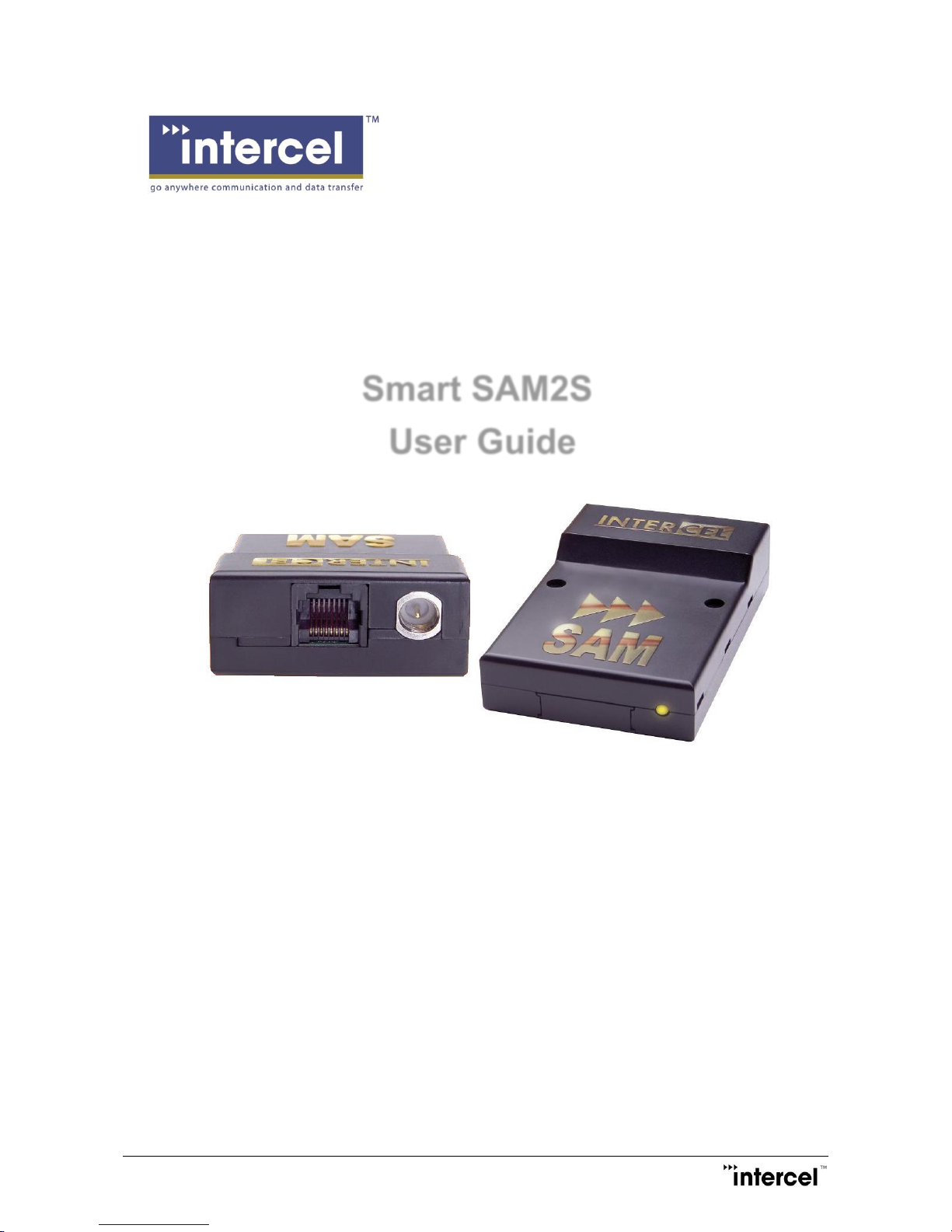
Smart SAM2S
User Guide
Page 2

Smart SAM2S User Guide V1.4
II
Ver1.4
Revision History
Version
Modified By
Date
Description
1.0 18/04/2012
Initial version
1.1 19/06/2013
Update
1.2 09/10/2013
New Packaging Information
1.3 25/11/2014
Software Update
1.4 27/01/2015
Added AT$LGSMS
Page 3

Smart SAM2S User Guide V1.4
1
Ver1.4
Contents
1 Introduction ..........................................................................................................................................................2
2 Safety Precautions .............................................................................................................................................3
3 Radio Frequency Exposure - SAR ...................................................................................................................4
4 WEEE Directive 2002/96/EC, Disposal Of Old Electronic Equipment .......................................................5
5 Packaging ............................................................................................................................................................6
5.1 Contents ............................................................................................................................................................6
5.2 The Packaging Box ..........................................................................................................................................6
5.3 The Production Label ......................................................................................................................................7
6 Functionality ........................................................................................................................................................8
6.1 General ..............................................................................................................................................................8
6.2 RJ45 Socket ......................................................................................................................................................9
6.3 FME-Male 50Ω Antenna Connector ..............................................................................................................9
6.4 SIM Holder ........................................................................................................................................................9
6.5 LED Status ........................................................................................................................................................9
6.6 Data Cable ......................................................................................................................................................10
7 Electrical Characteristics .................................................................................................................................11
7.1 Power Consumption ......................................................................................................................................11
7.2 RF Bands ........................................................................................................................................................11
7.3 Receive Sensitivity .........................................................................................................................................11
7.4 Conducted Transmit Power ..........................................................................................................................11
7.5 Main Antenna Specifications ........................................................................................................................12
7.6 Environmental Characteristics .....................................................................................................................12
8 The Smart SAM2S TCP/IP Operation ...........................................................................................................13
8.1 Communication Sockets ...............................................................................................................................13
8.2 TCP/IP AT$ Commands ..............................................................................................................................14
8.3 CSD Call Escape Sequence .......................................................................................................................21
9 Firmware Upgrade ...........................................................................................................................................22
9.1 Firmware Upgrade for the 2G Module ........................................................................................................22
9.2 Firmware Upgrade for the Cortex M3 ARM Processor.............................................................................22
Page 4
Smart SAM2S User Guide V1.4
2
Ver1.4
1 Introduction
The Smart SAM2S is a compact, light-weight, GSM/GPRS based modem. It provides GSM and GPRS
connectivity. The Smart SAM2S comes in 2 selectable options:
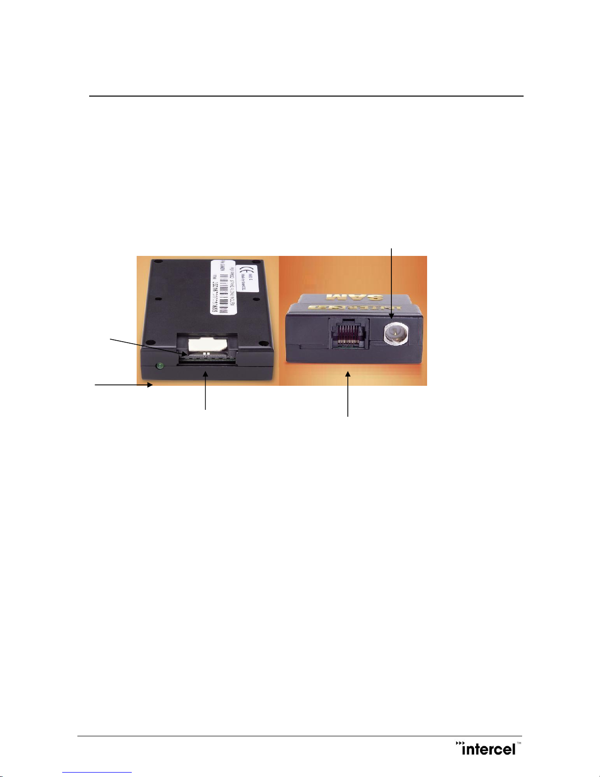
The Smart SAM2S is designed for both mobile and fixed M2M applications. It has an RJ45 socket for input
voltage and the serial RS232 signals, an FME-male for antenna connection, a SIM holder and an LED
indicator.
The Smart SAM2S is capable of sending/receiving SMS; Circuit switched data and Packet-switched data.
FME-Male antenna connector
SIM holder
LED indicator
STD-Link
RJ45 socket for input power and serial RS232
Mobile station engine MC52i
EU approval CE-0682
GCF-CC Version 3.27.1
A-tick
Page 5

Smart SAM2S User Guide V1.4
3
Ver1.4
2 Safety Precautions
The following safety precautions must be observed whenever the Smart SAM2S modem is in operation or in
service. Failure to comply with these precautions violates the safety standards of the design, manufacture
and intended use of the product
- Switch off the Smart SAM2S modem :
In hospitals or places where medical equipment may be in use.
In an aircraft
Refueling points
Explosive areas
- Restricted use of the Smart SAM2S modem
Near any chemical plant
Near any fuel depot
Areas with mobile phone warning signs
Respect national regulations on the use of cellular devices.
The Smart SAM2S modem receives and transmits radio frequency energy while switched on, therefore
interference can occur if the Smart SAM2S is near TVs, radios, PCs or any inadequately shielded
equipment.
Page 6

Smart SAM2S User Guide V1.4
4
Ver1.4
3 Radio Frequency Exposure - SAR
The Smart SAM2S modem is a low-power transceiver, similar to a typical handheld GSM/GPRS mobile
phone. When it is turned on, it will emit low-level radio frequency energy.
There are different guidelines and standards around the world that govern the permitted levels of radio
frequency exposure for general population. The levels include a safety margin to a human body.
The Specific Absorption Rate (SAR) is a measure of the rate at which radio frequency energy is absorbed by
the body when exposed to radio frequency electromagnetic field. The SAR value is determined at the highest
certified power level in the laboratory conditions, but the actual SAR level of the transceiver while operating
can be well below this value. This is because the transceiver is designed to use minimum power to connect
to the network.
The Smart SAM2S modem is approved to use in applications where the antenna is placed more than
21cm from the body.
For other applications, the integrator is responsible for the local SAR requirements.
Page 7

Smart SAM2S User Guide V1.4
5
Ver1.4
4 WEEE Directive 2002/96/EC, Disposal Of Old
Electronic Equipment
This symbol on the product indicates that this product shall not be treated as household waste.
It must be placed at an appropriate collection point for the recycling of electrical and electronic equipments.
By ensuring the correct disposal of this equipment, it will help the environment and human’s health.
Recycling will help to conserve natural resources.
The Smart SAM2S product is RoHS compliant
Page 8
Smart SAM2S User Guide V1.4
6
Ver1.4
5 Packaging
5.1 Contents
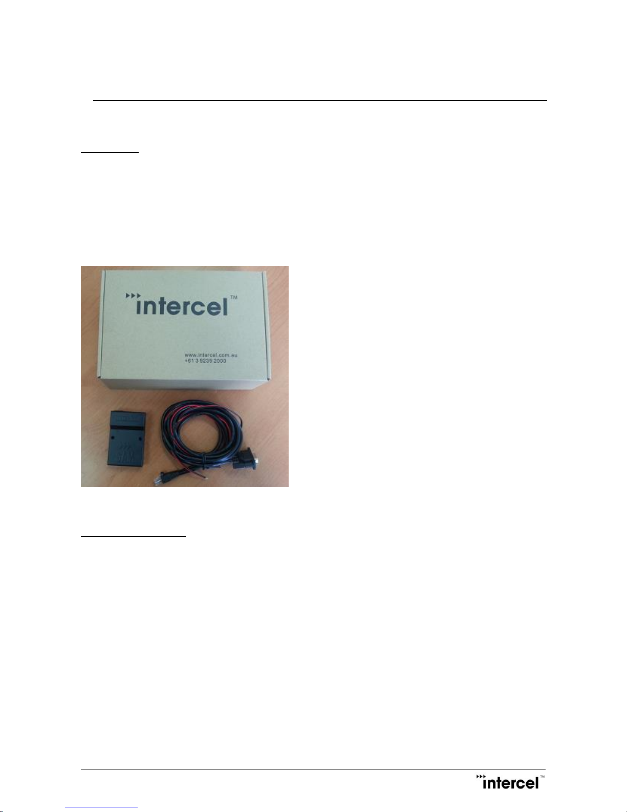
The Smart SAM2S package consists of:
- A Smart SAM2S Modem
- A Data Cable
- A Smart SAM2S User Guide
5.2 The Packaging Box
The carton box dimensions are 230mm x 155mm x 70mm
The data cable is 2m long
The label size is 50mm x 33mm
A power supply is available on request. It is recommended that the Smart SAM2S is powered using a
12Vdc/1A power supply.
Various antenna options are also available on request. Please make sure the correct antenna is used to get
optimised performance from the Smart SAM2S.
Page 9
Smart SAM2S User Guide V1.4
7
Ver1.4
5.3 The Production Label
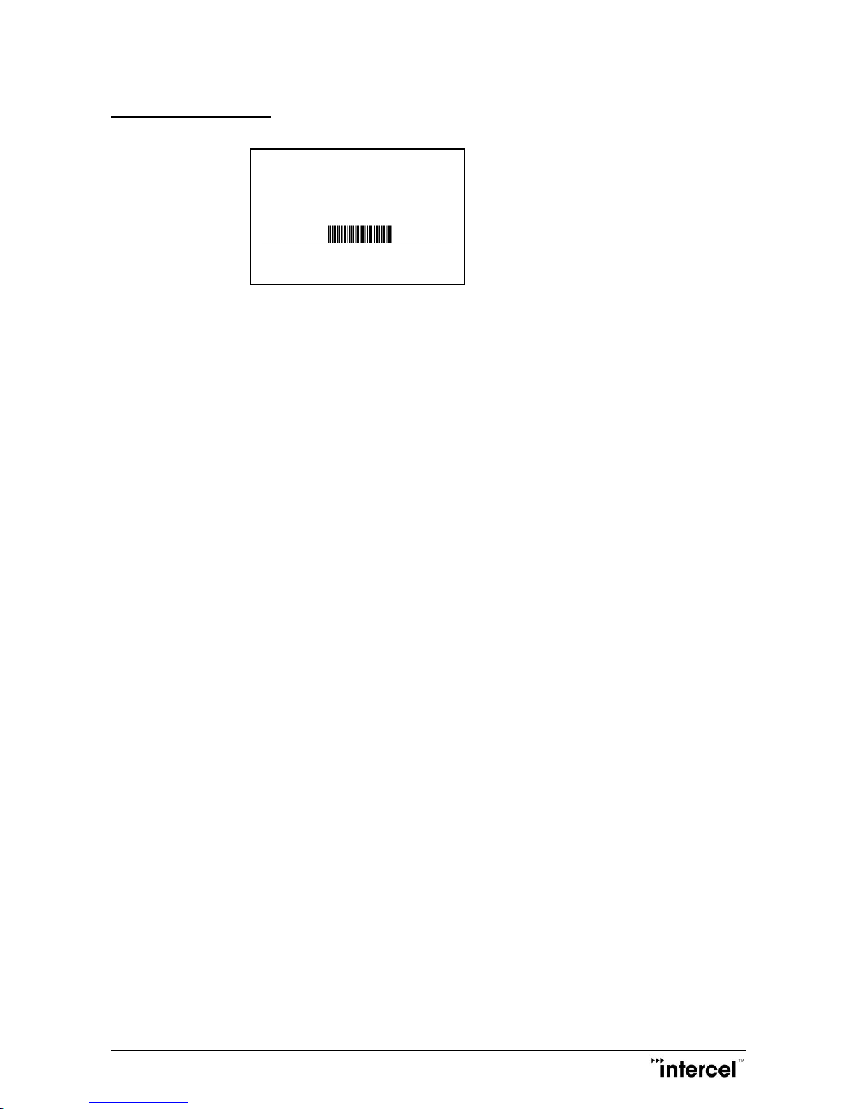
The production part number is located at the back of the Smart SAM2S, which includes:
- The product model
- The software version
- The hardware version
- The IMEI number
- The manufacturer
- The part number
Product Model: Smart SAM2S
Software : Version 1.C
Hardware : Version 1.7
IMEI
352679010 049570
Made by: Intercel Pty Ltd
Page 10
Smart SAM2S User Guide V1.4
8
Ver1.4
6 Functionality
6.1 General
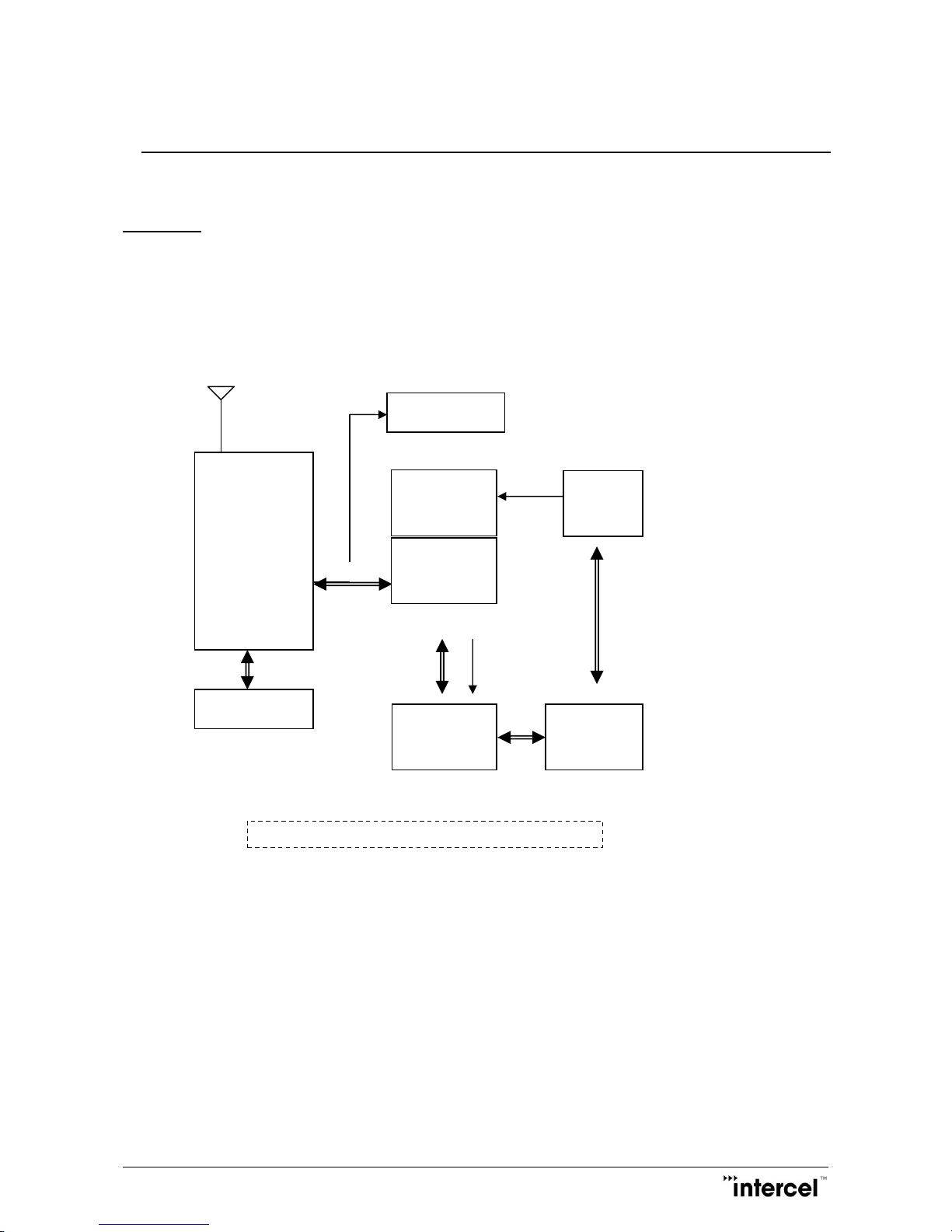
The Smart SAM2S modem consists of an RJ45 socket for serial port and input power, an FME male antenna
connector and a SIM holder. The LED indicator, located next to the SIM holder, indicates the Smart SAM2S
operating status.
FME connector
GSM/GPRS
ENGINE
Switching
Power
Supply
RS232
Serial Data
Interface
SIM Interface
RJ45
Socket
LED Indicator
The Smart SAM2S Functional Block Diagram
uController
Serial Data
switches
Page 11

Smart SAM2S User Guide V1.4
9
Ver1.4
6.2 RJ45 Socket
Pin Signals Description
1 VIN Input Voltage 5Vdc - 32Vdc
2 DCD Data Carrier Detect
3 DTR Data Terminal Ready
4 GND Common Ground
5 RXD Serial Data out of the SAM
6 TXD Serial Data into the SAM
6 CTS Clear to Send
8 RTS Ready to Send
6.3 FME-Male 50Ω Antenna Connector
The FME male antenna connector is a 50Ω impedance antenna connector. The antenna used for the Smart
SAM2S must have 50Ω impedance.
6.4 SIM Holder
The SIM holder is designed to accommodate a mini-SIM card. The SIM card can either be 3V or 1V8 SIM. To
insert the SIM card, remove the door by sliding it back toward the end. Make sure the SIM card faces the
right way as indicated on the box. Voltage levels over this SIM interface complies with 3GPP standards
6.5 LED Status
The LED indication has the following status:
- 600ms on/ 600ms off: No SIM card or no SIM PIN or Network search in progress or Network login in
progress.
- 75ms on/ 3sec off: Idle mode, registered to the GSM network.
- 75ms on/75ms off/75ms on/3sec off: at least 1 GPRS PDP context activated.
- 500ms on/25ms off: Packet-switched data transfer in progress.
- LED is on steady: CSD call is connected
- LED is off permanently : No power
Page 12
Smart SAM2S User Guide V1.4
10
Ver1.4
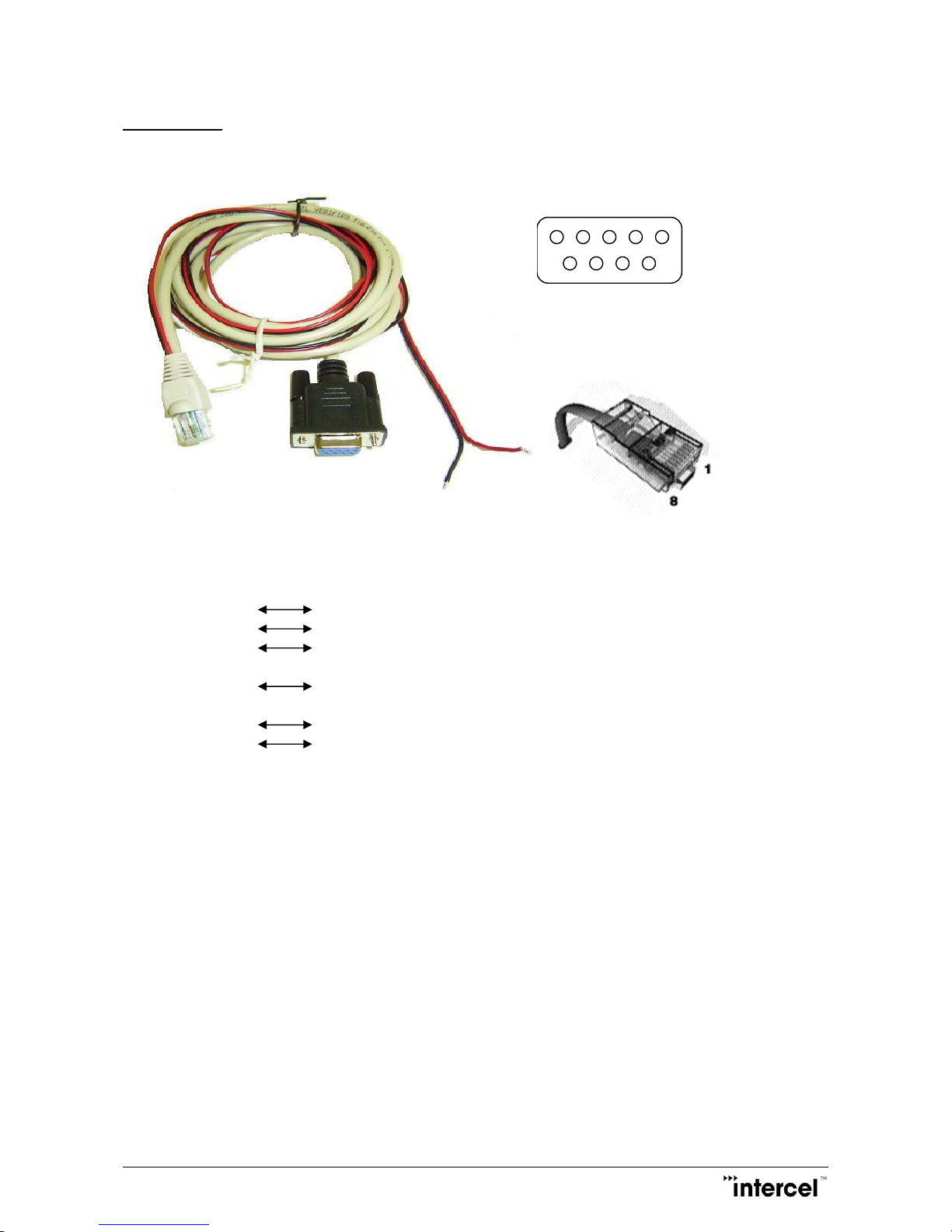
6.6 Data Cable
The data cable is 2m long. It consists of an RJ45 plug, a DB9-female connector and a 2-wire input power.
5 4 3 2 1
9 8 7 6
DB9 Signals RJ45 Description
1 DCD 2 Data Carrier Detect
2 RXD 5 Serial Data out of the Smart SAM2S
3 TXD 6 Serial Data into the Smart SAM2S
4 DTR 3 Not Used
5 GND 4 Common Ground
6 DSR
7 CTS 8 Clear to Send
8 RTS 7 Request to Send
9 RI Not used
1 RED wire: Input voltage from 5Vdc to 32Vdc
4 BLACK wire: Power Ground
Page 13

Smart SAM2S User Guide V1.4
11
Ver1.4
7 Electrical Characteristics
7.1 Power Consumption
Network search 70mA @ 12V
Idle mode 45mA @ 12Vdc
Connected mode 95mA @ 12Vdc
GPRS PSD transfer 250mA @ 12Vdc
Peak current during the 577µs transmission pulse 1.2A @ 12V
7.2 RF Bands
EGSM900 : Tx = 880MHz - 915MHz, Rx = 925MHz - 960MHz
DCS1800 : Tx = 1710MHz - 1785MHz, Rx = 1805MHz - 1880MHz
7.3 Receive Sensitivity
Band Typical Rx Sensitivity Maximum Rx Sensitivity
(dBm) (dBm)
EGSM900 (2% ber) CS -102 -107
DCS1800 (2% ber) CS -102 -107
Note:
- Bit error rate < 2.4%
7.4 Conducted Transmit Power
Parameter Min Typical Max
GSM900 +31dBm +33dBm +35dBm
DCS1800 +28dBm +30dBm +32dBm
Page 14

Smart SAM2S User Guide V1.4
12
Ver1.4
7.5 Main Antenna Specifications
Max cable loss 0.5dBm
Impedance 50Ω
Max allowed VSWR 3:1
The maximum antenna gain recommended for consideration against RF exposure and ERP/EIRP limits, is:
- In Cellular band : 5dBi
- In PCS band : 4dBi
7.6 Environmental Characteristics
Operating temperature -40°C to +75°C
Storage temperature -40°C to +90°C
Humidity 90% relative humidity (non-condensing)
Page 15

Smart SAM2S User Guide V1.4
13
Ver1.4
8 The Smart SAM2S TCP/IP Operation
The Smart SAM2S has a MCU (Microcontroller) to control the 2G module PHS8-P, the Smart SAM2S can be
operating in there different modes, defined by parameter SAMMODE:
-SAMMODE=0, modem is in dumb mode, when power on the MCU turn on the 2G module, check its baud
rate, turn on LED and release control of the 2G module to the connecting device, AT commands can be send
from serial port here after, the MCU keep monitor the 2G module Rx pin for AT$ commands and check time
in the POLLPERIOD parameter (to reset itself and the 2G module.
-SAMMODE=1, modem is in GPRS or PSD (Packet Switch Data) smart mode, the MCU is in total control of
the 2G module, on power up the software reads all parameters from flash and activates a GPSR connection,
it then creates an UDP and a TCP socket to listen for data transfer connection, opens an UDP and a TCP
socket to listen for remote AT commands connection, if programmed as TCP client it will tries to connect to
a remote TCP server, the modem then stays in GPRS online idle state waiting for CSD call, SMS, UDP data
or TCP connection, the software maintains GPRS connectivity by the mean of IP TRACE using
POLLPERIOD parameter stored in flash.
-SAMMODE=2, modem is in CSD (Circuit Switch Data) smart mode, this mode is used if SIM card is not
setup for GPRS, MCU is in total control of the 2G module, modem is always in waiting for CSD call or SMS.
The modem supports DDNS, for SIM card that has dynamic public IP address the software can performs
dynamic DNS updating to a DNS server (supporting dyndns.com and noip.com).
The modem provides security for remote management by keeping a list of SMS sending mobile numbers, a
list of CSD calling numbers, a list of PSD sending IP addresses and username and password login,
password data is encrypted for remote transaction.
8.1 Communication Sockets
TCP Data: Socket connection allows transparent data to pass through from host computer to the modem
serial port and vice versa, this operation is similar to the CSD data communication, in TCP
server mode the socket will be disconnected after 5 minutes of no data transfer.
UDP Data: Socket connection allows transparent data to pass through from host computer to the modem
serial port and vice versa, this operation is similar to the CSD data communication, a block
of data received from a remote UDP server will open a 2 minutes window for data to be
transfer from the serial port.
TCP AT Command: Socket connection allows a user from the host computer to send AT commands to
the modem and receive its responses, socket will be disconnected after 5 minutes of no
activity, and socket also can be used for remote firmware update.
Page 16

Smart SAM2S User Guide V1.4
14
Ver1.4
UDP AT Command: Socket connection allows a user from the host computer to send AT commands to
the modem and receive its responses, and socket also can be used for remote firmware
update.
.
8.2 TCP/IP AT$ Commands
Communications parameters are stored in Flash using AT$PARAMETERS.
Parameters are defined as:
APN=Access Point Name
USERNAME=Username that may required with GPRS login
PASSWORD=Password that may required with GPRS login
LTCPPORT=Local TCP listening port
RTCPIP=Remote TCP server IP
RTCPPORT= Remote TCP server port
TCPMODE=0 or 1 (0 disable modem TCP client, 1 enable modem TCP client)
LUDPPORT=Local binding UDP port (modem listen for UDP data on this port)
RUDPIP=Remote binding UDP IP (modem only accept data from this IP)
RUDPPORT=Remote binding UDP port (modem send UDP data to this port)
POLLPERIOD=Modem use this time to send TRACE packet to check for GPRS connectivity.
SBREAKTIME=Serial port break time, modem will wait for this break in serial port transmission before
packetize the data and send.
MBREAKTIME=Modem or GSM module serial break time, use to adjust the way the modem rebuild long IP
packet from fragments of CMUX frames.
BAUDRATE=Serial port baud rate.
DATALEN=Serial port data bits 7 or 8
PARITY= NONE or ODD or EVEN
SAMMODE=0 for standard modem, 1 for PSD mode, 2 for CSD mode.
All parameters can be programmed all at once.
Page 17

Smart SAM2S User Guide V1.4
15
Ver1.4
AT$PARAMETERS=APN=telstra.extranet,USERNAME=intercel,PASSWORD=mach,LTCPPORT=10000,RT
CPIP=203.45.1.236,RTCPPORT=10000,TCPMODE=,LUDPPORT=20000,RUDPIP=203.45.1.236,RUDPPO
RT=20000,POLLPERIOD=60,SBREAKTIME=100,MBREAKTIME=5,BAUDRATE=115200,DATALEN=8,PAR
ITY=NONE,SAMMODE=0
Saved parameters to flash...
OK
Or a few parameters or one at a time.
AT$PARAMETERS=APN=telstra.extranet,USERNAME=intercel,PASSWORD=mach
Saved parameters to flash...
OK
AT$PARAMETERS=LTCPPORT=10000,RTCPIP=203.45.1.236,RTCPPORT=10000,TCPMODE=,LUDPPO
RT=20000,RUDPIP=203.45.1.236,RUDPPORT=20000
Saved parameters to flash...
OK
AT$PARAMETERS=POLLPERIOD=60,SBREAKTIME=100,MBREAKTIME=5,BAUDRATE=115200,DATALE
N=8,PARITY=NONE
Saved parameters to flash...
OK
AT$PARAMETERS=SAMMODE=0
Saved parameters to flash...
OK
AT$PARAMETERS?
$PARAMETERS:
APN: telstra.extranet
USERNAME: intercel
PASSWORD: mach
LTCPPORT: 10000
RTCPIP: 203.45.1.236
RTCPPORT: 10000
TCPMODE: 0
LUDPPORT: 20000
RUDPIP: 203.45.1.236
RUDPPORT: 20000
Page 18

Smart SAM2S User Guide V1.4
16
Ver1.4
BAUDRATE: 115200
DATALEN: 8
PARITY: NONE
POLLPERIOD: 60
SBREAKTIME: 100
MBREAKTIME: 5
SAMMODE: 0
OK
AT$UDPCONNECT
If modem is already allocated an IP address, this command will put the modem in UDP data mode,
modem DCD pin go high, data from serial will be packetized into UDP packet and send to remote
UDP server (UDP settings must be set prior), modem will return to AT Command mode if it
receiving no UDP data in 30 seconds.
If modem has no IP address (CSD mode or SAMMODE=2), the modem will connect to PSD and go
into UDP data mode, modem DCD pin go high, data from serial will be packetized into UDP packet
and send to remote UDP server (UDP settings must be set prior), modem will reset and return to
CSD mode if it receiving no UDP data in 30 seconds.
AT$TCPCONNECT
If modem is already allocated an IP address, this command will make a TCP client connection to
the remote TCP server, modem will return to AT Command mode if it receives no TCP ACK in 30
seconds.
If modem has no IP address (CSD mode or SAMMODE=2), the modem will connect to PSD and
make a TCP client connection to the remote TCP server, modem will reset and return to CSD mode
if it receives no TCP ACK in 30 seconds.
AT$DDNS
Use to setup parameters required for Dynamic DNS updating.
Parameters are defined as:
DDNSENABLE= 0 or 1 (0 disable, 1 enable)
DDNSHOST=Host name
DDNSUSERNAME=DNNS account name
DDNSPASSWORD=DDNS account password
Page 19

Smart SAM2S User Guide V1.4
17
Ver1.4
DDNSSERVER=DDNS server
DDNSSTRING: Only need to change from default in some circumstances with Intercel support
DDNSAUTH: Only need to change from default in some circumstances with Intercel support
DDNSAGENT: Only need to change from default in some circumstances with Intercel support
PDNSIP=Primary DNS, leave blank if not using your own DNS server, not a requirement for DDNS.
SDNSIP=Secondary DNS, leave blank if not using your own DNS server, not a requirement for DDNS
DNSTTL= DNS Time To Live in minutes before updating of DNS entries, not a requirement for DDNS.
AT$DDNS=PDNSIP=8.8.8.8,SDNSIP=8.8.4.4,DNSTTL=240,DDNSENABLE=0,DDNSHOST=intercelau.ddns
.net,DDNSUSERNAME=intercelau,DDNSPASSWORD=123456789,DDNSSERVER=dynupdate.noip.com,D
DNSSTRING=GET/nic/update?hostname=%s&myip=%sHTTP/1.0,DDNSAUTH=Authorization:
Basic%s,DDNSAGENT=User-Agent:SAM2S/1.0 [email protected]
Saved parameters to flash...
OK
AT$DDNS?
$DDNS:
DDNSENABLE: 0
DDNSHOST: intercelau.ddns.net
DDNSUSERNAME: [email protected]
DDNSPASSWORD: 123456789
DDNSSERVER: dynupdate.no-ip.com
DDNSSTRING: GET /nic/update?hostname=%s&myip=%s HTTP/1.0
DDNSAUTH: Authorization: Basic %s
DDNSAGENT: User-Agent: SAM2S/1.0 [email protected]
PDNSIP: 8.8.8.8
SDNSIP: 8.8.4.4
DNSTTL: 240
OK
AT$DDNSTEST
Use to force a manual updating of IP to the DDNS server, all required parameters must be set beforehand.
AT$DDNSTEST
$DDNSTEST: Starting....
$DDNSTEST: Resolving dynupdate.no-ip.com....
Page 20

Smart SAM2S User Guide V1.4
18
Ver1.4
Connecting to DDNS dynupdate.no-ip.com ....
Connected to DDNS dynupdate.no-ip.com
HTTP/1.1 200 OK
Date: Tue, 02 Sep 2014 00:33:32 GMT
Server: Apache/2
Content-Location: update.php
Vary: negotiate
TCN: choice
Content-Length: 19
Connection: close
Content-Type: text/plain; charset=UTF-8
good 123.209.169.62
DDNS host intercelau.ddns.net updated with 123.209.169.62
OK
AT$ACCESS
Use to setup parameters required for remote access.
Parameters are defined as:
IPBLOCK=0 or 1 (0 disable, 1 enable remote IP access from REMOTEIP1-REMOTEIP4)
REMOTEIP1= nnn.nnn.nnn.nnn
REMOTEIP2= nnn.nnn.nnn.nnn
REMOTEIP3= nnn.nnn.nnn.nnn
REMOTEIP4= nnn.nnn.nnn.nnn
SMSBLOCK=0 or 1 (0 disable, 1 enable remote SMS access from REMOTESMS1-REMOTESMS4)
REMOTESMS1= ccnnnnnnnnn cc for country code
REMOTESMS2= ccnnnnnnnnn
REMOTESMS3= ccnnnnnnnnn
REMOTESMS4= ccnnnnnnnnn
DIALBLOCK= 0 or 1 (0 disable, 1 enable remote dialling access from REMOTEDIAL1-REMOTEDIAL4)
REMOTEDIAL1= acnnnnnnnn ac for area code
REMOTEDIAL2= acnnnnnnnn
REMOTEDIAL3= acnnnnnnnn
REMOTEDIAL4= acnnnnnnnn
Page 21

Smart SAM2S User Guide V1.4
19
Ver1.4
AT$ACCESS=IPBLOCK=1,REMOTEIP1=10.64.24.2,REMOTEIP2=,REMOTEIP3=,REMOTEIP4=,SMSBLO
CK=1,REMOTESMS1=0413586218,REMOTESMS2=,REMOTESMS3=,REMOTESMS4=,DIALBLOCK=1,R
EMOTEDIAL1=0395612959,REMOTEDIAL2=,REMOTEDIAL3=,REMOTEDIAL4=
Saved parameters to flash...
OK
AT$ACCESS?
$ACCESS:
IPBLOCK: 1
REMOTEIP1: 10.64.24.2
REMOTEIP2:
REMOTEIP3:
REMOTEIP4:
SMSBLOCK: 1
REMOTESMS1: 0413586218
REMOTESMS2:
REMOTESMS3:
REMOTESMS4:
DIALBLOCK: 1
REMOTEDIAL1: 0395612959
REMOTEDIAL2:
REMOTEDIAL3:
REMOTEDIAL4:
OK
AT$LGSMS
Use to program parameters for last gasp SMS.
Parameters are defined as:
LGSMSMSG=SMS message text, default is "SAM2S low power detected...”
LGSMSNO=SMS phone number
AT$LGSMS= LGSMSMSG= SAM2S power supply is low...., LGSMSNO=+61418505361
Saved parameters to flash...
OK
AT$LGSMS?
$LGSMS:
LGSMSMSG: SAM2S power supply is low....
Page 22

Smart SAM2S User Guide V1.4
20
Ver1.4
LGSMSNO: +61418505361
OK
AT$LOGIN
Use to setup login details for remote sending of AT commands, parameters and software updating; password
is encrypted so remote login required PC software SAM2S Terminal.
AT$LOGOFF
Use to log off remote access instantly; modem will lock out remote access that has been idled for 120
seconds.
AT$IP
Use to return the allocated IP address of the current GPRS connection
AT$IP
$IP: 123.209.157.9
OK
AT$VERSION
This command returns the TCP/IP software version.
AT$VERSION
SAM2S V2.1 22/12/14 13:54
OK
AT$RESET
Use to remotely reset the modem, normally after sending of new parameters
Page 23

Smart SAM2S User Guide V1.4
21
Ver1.4
AT$RESET
SAM Reset...
OK
AT$SMSTOSERIALON
This command allows the connecting device to receive SMS notification for 300s: e.g. “+CMTI: "SM",1”,
the connecting device must send AT+CMGR to read SMS and AT+CMGD to delete it, during this
300s period, modem will not able to decode AT$ commands sending to it over SMS.
8.3 CSD Call Escape Sequence
During CSD call to the Smart SAM2S modem, send three consecutive EscEscEsc or hex number
sequence 0x1B 0x1B 0x1B to switch the modem between data mode and remote AT commands mode.
Notices
-In SAMMODE=0, after power on the MCU turns on the 2G module, checks its baud rate, turns on LED
before releases control of the 2G module to the connecting device, all this take between 5 to 10 seconds,
so the modem is only ready for AT commands here after.
-In SAMMODE=1, the modem take 30 to 60 seconds to connect to GPRS, modem only response to AT
commands from serial port once it is connected to GPRS or after it has failed , if it failed to connect it
will reset after 120 seconds.
-In SAMMODE=2, the MCU take about 20 seconds to set up the 2G module , the modem only response to
AT commands from serial port after setting up is finished.
-In SAMMODE 1 and 2 if the Smart SAM2S modem is powered up without a SIM card it will go into AT
command mode after 20 seconds.
The parameter POLLPERIOD which keep the time in minute which when expired will reset the modem if
SAMMODE=0 or SAMMODE=2, if SAMMODE=1 for PSD mode the modem will use this time to send
TRACE IP packet to check for network connectivity.
-In SAMMODE=1 and 2 the modem can be reset remotely by calling the voice number.
Page 24

Smart SAM2S User Guide V1.4
22
Ver1.4
9 Firmware Upgrade
9.1 Firmware Upgrade for the 2G Module
The module’s firmware can be upgraded over the serial or USB port using the dedicated Upgrade Program
running on PC, if using USB ,the 2G module’s driver must be installed on the PC beforehand.
9.2 Firmware Upgrade for the Cortex M3 ARM Processor
The processor’s firmware can be upgraded over the serial port or JTAG port using the LM Flash Programmer
running on PC.
Firmware and parameters can be upgraded over the serial port, GPRS, CSD or SMS (parameters only)
using SAM3X Terminal program running on PC.
Page 25

Smart SAM2S User Guide V1.4
23
Ver1.4
Notes
Page 26

Smart SAM2S User Guide V1.4
24
Ver1.4
Contact Information
Australia (Headquarters)
33 Glenvale Crescent
Mulgrave 3170
Victoria, Australia
Ph: +61 (0)3 9239 2000
Fx: +61 (0)3 9561 2614
Email: [email protected]
Internet: www.Intercel.com.au
New Zealand
For New Zealand Customers
Toll Free No: 0800 742 600
United Kingdom
5 Elstree Gate
Elstree Way
Borehamwood
Hertfordshire
WD6 1JD
Email: [email protected]
Hong Kong
Unit 6, 17th Floor
Vanta Industrial Centre
21-33 Tai Lin Pai Road
Kwai Chung, New Territories
HKSAR of the PRC
Ph: +852 2362 9018
Fx: +852 2648 8806
Shenzhen
Room 1303, 13/F, West Wing
Tian’an High-Tech Plaza Phase II
Tian’an Cyber Park
Futian, Shenzhen
China
Ph: +86 755 8835 3778
Fx: +86 755 8835 2489
The information in this document is believed to be accurate in all respects at the time of publication but is subject to
change without notice. intercelTM assumes no responsibility for errors and omissions, and disclaims responsibility for
any consequences resulting from the use of information included herein. Additionally, intercelTM assumes no
responsibility for the functioning of undescribed features or parameters. intercelTM reserves the right to make changes
without further notice. intercelTM makes no warranty, representation or guarantee regarding the suitability of its
products for any particular purpose, nor does intercelTM assume any liability arising out of the application or use of any
product or circuit, and specifically disclaims any and all liability, including without limitation consequential or
incidental damages. intercelTM products are not designed, intended, or authorized for use in applications intended to
support or sustain life, or for any other application in which the failure of the intercelTM product could create a
situation where personal injury or death may occur. Should Buyer purchase or use intercelTM products for any such
unintended or unauthorized application, Buyer shall indemnify and hold intercelTM harmless against all claims and
damages.
 Loading...