

Page 1
Program U ser Settings
press 0 - 9 for other entries.
Press 1 fo r O F F ; press 2 fo r O N ;
Press # to select option or accept entry.
06
07
05
04
13
14
12
11
Arm to STAY
Q u ic k G u id e
D isarm Sy stem /C a n cel A larm
if desired.
2
01
02
03
3
1
08
09
10
Press to deselect option or cancel entry.
Close all protected doors and windows.
Press 3 + C O D E .
Exit premises through delay door.
2
3
1
Press 2 + C O D E .
Close all protected doors and windows.
Press 4 to arm d elay do o rs instantly,
Arm to AWAY
Zone/Sensor Num ber
Press 1 + C O D E .
2
1
Press A o r B to scro ll through m e nu s.
M ake sure system is disarm ed .
2
1
Press 7 + 1 to turn C H IM E on or off.
M ake sure system is disarm ed .
2
1
Turn CH IM E O n/O ff
Press BYPASS + CO D E + Sensor N o.
Arm system to desired lev el.
Bypass Sensors
Touchpad Panic
Zones
OPELCI
Bypassed
Open
Trouble
No Delay
Chime
AC Failure
XXXUAA UAU
EA O
RIAIL YRLIIA YRLIIA Y
R
RIFRFIRFIALEEE
MEMM YR
Press Status
Enter Code
System Arm ed to
PROG. Test
Supervisory
System is OK
ReceiverPhone
Bu s Fa ilu re
CPU Low Batt
Status
Features
press both
Lights
System
Away
Pager
Off
No Delay
press both
press both
Test System W ee kly
S ile n t
Stay
D
*
7
0#
8
B
A41
5
6
2
3
Bypass
Menu
C
9
Armed
Ready
Document Number: 466-1668 Rev . B
August 2000
ITI Part No. 60-820
Installation Instructions
Product Summary
The SuperBus 2000 Fixed Display Touchpad lets users
operate a Concord
2.0 or newer) security system and change user
programmable settings.
The display provides messages to system users that indicate
system status during system operation and data-entry feedback while in user-programming mode. Display background brightness can be adjusted to accommodate for
lighting conditions at the touchpad location.
Two LEDs provide arming and system trouble status. Refer
to the specific panel User’s Guide/Owner’ s Manual for LED
function information.
A built-in speaker provides status and alarm tones. Chime
and trouble beep tone frequency (pitch) can b e changed to a
more desirable or distinct tone, and to compensate for hearing impaired persons.
Police, fire, and auxiliary panic buttons can be activated
anytime in case of an emergency.
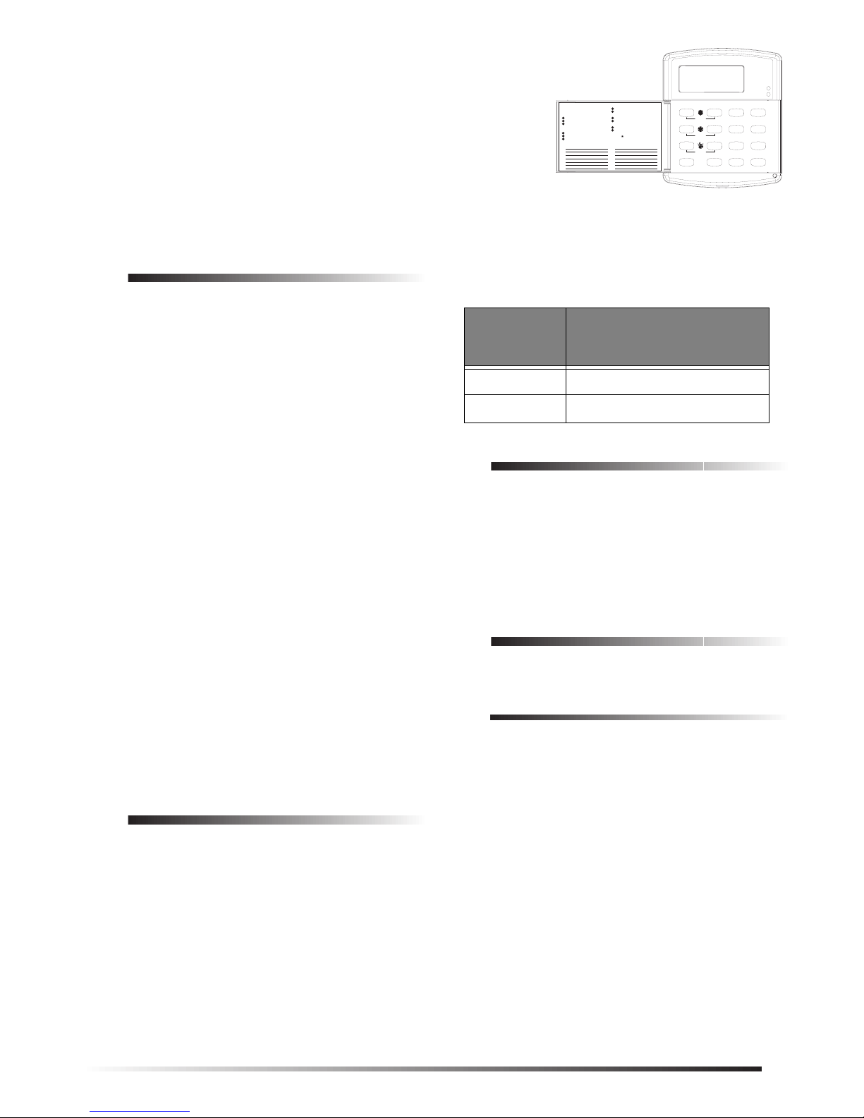
A label on the inside of the touchpad door provides users
with basic system commands for quick and easy reference
of system operation and user programming.
Each touchpad is preset from the factory with an ID number
(SuperBus 2000 technology), eliminating DIP switch
settings and speeding up installation.
Note
This touchpad cannot be used for installer programming. You must conne ct an al phan umeric tou chpad to
the panel to perform on-site programming, or use
ToolB ox Downloader (software version 5.1 or newer).
Express or Concord (software version
Installation Guidelines
❑ Follow the maximum wire length guidelines in Table 1.
Table 1. Maximum Touchpad Wire Lengths
Wire Gauge
(Unshielded
or Shielded)
Maximum Wire Length
Between Touchpad and
Panel
18 750 feet
22 300 feet
Tools and Equipment Needed
❑ 4-conductor, 22- or 18-gauge wire
❑ Screwdrivers
❑ Drill with bits
❑ #6 screws and anchors (included)
❑ Panhead screws for a gang box installation
❑ Saw or utility knife for cutting wallboard
Installation
This section describes touchpad mounting and wiring.
Installing the Mounting Plate
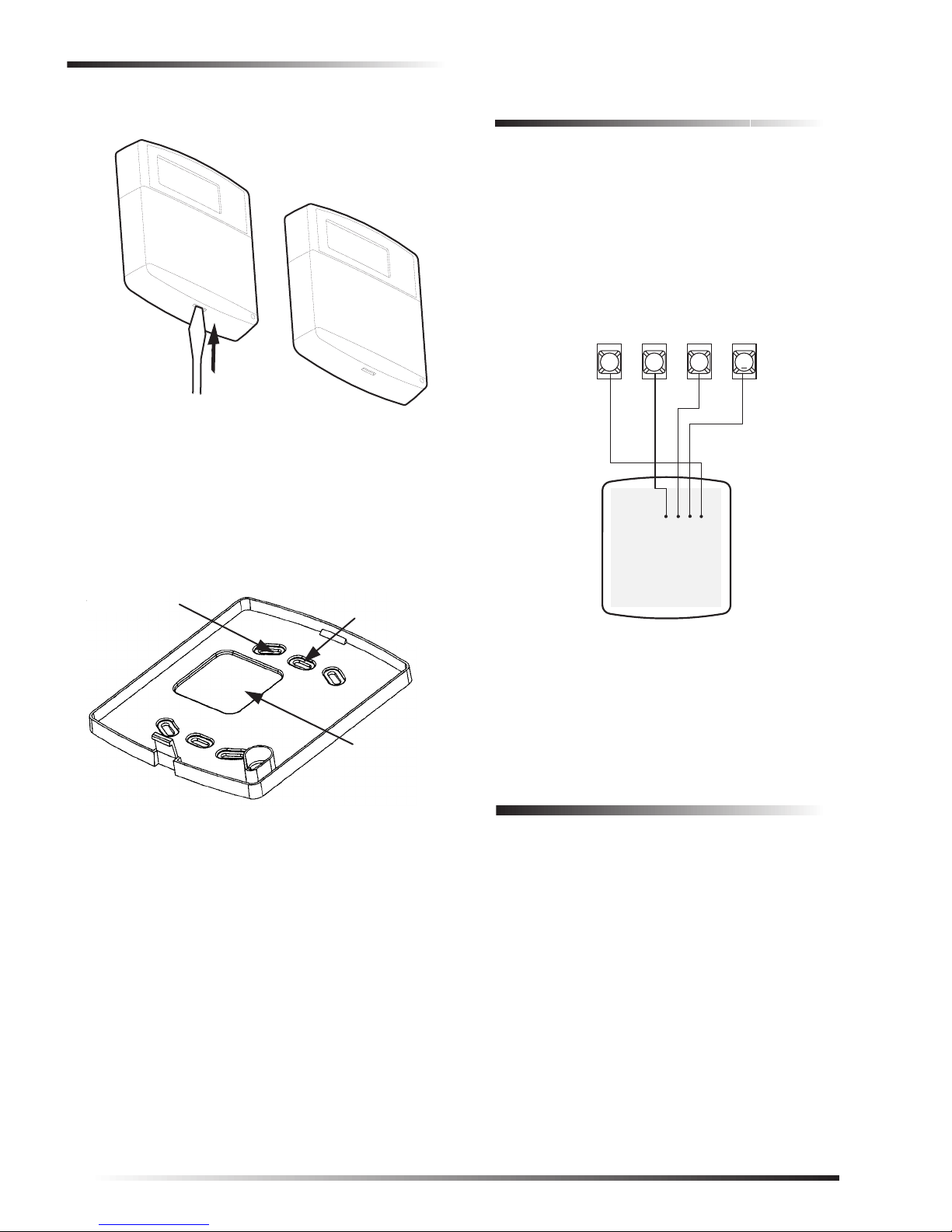
1. Insert the blade of a small screwdriver at the top of the
slot, located on the bottom of the touchpad and gently
press down until the mounting pl at e separ at es from the
touchpad (see Figure 1).
❑ Mount the touchpad in an environmentally controlled
area (32°F to 120°F) (0°C to 49°C).
❑ For Concord Express systems, up to 4 bus devices can
be connected to the panel.
❑ For Concord (software versions 2.0 and newer), up to
16 bus devices can be connected to the panel.
❑ Maximum current draw of the touchpad is
65 mA.
❑ Minimum current draw of the touchpad when the panel
is operating on backup battery only, is 11 mA.
❑ Do not exceed the maximum available panel power
when using panel power for bus devices and hardwire
detectors (see specific panel Installation Instructions).
1
Page 2
Power Up and Bus Communication
T
INSERT
SCREWDRIVER
Figure 1. Separating the Touchpad from the Mounting
Plate
8666G01A.DSF
Wiring
1. Remove panel AC power and disconnect the backup
battery.
2. Run a 4-conductor , 18- to 22-gau ge wire from the panel
to the touchpad location.
3. Splice the 4-conductor cable wires to the red, black,
green, and white wires located on the back of the
touchpad.
4. Connect the touchpad to the panel terminals as shown
in Figure 3.
+12V
GND
3 4 5
A
BUS
B
6
2. Remove the mounting plate and set the touchpad aside.
3. Place the mounting plate on the wall and mark the four
mounting holes (see Figure 2).
WALL- OR
DUAL-GANG
MOUNTING
HOLES (4)
Figure 2. Marking the Mounting Holes
SINGLE-GANG
MOUNTING
HOLES (2)
WIRE ACCESS
AREA
8666G02A.DSF
4. Drill holes and insert anchors at marked locatio ns
where studs are not present.
5. Align the mounting plate wall-moun t holes with the
wall anchors and secure the back-plate to the wall using
the screws provided.
If installing the back-plate on an electrical gang box,
align the appropriate gang box holes and secure the
back-plate to the gang box using the panhead screws
provided.
Note
Do not ove rtighten screws or t he back-p late ma y ben d
and prevent the touchpad from mounting properly.
6. For wall-mounted installations, cut a hole in the wall in
the wire access area of the mounting plate to pull your
cable through for wiring.
BACK OF
OUCHPAD
Figure 3. Wiring the Touchpad to the Panel
+12V/RED
BUS A/GREEN
BUS B/WHITE
GND/BLACK
8666G09A.DSF
5. Set the top of the touchpad on top of the mounting plate
(so it hangs), then press inward on the bottom portion
of the touchpad until you hear the bo ttom latch click
into place.
Po wer Up and Bus
Communication
After making all wiring connections from the touchpad to
the panel, you are ready to power up the panel and verify
correct communication between the touchpad and the panel.
Upon power up, the panel scans the bus for connected
devices and automatically learns the unit number of each
bus device.
Note
If you plan on in stalli ng sy stem s with no al phan umeric
touchpads, it is recomme nded tha t y ou k eep an alphanumeric touchpad with you, specifically for installer
programming. This touchpad can be quickly connected and disconnected from the header pins on the
lower-left portion of the panel, just above the terminal
strip.
2
Page 3

Testing
Note
To power up the panel and verify bus
communication:
1. V erify that all wiring between the panel and touchpad is
correct.
2. Connect the panel battery and plug in the panel transformer. The touchpad should display BUS SCAN, then
show a time display with the PRESS ST ATUS p rompt i n
the upper-left corner.
Note
If the touchpad does not po w e r up (show any displa y )
or respond as described above, unplug the panel AC
transformer and disconnect the backup battery.
Proceed to the “Troubleshooting” section.
Testing
Use the following procedures to test the touchpad for display function, button function and system operation.
To test touchpad display function:
Press and hold the
about three seconds, then release them.
The touchpad cycles through all text messages, then
returns to the time display.
To test button function:
4, 5, and 6 buttons together for
Adjusting Display Brightness
The background lighting (provided by yellow LEDs) of
each touchpad can be adjusted individually to help compensate for lighting conditions at the tou c hpad location. The
brightness adjustment lightens or darkens the display background and button lighting.
To adjust display background brightness:
1. Enter user programmin g mode by press ing
master CODE. The displa y shows
SYSTEM MENU, then TIME - dATE.
2. Press
3. Press
4. Enter a setting from 0 (LEDs off) to 3 (brightest), then
5. Exit user programming by pressing
A or B until the display shows OPTIONS, then
press ƒ. The display shows dOWnLd ON.
A or B until the display shows BRIgHT 2
(default setting).
ƒ. The display shows the new setting.
press
❑
‚ + 4 + ƒ for Concord Express panels,
‚ + 00 + ƒ for Concord panels.
❑ or
9 + system
Changing Chime and Trouble Beep
Tones
1. Press and hold the
about three seconds, then release them. The display
should go blank .
2. Press each touchpad button to display a string of that
button’s number or letter. For example,
1 1 1 1 1 1 1 1 1 1 1, A A A A A A A A A A A, etc.
Pressing
After about 15 seconds of no touchpad activity, the touchpad returns to the time display.
To test for system operation:
Arm/disarm the system, activate the touchpad panics,
bypass sensors, and turn chi me on/of f t o verify co rrect op eration.
Refer to the panel User’s Guide/Owner’s Manual for com-
plete system operating instructions and user programming
procedures.
‚ displays Es and pressing ƒ displays Fs.
CAUTION
Contact the central monitoring stat ion
alarms, to avoid dispatching local police and fire
departments.
Note
The touchpad panic b ut t ons m us t be enabled in order
to activate them. Please see the panel
Instructions
7, 8, and 9 buttons together for
before
Installation
for more information.
activating
The frequency (pitch) of chime and tr ouble beep ton es from
each touchpad can be adjusted to a more desirable or
distinct tone, and to compensate for hearing impaired persons.
Chime and trouble beep tones sound (using the
default fre que nc y) d uring, or wi thi n 1 5 s ec ond s of a n y
button activity at that specific touchpad.
To change status tone pitch:
1. Press and hold the ‚ and 0 buttons together until you
hear a steady tone, then release the buttons.
2. Press and hold
1 to lower the pitch or press and hold
2 to raise the pitch.
3. Release the button when the desired pitch is heard.
After about 15 seconds of no touchpad activity, the steady
tone stops sounding.
3
Page 4
Troubleshooting
0
Troubleshooting
Table 2 describes what to do if the touchpad does not operate correctly.
Table 2. Troubleshooting
Problem Action/Solution
T o uc h pa d do es n’t
power up (no
display and no
beeps when buttons
are pressed).
T o uch pa d disp l a y
appears blank, but
beeps sound when
buttons are pressed.
1. Check fo r correct wiring
connections at touchpa d
and panel terminals.
2. Make sure panel battery
is connected correctly
and that the panel transformer is plugged i n.
3. Make sure panel transformer is not plugged
into an electrical outlet
controlled by a switch.
Relocate transformer to
an unswitched outlet
location, if necessary.
Check for correct bus wiring
connections (green and white
wires) at touchpad and panel
terminals.
Notices
FCC Part 15 Information to the User
Changes or modificat ions not expressly app roved by Interacti ve Technologies, Inc. can void the user ’s authority to operate the equi pm ent.
FCC Part 15 Class B
This equipment h as be en tes ted an d fou nd t o co mply wit h th e lim its for
a Class B digital device, pursuant to part 15 of the FCC Rules. These
limits are designed to provide reasonable protection against interference
in a residential installation.
This equipment ge nera tes, u ses, a nd ca n radi ate rad io fre quenc y ene rgy
and, if not insta lled and used in a ccordance wit h the instructi ons, may
cause harmful interference to radio communications. However, there is
no guarantee that interference will not occur in a particular installation.
If this equipment d oes ca use harm ful inte rference t o rad io or tele vision
reception, which can be determined by turning t he equipment off and
on, the user is encoura ged to try to correct the in terference by one or
more of the following measures:
Reorient or reloca te the receiving anten na.
❑
Increase the separati on be tween the equipm ent and receiver.
❑
Connect the affected equipment and the panel receiver to separate
❑
outlets, on different branc h c irc ui ts.
Consult the dealer or an experienced radio/TV technician for help.
❑
Specifications
Compatibility: Concord Express, Concord (soft-
ware versio ns 2.0 or new er)
Power Requirements: 12 VDC nominal, 65 mA
Operating Temperature: 32°F (0°C) to 120°F (49°C)
Storage Temperature: -30°F (-34°C) to 140°F (60°C)
Maximum Humidity: 90% relative, noncondensing
Dimensions: 5.7” x 4.9” x 1.1” (H x W x D)
UL Listings (see note): UL 985 Household Fire Warning
Note
See specific panel
complete UL installation requirements for the system
you are installing.
(maximum)
System Units
UL 1023 Household Burgl ar-Alarm
System Units
UL 1610 Central Station Burglar-
Alarm Units
Installation Instructions
for
I
nteractive Technologies, Inc.
2266 Second Street North
North Saint Paul, MN 55109-290
T: 651/777-2690
F: 651/779-4890
1-800-777-1415
www.itii.com
Security
Automation
Fire Protection
© 2000 Interactive Technologies, Inc. an Interlogix™ company.
Interlogix is a trademark of Interlogix, Inc.
ITI and SuperBus are registered trademarks of Interactive Technologies,
Inc. Concord, and Concord Express are trademarks of Interactive
Technologies, Inc.
Access Control
4
 Loading...