

Interactive Technologies ST-UD4-CB-RGB, ST-UD4-CW-RGB, ST-UD6-CW-RGB, ST-MD8-CW-RGB, ST-MD8-CB-RGB User Manual
...Page 1
2-Wire CueStation Specications
Overview
The CueStation 2-Wire network is one of three dierent network topologies available
for CueStations. It allows up to 10 CueStations to be wired together using a simple
2-conductor polarity-free and topology-free network. The 2-Wire network carries both
power and data to each of the stations.
Both the Mystique and U
ltra families of CueStations are available with 2-Wire network
technology. Use with the ST-HUB CueStation Network Hub to power and control 2-Wire
CueStations and/or to interf
ace with a CueServer system.
Features
• Low-cost 2 conductor button station network
• Polarity-free network does not require separate + and - signals
• Topology-free network allows stations to be wired in either a “star” or “daisy-chained” manner,
or a combination of both
• Individually controllable RGB indicator for each button can display 7 colors, 4 brightnesses and
6 ashing patterns
• Maximum of 10 stations on a single 2-wire network
• Maximum cable distance to farthest station (on a single wire branch) is 500 feet (150m)
• Maximum total cable length (connected to a single CueStation Hub) is 1000 feet (300m)
• Required cables:
- 18AWG twisted pair cable (Belden 9740 or similar) for total cable length under 250 feet (75m)
- 16AWG twisted pair cable (Belden 8719 or similar) for total cable length over 250 feet
- Total resistance of the network, including the stations, should be less than 5 Ohms (measured on the 2-pos connector,
unplugged from the hub, with the last station(s) at the end(s) of cable run(s) removed and the wires connected together
instead).
It is strongly recommended to use the same wire type between all the stations connected to the same CueStation Hub.
• Uses CueStation Hub as power and signal controller interface
• Recommended for retrot or small installations only. Use the 5-Wire CueStation network for larger installations.
Wiring
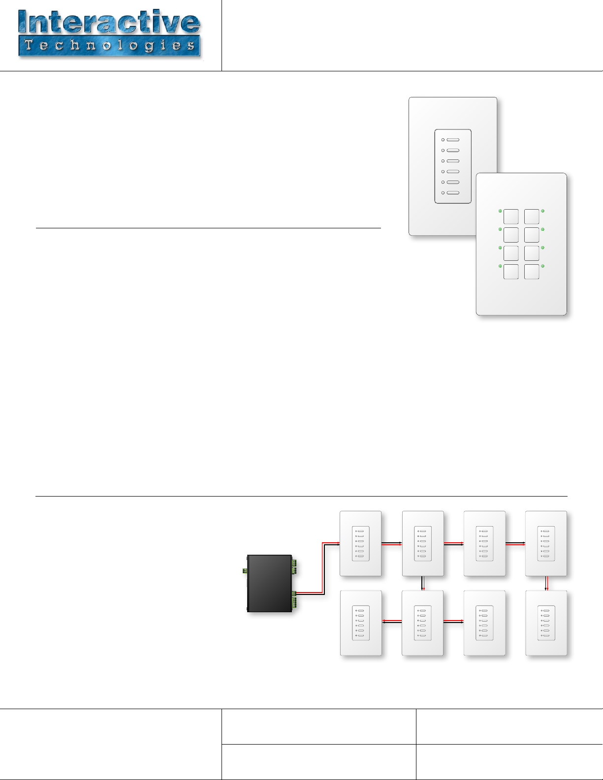
• The 2-Wire CueStation Bus uses a
2-conductor 16AWG or 18AWG cable
(see Features above for details) to
carry both power and data to and from
each station location. The network is
both topology free (meaning a random
combination of “star” and “daisy-chain”
connections may be used) and polarity
free (meaning it does not matter if the
conductors are reversed at any station).
NOTE: Use of inferior cable types may
seriously degrade performance, especially on
longer cable runs.
Interactive Technologies, Inc.
5295 Lake Pointe Circle Drive, Suite 100
Cumming, GA 30041 USA
678-455-9019 (Phone)
678-455-9071 (Fax)
ST-HUB
ST-UD6 ST-UD6 ST-UD6 ST-UD6
Catalog #: Project:
Prepared by: Date:
Page 2
Conguration
Setting LED Colors
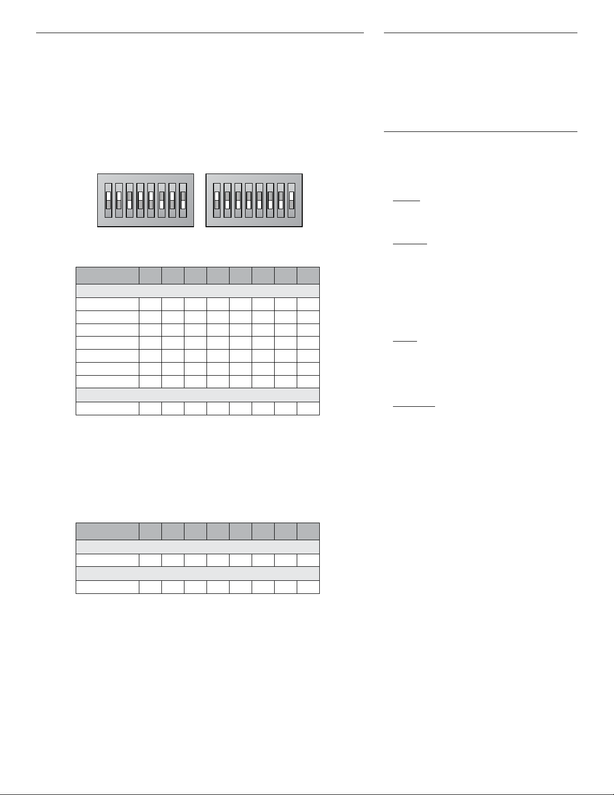
Every station connected to a Hub must be assigned a unique station
address from 1 through 64. Also, the number of physical buttons on the station
must be properly selected. These assignments are made by setting DIP Switches
on the back of the station.
View the DIP Switches so that the writing on the switches is upright, with the word
“ON” in the top left corner. There are two banks of 8 switches. The bank of 8
on the left side are the option switches. The bank of 8 on the right side are the
address switches.
ON
1 2 3 4 5 6 7 8
Option Switches Address Switches
Option Switches 1 2 3 4 5 6 7 8
Number of Buttons on Station
1-Button Station
2-Button Station OFF
3-Button Station
4-Button Station OFF OFF
5-Button Station
6-Button Station OFF
8-Button Station OFF OFF OFF
Reserved Switches Must Be As Specied
Reserved
ON ON
ON
1 2 3 4 5 6 7 8
OFF OFF
ON
OFF
ON
OFF
ON ON
OFF
ON
ON
ON ON
ON
OFF
OFF
ON
The color and intensity of each individual LED on
a 2-Wire station are controlled remotely.
See the CueStation Hub Hardware and Installation
Guide for more information.
Ordering
2-Wire Digital CueStation:
ST- (series) D (buttons) - (color) - (indicators)
(series)
M Mystique Series
U Ultra Series
(buttons)
1 1 Button (Mystique or Ultra)
2 2 Button (Mystique or Ultra)
3 3 Button (Mystique or Ultra)
4 4 Button (Mystique or Ultra)
5 5 Button (Ultra Only)
6 6 Button (Ultra Only)
8 8 Button (Mystique Only)
(color)
CW White
CB Black
CI Ivory
CA Light Almond
(indicators)
RGB RGB LEDs
NL No LEDs
The station address is set using a binary combination of seven dip switches. The
table below shows the value of each switch when set to the ON position. To set a
station to Station 1, switch 1 should be ON and switches 2-7 should be OFF. To
set a station to Station 37, switches 1, 3 & 6 should be ON and switches 2, 4, 5 & 7
should be OFF.
Address Switches 1 2 3 4 5 6 7 8
Station Address
Binary Station Address +1 +2 +4 +8 +16 +32 +64
Protocol
CueServer Protocol
ON
Part Number Examples:
ST-MD8-CW-RGB
Mystique 2-Wire 8-Button Station White
with RGB Indicators
ST-UD6-CB-RGB
Ultra 2-Wire 6-Button Station Black with
RGB Indicators
ST-UD2-CA-NL
Ultra 2-Wire 2-Button Station Light Almond
with No Indicators
© 2011-2014 Interactive Technologies, Inc. Interactive reserves the right to modify this document and/or the product(s) it describes without notice. In no event shall Interactive be
liable for incidental or consequential damages, or for the infringement of any patent rights or third party rights, due to the use of its products. D0640E 8/6/2014
 Loading...