

Page 1

ST-HUB and ST-HUB-EN
CueStation Network Hub Communications
Protocol and Hardware Reference Guide
Introduction
The ST-HUB CueStation Universal Network Hub is
used to both power and control an array of digital
CueStations (both 2-Wire and 4-Wire types) using either
an RS-232 protocol or an optional Ethernet protocol.
This document describes the communications protocol
CueStation
Universal Network Hub
Power Input
12-24V AC/DC
Copyright © Interactive Technologies, Inc. - www.interactive-online.com
™
Ethernet
Serial Port
for the Hub’s functions, which includes receiving button
press, hold and release events from the stations as
well as sending button indicator messages back to the
stations.
Station Bus Auxiliary Ports
4-Wire RS-232
S
V-V+ B A Rx BG GTx AXY
2-Wire RS-485
You should use this document to understand the
low-level protocol for communicating with the
button stations, which is useful for integrating digital
Ethernet
Bus Com
CueStations with 3rd Party systems or custom
applications.
If you are integrating CueStation button stations with our CueServer DMX processors, there is no need (other than idle curiosity) to read
this document, because CueServer automatically communicates with CueStations without the user needing to know the communications
protocol.
Hardware
In additional to the main power supply input for the CueStation Hub, there are two host interfaces, two button station interfaces and two
auxiliary ports available on the Hub. This section describes the use and conguration of each.
Power Supply
The CueStation Hub requires it’s own local power supply, from 12 to 24 volts, either AC or DC. The amount of current required can be
calculated by using one of the following equations (the current is dependent on the number of CueStations connected to the Hub):
• In Watts: 4 Watts + 0.6 Watts per 2-Wire Station + 1.5 Watts per 4-Wire Station
• In Milliamps (12VDC): 333mA + 50mA per 2-Wire Station + 125mA per 4-Wire Station
• In Milliamps (24VDC): 167mA + 25mA per 2-Wire Station + 63mA per 4-Wire Station
There are two power input jacks on the Hub, a 2.1mm DC Input Jack and a 2-Position Terminal Block. You can use either one, but not
both. If the 2.1mm DC Input Jack is used, it electrically disconnects the circuit from the Terminal Block input.
The standard power supply typically provided with the CueStation Hub outputs 1000mA at 12VDC, which is typically enough current to
handle up to ten 2-Wire stations or ve 4-Wire stations connected to the Hub.
Interactive Technologies, Inc.
5040 Magnolia Cree k Dri ve
Cumming, GA 3 0028 USA
678-455-9019 (Phon e)
678-455-9071 (Fax)
Professional Entertainment and Architectural Lighting Control Products
For additional product information and support:
www.interactive-online.com
Page 2
RS-232
The CueStation Hub communicates with Host devices via RS-232 serial data. The Hub has two connections for RS-232 signals, a
standard Female DB-9 serial port and a 3-Position Terminal Block for direct wiring. Either one of these ports may be used, but not
both at the same time (the two ports are internally connected directly together and cannot accept signals from two different devices
simultaneously).
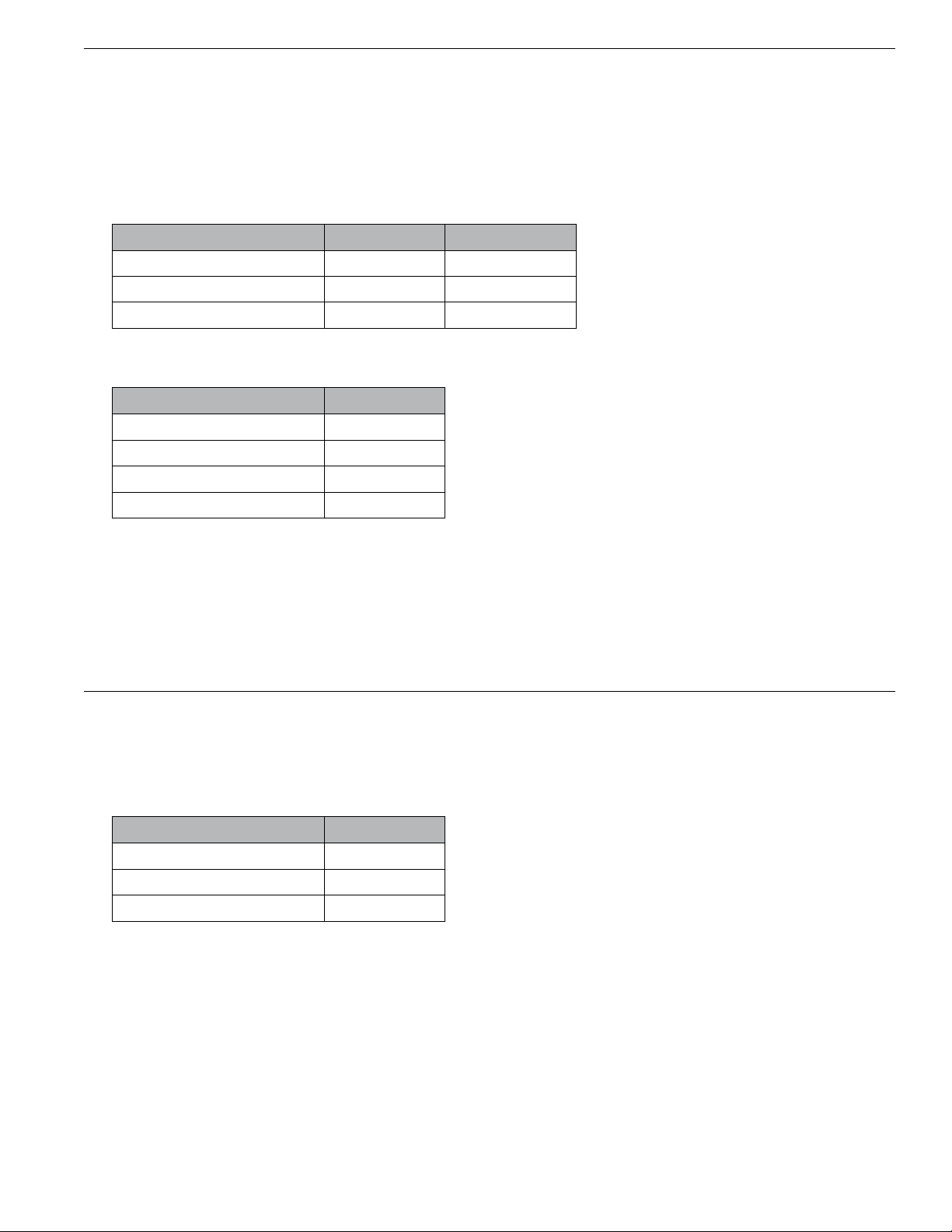
The following diagram shows the pinout of the Female DB-9 as well as the corresponding position of the RS-232 Terminal Block:
Signal DB-9 Pin RS-232 Port Pin
Serial Tx (to external device) 2 Tx
Serial Rx (from external device) 3 Rx
Ground 5 G
The serial port uses the following parameters for communication with the Host:
Serial Parameter Value
Baud Rate 38,400 bps
Data Bits 8
Parity None
Stop Bits 1
When the Hub senses a button event on a station, it will send a string via it’s serial port to the Host. When the Host wants to change
the state of a station’s indicator, the Host should send a string back to the Hub.
The strings sent and received on the serial port contain one or more CueStation messages, each of which look similar to “<BD0104>”.
This is an example of a message that means that Button 4 on Station 1 was pressed down. Complete details about CueStation
messages are given in the “Protocol” section of this document.
Ethernet
If the Hub is outtted with the optional Ethernet option (ST-HUB-EN), you can connect a standard CAT-5 type Ethernet cable to the
Ethernet jack for communications with the Host device.
The Hub uses Multicast UDP packets to communicate to and from the Host. The parameters for Ethernet communications are below:
Ethernet Parameter Value
Multicast Address 239.255.204.3
Port 52737
Protocol UDP
When the Hub senses a button event on a station, it will broadcast a packet to the Multicast group (which will be received by the Host).
When the Host wants to change the state of a station’s indicator, the Host should broadcast a packet to the Multicast group (which will
be received by the Hub).
The packets each contain one or more CueStation messages, each of which look similar to “<BD0104>”. This is an example of a
message that means that Button 4 on Station 1 was pressed down. Complete details about CueStation messages are given in the
“Protocol” section of this document.
Page 3

CueStation Bus
CueStations of both the 2-Wire and 4-Wire type can be connected to the Hub simultaneously. They are connected to the 2-Position
and 5-Position Terminal Blocks available on the rear of the unit (the center pin of the 5-Position Terminal Block is for a cable shield, if
present, which is not typically used).
Each station has a station address, which is set by a group of dip switches on the back of each station. Each station must have a
unique address. Please see the documentation for each station type to determine the appropriate dip switch settings.
4-Wire Station Bus Wiring
The 4-Wire CueStation Bus uses a 4-conductor 22/18 AWG Multi-Media Cable (Belden 1502 or similar). The network topology may
be run in “daisy-chain” style only and all four conductors must be wired through without reversing polarity of the data lines.
A maximum of fty (50) 4-Wire stations can be connected to a single CueStation Hub. The maximum distance from the Hub to the
farthest 4-Wire Station is 4000 feet (1220m).
4-Wire Station Bus Wiring Example
2-Wire Station Bus Wiring
The 2-Wire CueStation Bus uses a 2-conductor 18 AWG cable (Belden 9740 or similar) to carry both power and data to and from each
station location. The network is both topology free (meaning a random combination of “star” and “daisy-chain” connections may be
used) and polarity free (meaning it does not matter if the conductors are reversed at any station).
A maximum of ten (10) 2-Wire stations can be connected to a single CueStation Hub. The maximum distance from the Hub to the
farthest 2-Wire Station is 500 feet (150m).
2-Wire Station Bus Wiring Example
Page 4

RS-485 Port
The terminal block port marked “RS-485” is not used at this time. Do not connect anything to this port.
CueStation Messages
The messages passed between the CueStation Hub and the Host(s) are short ASCII-based strings. Each message begins with a lessthan symbol (“<”). The next two characters are a message code. Then each message has several parameters that follows. After the
parameters, the message ends with a greater-than symbol (“>”). The following illustration shows the basic structure of a CueStation
message:
“<” + 2-Character Message Code + Parameters + “>”
The same message strings are used for both RS-232 communication as well as via UDP packets. When more than one message is
needed, several messages can be strung together in a single packet or serial transmission.
The CueStation Hub ignores any characters received that are not enclosed in < angle-brackets >.
The following sections describe each message in detail.
Button Down Message
Message Format: <BD{station-number}{button-number}>
{station-number} = The station number, expressed in hexadecimal digits, from 01 to 32 (corresponding
to stations 1 through 50).
{button-number} = The number of the button on the station, from 01 to 08.
Description: The Button Down message is sent by the Hub to any connected Hosts whenever the Hub detects that a button
is pressed on a station.
Example: <BD0104>
The message above would be sent from the Hub whenever Button #4 was pressed down on Station #1.
Button Up Message
Message Format: <BU{station-number}{button-number}>
{station-number} = The station number, expressed in hexadecimal digits, from 01 to 32 (corresponding
to stations 1 through 50).
{button-number} = The number of the button on the station, from 01 to 08.
Description: The Button Up message is sent by the Hub to any connected Hosts whenever the Hub detects that a button
that had previously been pressed has now been released.
Example: <BU0307>
The message above would be sent from the Hub whenever Button #7 was released on Station #3.
Page 5

Button Maintained Message
Message Format: <BM{station-number}{button-number}>
{station-number} = The station number, expressed in hexadecimal digits, from 01 to 32 (corresponding
to stations 1 through 50).
{button-number} = The number of the button on the station, from 01 to 08.
Description: The Button Maintained message is sent by the Hub to any connected Hosts whenever the Hub detects that a
button continues to be held down by the user for an extended period of time. After a button has been pressed
and held down for one full second, a Button Maintained message is sent. The Button Maintained message
continues to be sent once-a-second until the user releases the button. The Button Down and Button Up
messages are always sent before and after a group of Button Maintained messages.
Example: <BM1C03>
The message above would be sent from the Hub whenever Button #3 was held down for more than one
second on Station #28 (1C in hexadecimal).
Indicator Set Message
Message Format: <IS{indicator-value}{station-number}{indicator-number}>
{indicator-value} = The value to set the indicator to, expressed in hexadecimal digits, from 00 to FF.
See the description below for details.
{station-number} = The station number, expressed in hexadecimal digits, from 01 to 32 (corresponding
to stations 1 through 50).
{indicator-number} = The number of the indicator on the station, from 01 to 08.
Description: The Indicator Set message is from a Host to the Hub to set the value of an LED indicator on a station. The
indicator’s value determines it’s color, intensity and ashing pattern. Depending on model, some stations do
not have the ability to remotely set the color of the LED indicator, in this case the color portion of the value is
ignored. See the section below that describes LED Indicator Values for specics on how to choose an indicator
value.
Example: <ISFF0A02>
The message above would be sent from a Host to a Hub to set the value of LED indicator #2 on station #10 (0A
in hexadecimal) to 255 (FF in hexadecimal).
Page 6

Indicator Values
Each indicator on a station can be set to one of 8 different colors, with 4 intensity levels and 8 ashing patterns. These parameters are
combined to provide 256 possible combinations, which can be expressed as a single 8-bit number.
The three parameters can be combined in a binary fashion to produce a value from 0 to 255 as expressed by the following chart. Add the
values (in parenthesis) of each parameter together to calculate the desired indicator value. For example, the value 0 is “Off”, the value 255
is “Full White”, the value 139 is Fast Flashing Red at 75% brightness.
Bit Position Bit Value Function Parameter
7 128
6 64
5 32
4 16
3 8
2 4
1 2
0 1
LED Intensity
LED Color
LED Flash Pattern
00( 0) = Intensity 25%
01( 64) = Intensity 50%
10(128) = Intensity 75%
11(192) = Intensity 100%
000( 0) = Black
001( 8) = Red
010( 16) = Green
011( 24) = Blue
100( 32) = Yellow
101( 40) = Magenta
110( 48) = Cyan
111( 56) = White
000( 0) = Off
001( 1) = Slow Flash
010( 2) = Rev. Slow Flash
011( 3) = Fast Flash
100( 4) = Rev. Fast Flash
101( 5) = Wink
110( 6) = Rev. Wink
111( 7) = On
Alternatively, you can use the complete table on the next page that shows all possible combinations of LED indicator values.
Page 7

Dec Hex Intensity Color Flash
0 00 25% Black Off
1 01 25% Black Slow
2 02 25% Black Rev. Slow
3 03 25% Black Fast
4 04 25% Black Rev. Fast
5 05 25% Black Wink
6 06 25% Black Rev. Wink
7 07 25% Black On
8 08 25% Red Off
9 09 25% Red Slow
10 0A 25% Red Rev. Slow
11 0B 25% Red Fast
12 0C 25% Red Rev. Fast
13 0D 25% Red Wink
14 0E 25% Red Rev. Wink
15 0F 25% Red On
16 10 25% Green Off
17 11 25% Green Slow
18 12 25% Green Rev. Slow
19 13 25% Green Fast
20 14 25% Green Rev. Fast
21 15 25% Green Wink
22 16 25% Green Rev. Wink
23 17 25% Green On
24 18 25% Blue Off
25 19 25% Blue Slow
26 1A 25% Blue Rev. Slow
27 1B 25% Blue Fast
28 1C 25% Blue Rev. Fast
29 1D 25% Blue Wink
30 1E 25% Blue Rev. Wink
31 1F 25% Blue On
32 20 25% Yellow Off
33 21 25% Yellow Slow
34 22 25% Yellow Rev. Slow
35 23 25% Yellow Fast
36 24 25% Yellow Rev. Fast
37 25 25% Yellow Wink
38 26 25% Yellow Rev. Wink
39 27 25% Yellow On
40 28 25% Magenta Off
41 29 25% Magenta Slow
42 2A 25% Magenta Rev. Slow
43 2B 25% Magenta Fast
44 2C 25% Magenta Rev. Fast
45 2D 25% Magenta Wink
46 2E 25% Magenta Rev. Wink
47 2F 25% Magenta On
48 30 25% Cyan Off
49 31 25% Cyan Slow
50 32 25% Cyan Rev. Slow
51 33 25% Cyan Fast
52 34 25% Cyan Rev. Fast
53 35 25% Cyan Wink
54 36 25% Cyan Rev. Wink
55 37 25% Cyan On
56 38 25% White Off
57 39 25% White Slow
58 3A 25% White Rev. Slow
59 3B 25% White Fast
60 3C 25% White Rev. Fast
61 3D 25% White W ink
62 3E 25% White Rev. Wink
63 3F 25% White On
Dec Hex Intensity Color Flash
64 40 50% Black Off
65 41 50% Black Slow
66 42 50% Black Rev. Slow
67 43 50% Black Fast
68 44 50% Black Rev. Fast
69 45 50% Black W ink
70 46 50% Black Rev. Wink
71 47 50% Black On
72 48 50% Red Off
73 49 50% Red Slow
74 4A 50% Red Rev. Slow
75 4B 50% Red Fast
76 4C 50% Red Rev. Fast
77 4D 50% Red Wink
78 4E 50% Red Rev. Wink
79 4F 50% Red On
80 50 50% Green Off
81 51 50% Green Slow
82 52 50% Green Rev. Slow
83 53 50% Green Fast
84 54 50% Green Rev. Fast
85 55 50% Green Wink
86 56 50% Green Rev. Wink
87 57 50% Green On
88 58 50% Blue Off
89 59 50% Blue Slow
90 5A 50% Blue Rev. Slow
91 5B 50% Blue Fast
92 5C 50% Blue Rev. Fast
93 5D 50% Blue Wink
94 5E 50% Blue Rev. Wink
95 5F 50% Blue On
96 60 50% Yellow Off
97 61 50% Yellow Slow
98 62 50% Yellow Rev. Slow
99 63 50% Yellow Fast
100 64 50% Yellow Rev. Fast
101 65 50% Yellow Wink
102 66 50% Yellow Rev. W ink
103 67 50% Yellow On
104 68 50% Magenta Off
105 69 50% Magenta Slow
106 6A 50% Magenta Rev. Slow
107 6B 50% Magenta Fast
108 6C 50% Magenta Rev. Fast
109 6D 50% Magenta Wink
110 6E 50% Magenta Rev. Wink
111 6F 50% Magenta On
112 70 50% Cyan Off
113 71 50% Cyan Slow
114 72 50% Cyan Rev. Slow
115 73 50% Cyan Fast
116 74 50% Cyan Rev. Fast
117 75 50% Cyan Wink
118 76 50% Cyan Rev. Wink
119 77 50% Cyan On
120 78 50% White Off
121 79 50% White Slow
122 7A 50% White Rev. Slow
123 7B 50% White Fast
124 7C 50% White Rev. Fast
125 7D 50% White Wink
126 7E 50% White Rev. Wink
127 7F 50% White On
Page 8
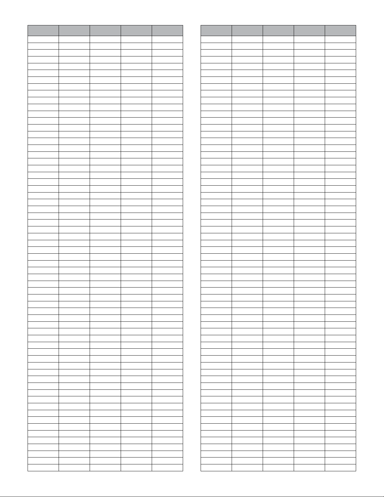
Dec Hex Intensity Color Flash
128 80 75% Black Off
129 81 75% Black Slow
130 82 75% Black Rev. Slow
131 83 75% Black Fast
132 84 75% Black Rev. Fast
133 85 75% Black Wink
134 86 75% Black Rev. Wink
135 87 75% Black On
136 88 75% Red Off
137 89 75% Red Slow
138 8A 75% Red Rev. Slow
139 8B 75% Red Fast
140 8C 75% Red Rev. Fast
141 8D 75% Red Wink
142 8E 75% Red Rev. Wink
143 8F 75% Red On
144 90 75% Green Off
145 91 75% Green Slow
146 92 75% Green Rev. Slow
147 93 75% Green Fast
148 94 75% Green Rev. Fast
149 95 75% Green Wink
150 96 75% Green Rev. Wink
151 97 75% Green On
152 98 75% Blue Off
153 99 75% Blue Slow
154 9A 75% Blue Rev. Slow
155 9B 75% Blue Fast
156 9C 75% Blue Rev. Fast
157 9D 75% Blue Wink
158 9E 75% Blue Rev. Wink
159 9F 75% Blue On
160 A0 75% Yellow Off
161 A1 75% Yellow Slow
162 A2 75% Yellow Rev. Slow
163 A3 75% Yellow Fast
164 A4 75% Yellow Rev. Fast
165 A5 75% Yellow Wink
166 A6 75% Yellow Rev. W ink
167 A7 75% Yellow On
168 A8 75% Magenta Off
169 A9 75% Magenta Slow
170 AA 75% Magenta Rev. Slow
171 AB 75% Magenta Fast
172 AC 75% Magenta Rev. Fast
173 AD 75% Magenta W ink
174 AE 75% Magenta Rev. Wink
175 AF 75% Magenta On
176 B0 75% Cyan Off
171 B1 75% Cyan Slow
178 B2 75% Cyan Rev. Slow
179 B3 75% Cyan Fast
180 B4 75% Cyan Rev. Fast
181 B5 75% Cyan Wink
182 B6 75% Cyan Rev. Wink
183 B7 75% Cyan On
184 B8 75% White Off
185 B9 75% White Slow
186 BA 75% White Rev. Slow
187 BB 75% White Fast
188 BC 75% White Rev. Fast
189 BD 75% White Wink
190 BE 75% White Rev. Wink
191 BF 75% White On
Dec Hex Intensity Color Flash
192 C0 100% Black Off
193 C1 100% Black Slow
194 C2 100% Black Rev. Slow
195 C3 100% Black Fast
196 C4 100% Black Rev. Fast
197 C5 100% Black W ink
198 C6 100% Black Rev. Wink
199 C7 100% Black On
200 C8 100% Red Off
201 C9 100% Red Slow
202 CA 100% Red Rev. Slow
203 CB 100% Red Fast
204 CC 100% Red Rev. Fast
205 CD 100% Red Wink
206 CE 100% Red Rev. Wink
207 CF 100% Red On
208 D0 100% Green Off
209 D1 100% Green Slow
210 D2 100% Green Rev. Slow
211 D3 100% Green Fast
212 D4 100% Green Rev. Fast
213 D5 100% Green Wink
214 D6 100% Green Rev. Wink
215 D7 100% Green On
216 D8 100% Blue Off
217 D9 100% Blue Slow
218 DA 100% Blue Rev. Slow
219 DB 100% Blue Fast
220 DC 100% Blue Rev. Fast
221 DD 100% Blue Wink
222 DE 100% Blue Rev. Wink
223 DF 100% Blue On
224 E0 100% Yellow Off
225 E1 100% Yellow Slow
226 E2 100% Yellow Rev. Slow
227 E3 100% Yellow Fast
228 E4 100% Yellow Rev. Fast
229 E5 100% Yellow Wink
230 E6 100% Yellow Rev. Wink
231 E7 100% Yellow On
232 E8 100% Magenta Off
233 E9 100% Magenta Slow
234 EA 100% Magenta Rev. Slow
235 EB 100% Magenta Fast
236 EC 100% Magenta Rev. Fast
237 ED 100% Magenta Wink
238 EE 100% Magenta Rev. Wink
239 EF 100% Magenta On
240 F0 100% Cyan Off
241 F1 100% Cyan Slow
242 F2 100% Cyan Rev. Slow
243 F3 100% Cyan Fast
244 F4 100% Cyan Rev. Fast
245 F5 100% Cyan W ink
246 F6 100% Cyan Rev. Wink
247 F7 100% Cyan On
248 F8 100% White Off
249 F9 100% White Slow
250 FA 100% White Rev. Slow
251 FB 100% White Fast
252 FC 100% White Rev. Fast
253 FD 100% White Wink
254 FE 100% White Rev. Wink
255 FF 100% White On
D0609A
 Loading...