


Scape®
Movable
smo55-005
Operating Manual

1. General
—
Scape® Movable
Operating Manual
Contents
1. General _____________________________________________________________________________________________________________ 5
1.1. Safety instructions ____________________________________________________________________________________________________ 5
1.2. Scope of delivery _____________________________________________________________________________________________________ 7
1.3. Cleaning instructions ________________________________________________________________________________________________ 8
1.4. Transportation instructions __________________________________________________________________________________________ 8
2. Specifications and set up ___________________________________________________________________________________________ 9
2.1. Specifications ________________________________________________________________________________________________________ 9
2.2. Connections and controls __________________________________________________________________________________________ 10
2.2.1. Lift frame ________________________________________________________________________________________________________ 10
2.2.2. Integrated PC ____________________________________________________________________________________________________ 12
2.2.3. Touch screen ____________________________________________________________________________________________________ 13
2.2.4. Remote control___________________________________________________________________________________________________ 14
3. Installation ________________________________________________________________________________________________________ 15
3.1. Notes ________________________________________________________________________________________________________________ 15
3.2. Connection to the power supply _____________________________________________________________________________________ 15
3.3. Connection to the network __________________________________________________________________________________________ 15
4. Switching on ______________________________________________________________________________________________________ 16
5. Display settings – OSD ____________________________________________________________________________________________ 17
5.1. OSD usage ___________________________________________________________________________________________________________ 17
5.2. Select input source __________________________________________________________________________________________________ 17
6. Integrated PC _____________________________________________________________________________________________________ 18
7. Troubleshooting tips ______________________________________________________________________________________________ 19
7.1. Manufacturer – Support _____________________________________________________________________________________________ 19
7.2. Problems and solutions ______________________________________________________________________________________________ 19
Scape® Movable Technical specifications are subject
smo55-005 to change witho ut notice.
Operating Manua l Version 1.6 – Status: 12/2019
Page 2 of 33 poc: SFi

1. General
—
8. Appendix _________________________________________________________________________________________________________ 20
8.1. Technical data ______________________________________________________________________________________________________ 20
8.1.1. Scape® Movable _________________________________________________________________________________________________ 20
8.1.2. Touch screen ____________________________________________________________________________________________________ 20
8.1.3. Silent PC _________________________________________________________________________________________________________ 21
8.2. Technical Drawings_________________________________________________________________________________________________ 22
8.2.1. Perspective ______________________________________________________________________________________________________ 22
8.2.2. Horizontal – Top view ___________________________________________________________________________________________ 23
8.2.3. Horizontal – Front view (high) __________________________________________________________________________________ 24
8.2.4. Horizontal – Front view (low) ___________________________________________________________________________________ 25
8.2.5. Horizontal – Right view (high) __________________________________________________________________________________ 26
8.2.6. Horizontal – Right view (low) ___________________________________________________________________________________ 27
8.2.7. Vertical – Top view ______________________________________________________________________________________________ 28
8.2.8. Vertical – Front view (high) _____________________________________________________________________________________ 29
8.2.9. Vertical – Front view (low) _____________________________________________________________________________________ 30
8.2.10. Vertical – Right view (high) _____________________________________________________________________________________ 31
8.2.11. Vertical – Right view (low) _____________________________________________________________________________________ 32
Scape® Movable Technical specifications are subject
smo55-005 to change witho ut notice.
Operating Manua l Version 1.6 – Status: 12/2019
Page 3 of 33 poc: SFi

1. General
—
Notes
This is a class A device according to EN55022.
For more information, please refer to Chapter 1.1 - Radio interference.
This device complies with Part 15 of the FCC Rules. Operation is subject to the
following two conditions: (1) this device may not cause harmful interference,
and (2) this device must accept any interference received, including interference
that may cause undesired operation.
This Class A digital apparatus complies with Canadian ICES-003.
This manual is applicable for the following devices:
· Scape® Movable 55" (smo55-005 with st55-005 and pcsi-005)
Information in this document is subject to change without notice.
©2019 Interactive Scape GmbH. All rights reserved.
The document or excerpts from the document may not be duplicated without the prior permission of Interactive Scape
GmbH.
Interactive Scape GmbH shall not be liable for any errors contained in this document or any other incidental or
consequential damages resulting from the delivery, use or application of this material.
All product names mentioned in this document are trademarks or registered trademarks of their respective owners.
Scape® Movable Technical specifications are subject
smo55-005 to change witho ut notice.
Operating Manua l Version 1.6 – Status: 12/2019
Page 4 of 33 poc: SFi

1. General
—
1. General
This manual describes the safe installation, configuration and correct operation of the Scape® Movable.
If your device does not have an integrated PC, you can skip the chapters and notes about the integrated PC. All other
notes and instructions continue to apply without restriction.
If necessary, pay attention to the supplementary documents, such as the installation instructions.
1.1. Safety instructions
Before using and operating your Scape® Movable, observe the following safety instructions to prevent you, your
environment or the Scape® Movable from being damaged.
Fire and electric shock
Overloaded sockets, extension cords and power strips can cause fire and electric shock.
· Avoid using power strips and extension cords if possible.
· Do not chain multiple extension cords or power strips together.
Overheating
Heat build-up can overheat the screen and the integrated PC. This can damage the device.
· Ensure there is sufficient air circulation around the Scape® Movable.
· Make sure all the ventilation holes on around the screen and integrated PC are uncovered.
Excess voltage from lightning strikes
In the event of a thunderstorm there is a risk of excess voltage damage from lightning strikes electrical appliances that
are plugged in.
· Do not install the Scape® Movable during a thunderstorm.
· Disconnect the devices from the mains during thunderstorms.
Moisture, liquid and steam
Moisture, liquid and steam inside the Scape® Movable can cause electric shocks or short circuits.
· Only use the Scape® Movable indoors.
· Do not allow liquids to get inside the Scape® Movable.
· Protect your Scape® Movable from steam and moisture.
Scape® Movable Technical specifications are subject
smo55-005 to change witho ut notice.
Operating Manua l Version 1.6 – Status: 12/2019
Page 5 of 33 poc: SFi

1. General
—
Improper cleaning
Improper cleaning with harsh detergents and solvents or soaking wet cloths can damage the Scape® Movable.
· Observe the information on cleaning your Scape® Movable (see Chapter 1.3 - Cleaning instructions).
Improper opening and repair
Improper opening and improper repairs may be dangerous to users of the device.
· Do not open the housing of the device.
· In case of repair contact the manufacturer or a specialist dealer.
Radio interference
Radio interference can be generated by any device that emits electromagnetic signals. Due to the large number of
devices that transmit and receive radio waves, interference from overlapping radio waves can occur.
· Do not use the Scape® Movable in locations where the use of radio equipment is prohibited.
· Always follow the instructions and instructions of authorized persons to switch off radio equipment, especially in
hospitals, outpatient health centers, medical practices and other medical facilities, to avoid interference with sensitive
medical equipment.
· Check with your doctor or the manufacturer of your medical device (pacemaker, hearing aid, implant with electronic
control, etc.) to see if it can work your Scape® Movable without interference.
· If necessary, maintain the minimum distance of 15 cm recommended by medical device manufacturers to avoid
interference with your medical device.
Hazardous environments
Under unfavorable conditions, radio waves near explosive atmospheres may lead to fire or explosions.
· Do not install and operate the Scape® Movable near explosive gases, flammable gases, areas where the air contains
chemicals or particles such as grain, dust or metal powders, and near detonation zones.
· In places with potentially explosive gases and near detonation zones, follow the instructions for switching off the
electronic devices to avoid disruption of the blasting and ignition systems.
Load and damage to the surface
Rough, hard or sharp-edged materials and heavy objects can damage the screen surface of the Scape® Movable.
· Do not place heavy objects on the screen.
· Use only objects with smooth or soft bottom surfaces on the screen.
· Clean the undersides of the objects before and after each use.
Scape® Movable Technical specifications are subject
smo55-005 to change witho ut notice.
Operating Manua l Version 1.6 – Status: 12/2019
Page 6 of 33 poc: SFi

1. General
—
Notes on the lift frame
Improper or careless operation of the screen with the lift frame can result in damage to your Scape® Movable or its
surroundings or to serious injury.
· The lift function of the Scape® Movable may only be operated by adults.
· Make sure that there are no equipment, other objects or people within the range of movement.
· Never reach into the rack during movement. There is an acute risk of injury.
· During movement, be aware of unusual noises or irregular movement of the device. Stop immediately if you observe
anything unusual.
· If the control element of the lift frame makes an unusual smell or noise, stop operation immediately and disconnect the
unit from the mains.
· Always leave the brakes on the lift frame castors engaged and only release them when the Scape® Movable has to be
moved.
· After moving, reengage the brakes on the lift frame castors.
· Move the lift frame only when it is fully retracted (lowest position) and rotated vertically.
· Before moving the device, disconnect it from the mains supply – pull out the mains plug.
1.2. Scope of delivery
The following accessories are included with your Scape® Movable:
· IEC power connector to connect to the mains
· Wireless keyboard with trackpad
· Infrared remote control (receiver on the back panel)
· Screen cleaning kit
· Operating manual (possibly by email)
Scape® Movable Technical specifications are subject
smo55-005 to change witho ut notice.
Operating Manua l Version 1.6 – Status: 12/2019
Page 7 of 33 poc: SFi

1. General
—
1.3. Cleaning instructions
The touch sensor of the Scape® Movable does not usually need to be serviced. Nevertheless, it is recommended to
clean the glass surface of the screen regularly.
· Disconnect the device from the mains before cleaning.
· Typically, a solution of isopropyl alcohol and water (50:50 blend ratio) or the included screen cleaning kit are best for
cleaning the touch sensor.
· Apply the solution to a soft, lint-free cloth. Avoid using rough cloths.
· Use the cloth to clean the glass surface. Apply the liquid only to the cloth and never directly to the device. This will
prevent liquid from entering the inside of the device or causing marks on the frame.
1.4. Transportation instructions
The safest way to transport your device is in a Scape® Movable flight case (sold separately).
· Set the display to the fully vertical position for transport and move it to the lowest position.
· Apply the brakes on the castors of the lift frame during transportation.
· Secure the device or flightcase against slipping and tipping.
Scape® Movable Technical specifications are subject
smo55-005 to change witho ut notice.
Operating Manua l Version 1.6 – Status: 12/2019
Page 8 of 33 poc: SFi

2. Specifications and set up
Prestop lift frame
vertically / horizontally movable
Maximum load 100 kg
Zotac Silent PC
2
NVIDIA GeForce RTX 2060 6GB
16 GB RAM
256 GB SSD
Operating system
Windows 10 Professional
Display
3840 x 2160 (UHD) 60 Hz
1.07 billion colors
6 ms response time
Connections
2x HDMI
1x DisplayPort
Touch
3M
(optional) integrated Capore® Touch & Object Recognition
—
2. Specifications and set up
2.1. Specifications
Lift frame
Integrated PC
.4 – 4.1 GHz Intel Core i5 9300H
Touch screen
sensor
2.0
– PCAP (80 touches)
Scape® Movable Technical specifications are subject
smo55-005 to change witho ut notice.
Operating Manua l Version 1.6 – Status: 12/2019
Page 9 of 33 poc: SFi

2. Specifications and set up
1
IEC p
1
—
2.2. Connections and controls
2.2.1. Lift power connection
ower connection (230V / 50Hz) - fused
Scape® Movable Technical specifications are subject
smo55-005 to change witho ut notice.
Operating Manua l Version 1.6 – Status: 12/2019
Page 10 of 33 poc: SFi

2. Specifications and set up
element.
2
Raise height (mode 1) &
3
Lower height (mode 1) & - move to the horizontal (mode 2)
4
Switch modes
5
Preset 1
6 Preset 2
7
Set presets
8 Display
2
3 4 5 6 7
8
—
2.2.2. Lift remote
- move to the vertical (mode 2)
On the Scape® Movable you can set the height of the screen as well as its inclination. Press the Mode button (4) to
switch between the Height Adjustment (Mode 1) and Tilt Adjustment (Mode 2) modes. The display (8) will show you the
respective number after changing the mode. Now set the desired height or tilt of the screen using the position moving
buttons (2 & 3).
You have the possibility to save 2 positions and recall them later. Adjust height and inclination as desired. Press the
memory button (7) for 3 seconds and then select the desired memory location I (5) or II (6).
To return to the stored position later, press and hold the button for the corresponding memory location until the screen
is in the stored position.
Make sure that there is enough space around the device and that
the device does not touch anything during the procedure.
Do not touch the lift frame during the procedure!
During the procedure, touch the device only at the control
Scape® Movable Technical specifications are subject
smo55-005 to change witho ut notice.
Operating Manua l Version 1.6 – Status: 12/2019
Page 11 of 33 poc: SFi

2. Specifications and set up
1
Switch
2
SD(HC/XC)-Slot
3 USB
4
Microphone input (3.5mm jack)
5 Audio output (3.5mm jack)
6
USB 3.1 (type C)
7 Power supply
8
Gigabit Ethernet (internal – Capore®)
9 Gigabit Ethernet (external)
10
2x external WIFI antennas
11 DisplayPort out
12
HDMI 2.0 out
13
USB 3.1 (type C)
14
USB 3.0 (type A)
1 2 3 4 5
6 7 8 9 10
11
12
13
14
—
2.2.3. Integrated PC
PC on / off
3.1 (type A)
Scape® Movable Technical specifications are subject
smo55-005 to change witho ut notice.
Operating Manua l Version 1.6 – Status: 12/2019
Page 12 of 33 poc: S Fi

2. Specifications and set up
1 IR
2
Switch between Touch TUIO / USB Touch
3 RJ
4
USB-Connection Type B – for direct connection of touch and PC
5 Line Out Output
6
DisplayPort 1.2 input
7 2x HDMI 2.0 input
8
HDMI 1.4 input
9
Stand-by
10
Status LED
11
Close OSD / > back / > show input selection
12
Plus / Right
13
Minus / Left
14 Open OSD / confirm selection
15
IEC socket for connection to 230V 50Hz
16
Main power switch
1 2 3 4 5
6 7 8
9
10
11
12
13
14
15
16
—
2.2.4. Touch screen
The screen of the Scape® Movable comes preinstalled and connected to the integrated PC ready for operation.
-Sensor for remote control
-45 Lan interface – to use the Capore® Touch & Object Assistant
*(17)
*(23)
*(22)
*analogue to button on remote control
(UHD 60 Hz)
*(21)
*(20)
Scape® Movable Technical specifications are subject
smo55-005 to change witho ut notice.
Operating Manua l Version 1.6 – Status: 12/2019
Page 13 of 33 poc: SFi
2. Specifications and set up
17 Stand
18
Display mode selection
19 Show input
20
Show OSD / confirm selection
21 Close OSD
22
Left / Minus
23 Right / Plus
—
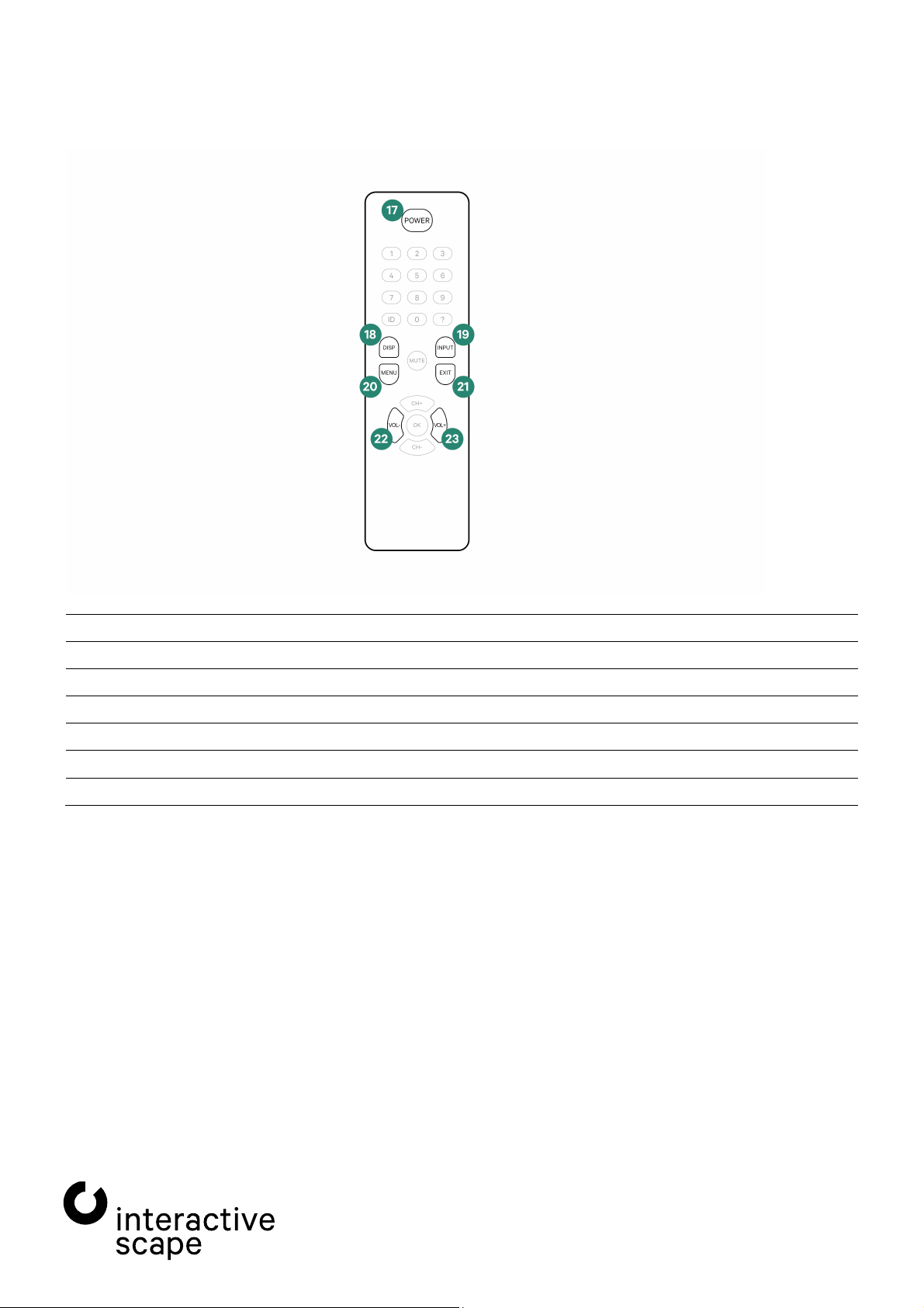
2.2.5. Remote control
-by *(9)
-selection
*(14)
*(11)
*(13)
*(12)
*
analogous to buttons on the screen
All keys on the remote control which are not explained above are not required for operation of Scape® Movable and do
not have any function.
The infrared remote control is located behind the Silent PC.
Scape® Movable Technical specifications are subject
smo55-005 to change witho ut notice.
Operating Manua l Version 1.6 – Status: 12/2019
Page 14 of 33 poc: SFi

3. Installation
—
3. Installation
The Scape® Movable is delivered ready for operation. All units are fully assembled and wired.
Place the device in a suitable location and connect it to the power supply.
3.1. Notes
Observe the following points when setting up the device:
· Give the Scape® Movable sufficient time to adapt to the ambient temperature. Otherwise the device may be damaged
or destroyed by condensation inside the device.
· Only operate the Scape® Movable indoors.
· Do not expose the Scape® Movable to direct sunlight.
· Make sure that there is enough space around the Scape® Movable to move the lift frame.
· Before operating your Scape® Movable, remove the white or red plastic protection on the rollers of the lift frame. To
do this, pull the white tab in the middle of each roller firmly. Note that the lift frame has 8 castors.
3.2. Connection to the power supply
Connect the Scape® Movable to the mains using the supplied IEC power cord via the power connection socket at the
base of the device (see Chapter 2.2.1 – Lift frame – item 1).
To do this, first plug the IEC plug into the corresponding socket on the device and then the earthed plug into the mains
socket.
When disconnecting the appliance from the mains, always pull the plug and do not pull the cable.
Do not touch the plug with wet hands.
3.3. Connection to the network
The Scape® Movable works completely without an internet or other network connection. However, both WLAN and the
Gigabit Ethernet port on the integrated PC (see Chapter 2.2.3 – Integrated PC – item 9) can be connected to the
internet or another network.
To use Capore® object recognition or touch via TUIO, set the switch for the touch signal on the back of the display to
"TUIO" (see Chapter 2.2.4 – Touch screen – item 2). For further information on setting up Capore® Touch & Object
recognition, refer to the operating manual for the "Capore® Touch & Object Assistant".
The default IP address of the integrated Capore® API Box is 10.0.0.20, subnet 255.255.255.0. You can access the web
interface of the Capore® API Box via that IP address. The Ethernet port of the Scape® Movable (see Chapter 2.2.3 –
Integrated PC – item 9) is set to obtain its IP address from a DHCP server.
Scape® Movable Technical specifications are subject
smo55-005 to change witho ut notice.
Operating Manua l Version 1.6 – Status: 12/2019
Page 15 of 33 poc: SFi

4. Switching on
Make sure that there are no objects on the display when the
there will be errors in the touch and object detection.
—
4. Switching on
Switch on the display using the main switch (see Chapter 2.2.4 – Touch screen – item 16). Then start the PC (see
Chapter 2.2.3 – Integrated PC – item 1).
device is switched on.
Do not touch the touch screen during device startup, otherwise
The device will take about 1.5 hours to power up before it reaches its final operating temperature. During this time, the
touch sensor of the device constantly adapts to its environment. This has a direct effect on long-term object
recognition.
If your application requires the Capore® objects to remain on the
screen for a long time, do not use object detection until the
device has reached its operating temperature.
Scape® Movable Technical specifications are subject
smo55-005 to change witho ut notice.
Operating Manua l Version 1.6 – Status: 12/2019
Page 16 of 33 poc: SFi

5. Display setti ngs – OSD
—
5. Display settings – OSD
5.1. OSD usage
The Scape® Movable OSD offers a variety of on-screen settings, such as signal input, display mode, and color and
brightness settings. The factory settings are suitable for most applications.
Press the Menu (20) button to display the OSD (see Chapter 2.2.5 – Connections and controls – Remote control).
Use the Plus (23) and Minus (22) buttons to navigate through the individual menu items.
The Menu (20) button takes you to the next level of the selected menu item or setting.
Use the Plus (23) and Minus (22) buttons to adjust the values for each setting or to select the appropriate option.
The Menu (20) button activates the selected option and returns to the last selection level.
The Exit (21) button resets the setting to its original value and returns to the next higher menu level or closes the OSD
when you are at the top menu level.
The OSD automatically shuts off after a few seconds of inactivity.
Abb. 1: Menu opened – select menu item Menu item selected - confirm Menu item opened – set value
5.2. Select input source
If no active device is connected to the selected input of the screen, you can use the OSD only to a limited extent. Press
Input (19) or Exit (21) on the IR remote control to open the input selection. Use the Plus (23) and Minus (22) buttons to
select the appropriate input and confirm the selection with the Menu (20) button.
Abb. 2: Input selection
The signal source is set to "Auto" by default and automatically detects the input.
Scape® Movable Technical specifications are subject
smo55-005 to change witho ut notice.
Operating Manua l Version 1.6 – Status: 12/2019
Page 17 of 33 poc: SFi

6. Integrated PC
—
6. Integrated PC
Unless you have specified otherwise, the integrated PC with Windows 10 Professional is pre-installed, fully configured
and ready to use.
Be sure to create a backup before changing the configuration of
the operating system and its components.
To do this, use the Windows backup tools (backup settings).
Your Scape® Movable with integrated PC comes with a wireless keyboard with integrated trackpad.
Follow the enclosed instructions to use the keyboard.
To switch on the integrated PC, press the power button on the front of the PC
(see Chapter 2.2.3 – Integrated PC – item 1).
A system user with administrator rights and the following access data has already been set up.
User name: ias
Password: ias
For the security of your system, it is strongly recommended that you change the password of this account.
Scape® Movable Technical specifications are subject
smo55-005 to change witho ut notice.
Operating Manua l Version 1.6 – Status: 12/2019
Page 18 of 33 poc: SFi

7. Troubleshooting tips
Error
Possible cause
Possible solution
No picture is shown even though
the PC is turned on.
The DisplayPort or HDMI cable has
come loose.
Check the connection of the cable with
the PC.
Plug the cable into another connector on
the PC
The screen is switched to the wrong
input.
Set the input correctly (see
Chapter 5.2 – Select input source).
The PC does not start up.
The PC is not receiving power.
On the back of the PC, check whether
the PC is connected to the power supply.
The PC or the screen turns off
unexpectedly.
Loose contact in the power supply
Check whether the
to the power supply and whether the IEC
plug is correctly inserted.
—
7. Troubleshooting tips
Do not open the housing of the Scape® Movable by yourself.
If your Scape® Movable does not work as intended, see Chapter 7.2 – Problems and Solutions) to find out if
there is a solution to your problem.
If you cannot find a solution, contact Interactive Scape Hardware Support. You can reach them on weekdays
at +49 30 698 094 150.
7.1. Manufacturer – Support
Interactive Scape GmbH
Wilhelmine-Gemberg-Weg 6
10179 Berlin
+49 (0)30 698 094 150
7.2. Problems and solutions
.
.
device is connected
Scape® Movable Technical specifications are subject
smo55-005 to change witho ut notice.
Operating Manua l Version 1.6 – Status: 12/2019
Page 19 of 33 poc: SFi

8. Appendix
Dimensions when the screen is
horizontal (Lx
1274 x 786 x 917/1564* mm
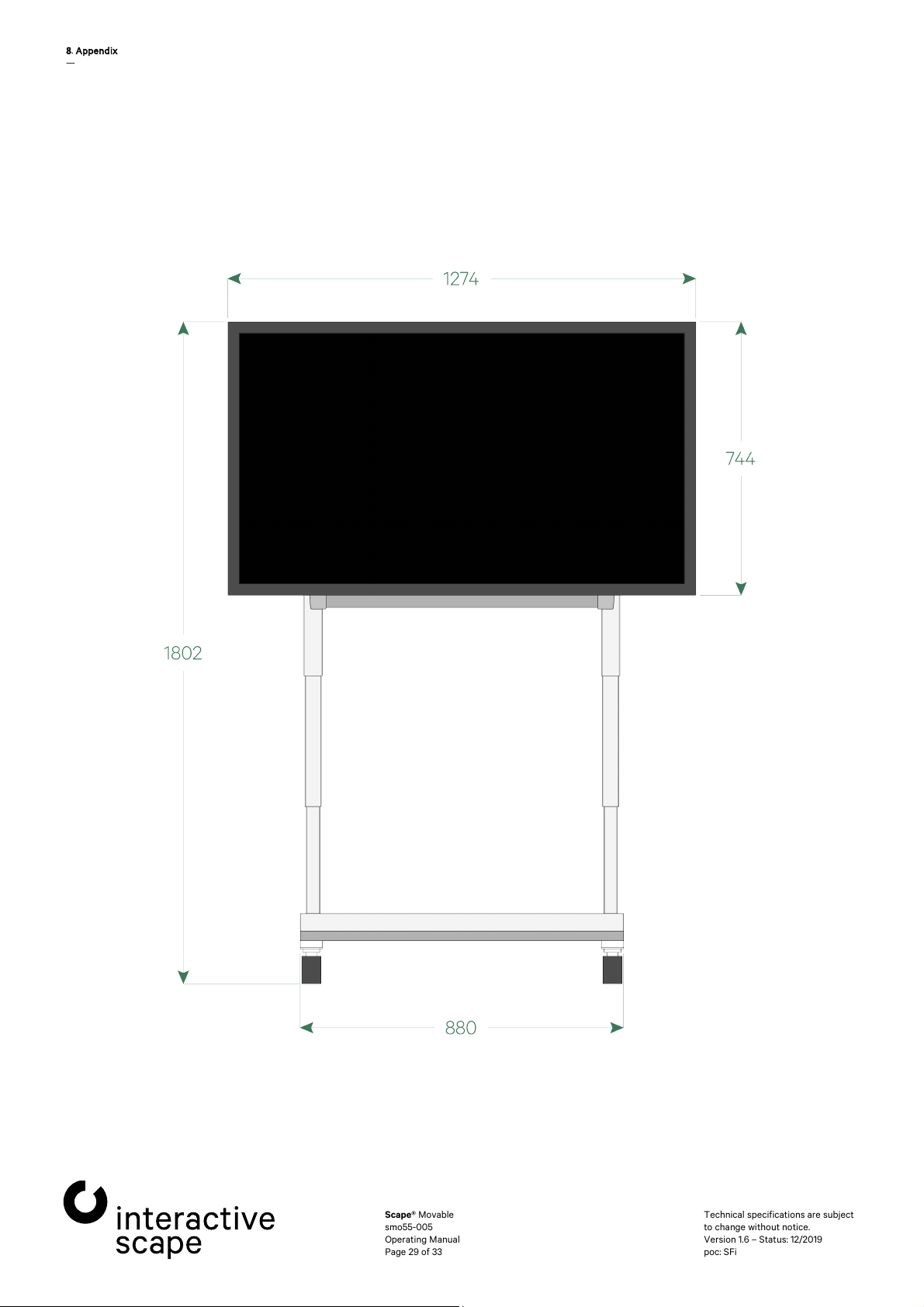
Dimensions when the screen is
vertical (LxWxH min/H max)
1278 x 700 x 1151/1802* mm
Weight
100 kg (+ max. 7.2 kg for frame)
Maximum power consumption
650 W
Power supply
230 V AC 50 Hz
Display diagonal
13
Resolution
3840 x 2160 (UHD)
Brightness (panel)
700 cd/m²
Contrast
11
Backlight
LED
Viewing angle
178° / 178°
Color gamut
1.07 billion
Latency
6
Backlight - lifetime
60,000 h
Pixel class
ISO 9241
Touch controller
3M – PCAP
80 touches
Palm recognition
Object recognition possible (Capore®)
Interfaces
Touch
HID USB
TUIO 1.1
Operating period
24 hours / 7 days
Max. ambient humidity
Operation
10 ~ 90 % (not condensing)
Storage
10 ~ 90 % (not condensing)
Max. ambient temperature
Operation
0 ~ 35 °C / 32 ~ 95 °F
Storage
-
Operating voltage
100
—
8. Appendix
8.1. Technical data
8.1.1. Scape® Movable
WxH min/H max)
* Due to manufacturing tolerances in the hydraulic systems, the maximum heights can deviate slightly.
8.1.2. Touch screen
88.0 mm (54.6")
(panel)
00:1
ms
-307 (Pixel Error Class II)
20 ~ 60 °C / -4 ~ 140 °F
– 240 VAC
Scape® Movable Technical specifications are subject
smo55-005 to change witho ut notice.
Operating Manua l Version 1.6 – Status: 12/2019
Page 20 of 33 poc: SFi

8. Appendix
Power draw
1
Dimensions (L x H x D)
1274 x 744 x 88 mm
Weight
49
Mounting
VESA 400x400 mm, 600x400 mm, 800x400 mm
Max. tipping angle
0°
Air flow
0.5 m³ / min
Material
Sheet steel
Powder coated (fine structure), deep black (RAL9005)
Specifications
Processor
Intel Core i5 Quad
RAM
16 GB
Hard drive
250 GB SSD Samsung M.2
Graphics card
NVIDIA Geforce RTX 2060 6GB
Ports
Display
2x HDMI 2.0
1x DisplayPort 1.4
Network
WLAN 802.11ac/b/g/n
Bluetooth 5.0
2x Gigabit Ethernet
USB 4
1x USB 3.1 type A
2
Other
Dimensions (LxWxH)
210 x 203 x 62 mm
Power supply
External power supply unit
Power draw
330W
Operating
Windows 10 Professional
—
30W
cooling
8.1.3. Silent PC
kg
- 180°
Core
system
x USB 3.0
x USB 3.1 type C
Scape® Movable Technical specifications are subject
smo55-005 to change witho ut notice.
Operating Manua l Version 1.6 – Status: 12/2019
Page 21 of 33 poc: SFi

8. Appendix
—
8.2. Technical Drawings
8.2.1. Perspective
Scape® Movable Technical specifications are subject
smo55-005 to change witho ut notice.
Operating Manua l Version 1.6 – Status: 12/2019
Page 22 of 33 poc: S Fi

8. Appendix
—
8.2.2. Horizontal – Top view
Scape® Movable Technical specifications are subject
smo55-005 to change witho ut notice.
Operating Manua l Version 1.6 – Status: 12/2019
Page 23 of 33 poc: SFi

8. Appendix
—
8.2.3. Horizontal – Front view (high)
Scape® Movable Technical specifications are subject
smo55-005 to change witho ut notice.
Operating Manua l Version 1.6 – Status: 12/2019
Page 24 of 33 poc: SFi

8. Appendix
—
8.2.4. Horizontal – Front view (low)
Scape® Movable Technical specifications are subject
smo55-005 to change witho ut notice.
Operating Manua l Version 1.6 – Status: 12/2019
Page 25 of 33 poc: SFi

8. Appendix
—
8.2.5. Horizontal – Right view (high)
Scape® Movable Technical specifications are subject
smo55-005 to change witho ut notice.
Operating Manua l Version 1.6 – Status: 12/2019
Page 26 of 33 poc: SFi

8. Appendix
—
8.2.6. Horizontal – Right view (low)
Scape® Movable Technical specifications are subject
smo55-005 to change witho ut notice.
Operating Manua l Version 1.6 – Status: 12/2019
Page 27 of 33 poc: SFi

8. Appendix
—
8.2.7. Vertical – Top view
Scape® Movable Technical specifications are subject
smo55-005 to change witho ut notice.
Operating Manua l Version 1.6 – Status: 12/2019
Page 28 of 33 poc: SFi
8. Appendix
—
8.2.8. Vertical – Front view (high)
Scape® Movable Technical specifications are subject
smo55-005 to change witho ut notice.
Operating Manua l Version 1.6 – Status: 12/2019
Page 29 of 33 poc: SFi

8. Appendix
—
8.2.9. Vertical – Front view (low)
Scape® Movable Technical specifications are subject
smo55-005 to change witho ut notice.
Operating Manua l Version 1.6 – Status: 12/2019
Page 30 of 33 poc: SFi

8. Appendix
—
8.2.10. Vertical – Right view (high)
Scape® Movable Technical specifications are subject
smo55-005 to change witho ut notice.
Operating Manua l Version 1.6 – Status: 12/2019
Page 31 of 33 poc: SFi

8. Appendix
—
8.2.11. Vertical – Right view (low)
Scape® Movable Technical specifications are subject
smo55-005 to change witho ut notice.
Operating Manua l Version 1.6 – Status: 12/2019
Page 32 of 33 poc: SFi

Interactive Scape GmbH
Wilhelmine-Gemberg-Weg 6, D-10179 Berlin
T +49 30 69 809 41-00, F +49 30 69 809 429
www.interactive-scape.com, info@interactive-scape.com
 Loading...