

Intepro systems PSI 9080-340 3U, PSI 9360-80 3U, PSI 9200-210 3U, PSI 9200-70 3U, PSI 9360-120 3U Operating Manual
...
Date: 09/2018
Operating Guide
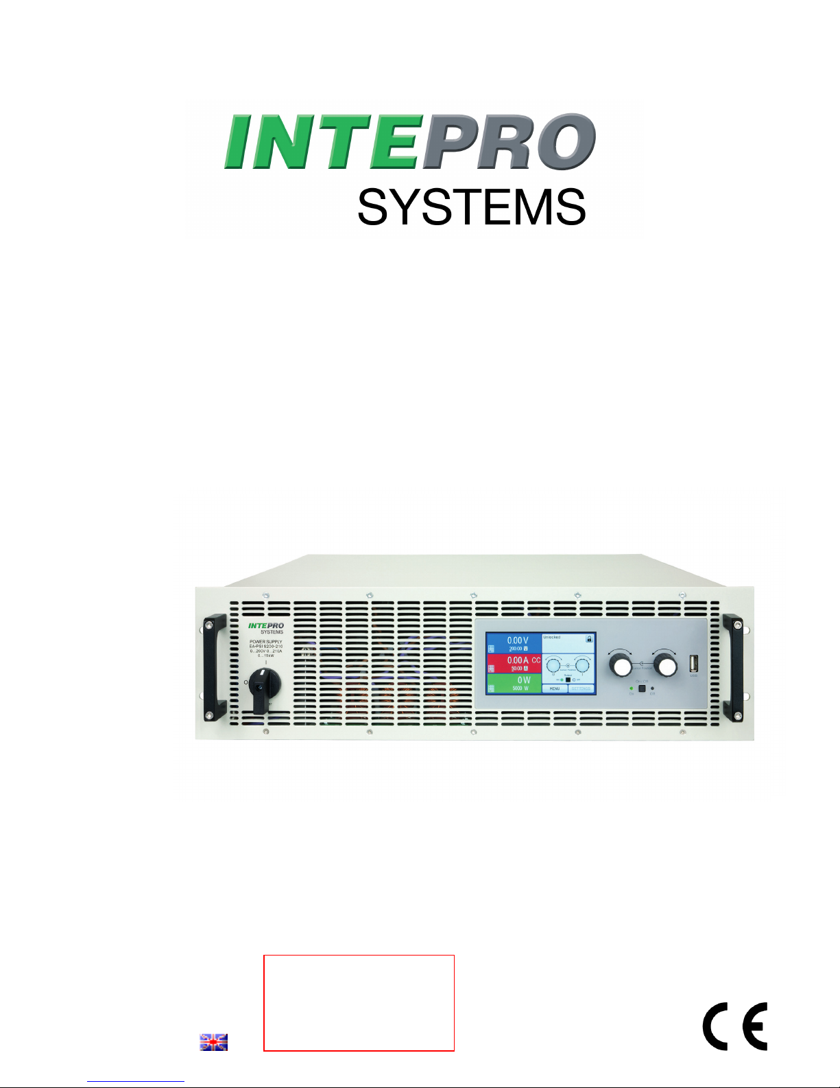
PSI 9000 3U
DC High Efficiency Power Supply
Attention! This document is
only valid for devices with TFT
display and rmware “KE: 2.24”
(standard models) resp. “KE:
2.08” (GPIB models), “HMI:
2.14” and “DR: 1.6.5” or higher.


Page 3
Intepro Systems
www.inteproate.com
service@inteproate.com
PSI 9000 3U Series
TABLE OF CONTENTS
1
. GENERAL
1.1 About this document ......................................5
1.1.1 Retention and use ..........................................5
1.1.2 Copyright ........................................................5
1.1.3 Validity ............................................................5
1.1.4 Symbols and warnings ..................................5
1.2 Warranty .........................................................5
1.3 Limitation of liability ........................................5
1.4 Disposal of equipment ...................................6
1.5 Product key ....................................................6
1.6 Intended usage ..............................................6
1.7 Safety .............................................................7
1.7.1 Safety notices .................................................7
1.7.2 Responsibility of the user...............................8
1.7.3 Responsibility of the operator .......................8
1.7.4 User requirements .........................................8
1.7.5 Alarm signals ..................................................9
1.8 Technical Data ...............................................9
1.8.1 Approved operating conditions ......................9
1.8.2 General technical data ...................................9
1.8.3 Specic technical data (400 V AC models) . 10
1.8.4 Specic technical data (208 V AC models) . 20
1.8.5 Views ............................................................28
1.8.6 Control elements ..........................................32
1.9 Construction and function ............................33
1.9.1 General description ......................................33
1.9.2 Block diagram ..............................................33
1.9.3 Scope of delivery .........................................34
1.9.4 Accessories ..................................................34
1.9.5 Options .........................................................34
1.9.6 The control panel (HMI) ...............................35
1.9.7 USB port type B (rear side) .........................38
1.9.8 Interface module slot ...................................38
1.9.9 Analog interface ...........................................38
1.9.10 “Share” connector ........................................39
1.9.11 “Sense” connector (remote sensing) ...........39
1.9.12 Master-Slave bus .........................................39
1.9.13 GPIB port (optional) .....................................39
2
. INSTALLATION &
COMMISSIONING
2.1 Transport and storage .................................40
2.1.1 Transport ......................................................40
2.1.2 Packaging ....................................................40
2.1.3 Storage .........................................................40
2.2 Unpacking and visual check ........................40
2.3 Installation ....................................................40
2.3.1 Safety procedures before installation and
use ................................................................40
2.3.2 Preparation ...................................................40
2.3.3 Installing the device .....................................41
2.3.4 Connection to AC supply .............................42
2.3.5 Connection to DC loads ...............................45
2.3.6 Grounding of the DC output ........................46
2.3.7 Connecting the analog interface .................46
2.3.8 Connection of remote sense .......................46
2.3.9 Installation of an interface module ...............47
2.3.10 Connecting the “Share” bus ........................48
2.3.11 Connecting the USB port (rear side) ...........48
2.3.12 Initial commission .........................................48
2.3.13 Commission after a rmware update or a
long period of non-use .................................48
2.3.14 System extension with slave units ..............49
3
. OPERATION AND APPLICATION
3.1 Personal safety ............................................50
3.2 Operating modes .........................................50
3.2.1 Voltage regulation / Constant voltage .........50
3.2.2 Current regulation / constant current / current
limiting ..........................................................51
3.2.3 Power regulation / constant power / power
limiting ..........................................................51
3.2.4 Internal resistance regulation ......................51
3.3 Alarm conditions ..........................................52
3.3.1 Power Fail ...................................................52
3.3.2 Overtemperature ..........................................52
3.3.3 Overvoltage protection.................................52
3.3.4 Overcurrent protection .................................52
3.3.5 Overpower protection ..................................52
3.4 Manual operation .........................................53
3.4.1 Switching on the device ...............................53
3.4.2 Switching o the device ...............................53
3.4.3 Conguration via MENU ..............................53
3.4.4 Adjustment limits ..........................................62
3.4.5 Changing the operating mode .....................62
3.4.6 Manual adjustment of set values .................63
3.4.7 Switching the main screen view ..................63
3.4.8 The meter bars .............................................64
3.4.9 Switching the DC output on or o ...............64
3.4.10 Recording to USB stick (logging) ................65
3.5 Remote control .............................................66
3.5.1 General .........................................................66
3.5.2 Control locations ..........................................66
3.5.3 Remote control via a digital interface ..........66
3.5.4 Remote control via the analog interface
(AI) ................................................................67
3.6 Alarms and monitoring .................................71
3.6.1 Denition of terms ........................................71
3.6.2 Device alarm and event handling ................71
3.7 Control panel (HMI) lock ..............................73
3.8 Limits lock .....................................................73
3.9 Loading and saving a user prole ...............74
3.10 The function generator.................................75
3.10.1 Introduction...................................................75

Page 4
Intepro Systems
www.inteproate.com
service@inteproate.com
PSI 9000 3U Series
3.10.2 General .........................................................75
3.10.3 Method of operation .....................................76
3.10.4 Manual operation .........................................76
3.10.5 Sine wave function .......................................77
3.10.6 Triangular function .......................................78
3.10.7 Rectangular function ....................................78
3.10.8 Trapezoidal function .....................................79
3.10.9 DIN 40839 function ......................................79
3.10.10 Arbitrary function ..........................................80
3.10.11 Ramp function ..............................................84
3.10.12 UI and IU table functions (XY table) ............84
3.10.13 PV table function (photovoltaics) .................86
3.10.14 FC table function (fuel cell) ..........................87
3.10.15 Extended PV table function according to EN
50530 ...........................................................89
3.10.16 Remote control of the function generator....94
3.11 Other applications ........................................95
3.11.1 Parallel operation in master-slave (MS) ......95
3.11.2 Series connection ........................................99
3.11.3 Operation as battery charger .......................99
3.11.4 Two quadrants operation (2QO) ................100
4
. SERVICE AND MAINTENANCE
4.1 Maintenance / cleaning ..............................102
4.2 Fault nding / diagnosis / repair.................102
4.2.1 Firmware updates ......................................102
4.3 Calibration ..................................................103
4.3.1 Preface .......................................................103
4.3.2 Preparation .................................................103
4.3.3 Calibration procedure ................................103
5
. CONTACT AND SUPPORT
5.1 General .......................................................105
5.2 Contact options ..........................................105

Page 5
Intepro Systems
www.inteproate.com
service@inteproate.com
PSI 9000 3U Series
1. General
1.1 About this document
1.1.1 Retention and use
This document is to be kept in the vicinity of the equipment for future reference and explanation of the operation of
the device. This document is to be delivered and kept with the equipment in case of change of location and/or user.
1.1.2 Copyright
Reprinting, copying, also partially, usage for other purposes as foreseen of this manual are forbidden and breach
may lead to legal process.
1.1.3 Validity
This manual is valid for the following equipment including derived variants:
Model Article nr.. Model Article nr.. Model Article nr..
PSI 9040-170 3U 06230350 PSI 9080-340 3U 06230357 PSI 9080-510 3U 06230364
PSI 9080-170 3U 06230351 PSI 9200-140 3U 06230358 PSI 9200-210 3U 06230365
PSI 9200-70 3U 06230352 PSI 9360-80 3U 06230359 PSI 9360-120 3U 06230366
PSI 9360-40 3U 06230353 PSI 9500-60 3U 06230360 PSI 9500-90 3U 06230367
PSI 9500-30 3U 06230354 PSI 9750-40 3U 06230361 PSI 9750-60 3U 06230368
PSI 9750-20 3U 06230355 PSI 91000-30 3U 06230362 PSI 91500-30 3U 06230369
PSI 9040-340 3U 06230356 PSI 9040-510 3U 06230363
Changes and modications for special models will be listed in a separate document.
1.1.4 Symbols and warnings
Warning and safety notices as well as general notices in this document are shown in a box with a symbol as follows:
Symbol for a life threatening danger
Symbol for general safety notices (instructions and damage protection bans) or important infor-
mation for operation
Symbol for general notices
1.2 Warranty
Intepro Systems guarantees the functional competence of the applied technology and the stated performance
parameters. The warranty period begins with the delivery of free from defects equipment.
Terms of guarantee are included in the general terms and conditions (TOS) of Intepro Systems.
1.3 Limitation of liability
All statements and instructions in this manual are based on current norms and regulations, up-to-date technology
and our long term knowledge and experience. The manufacturer accepts no liability for losses due to:
• Usage for purposes other than designed
• Use by untrained personnel
• Rebuilding by the customer
• Technical changes
• Use of not authorized spare parts
The actual delivered device(s) may dier from the explanations and diagrams given here due to latest technical
changes or due to customized models with the inclusion of additionally ordered options.
Page 6
Intepro Systems
www.inteproate.com
service@inteproate.com
PSI 9000 3U Series
1.4 Disposal of equipment
A piece of equipment which is intended for disposal must, according to local laws and regulations be returned to
the manufacturer for scrapping, unless the person operating the piece of equipment or another, delegated person
is conducting the disposal. Our equipment falls under these regulations and is accordingly marked with the following symbol:
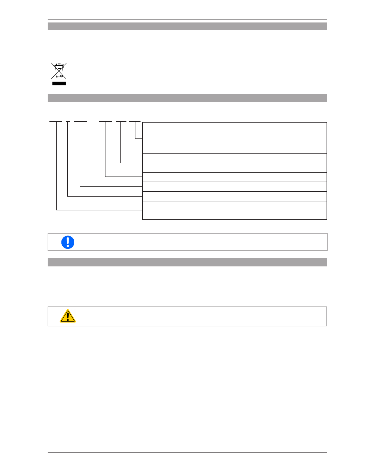
1.5 Product key
Decoding of the product description on the label, using an example:
PSI 9 080 - 510 3U zzz
Field for identication of installed options and/or special models
3W = Option 3W installed (GPIB port instead of Interface slot)
HS = High Speed option installed
WC = Water cooling installed
Construction (not always given)
3U = 19" frame with 3U
Maximum current of the device in Ampere
Maximum voltage of the device in Volt
Series: 9 = Series 9000
Type identication:
PSI = Power Supply Intelligent, always programmable
Special models are always derived from standard models and can vary in input voltage and
current from those given.
1.6 Intended usage
The equipment is intended to be used, if a power supply or battery charger, only as a variable voltage and current
source, or, if an electronic load, only as a variable current sink.
Typical application for a power supply is DC supply to any relevant user, for a battery charger the charging of various battery types and for electronic loads the replacement of an ohmic resistor by an adjustable DC current sink
in order to load relevant voltage and current sources of any type.
• Claims of any sort due to damage caused by non-intended usage will not be accepted.
• All damage caused by non-intended usage is solely the responsibility of the operator.
Page 7
Intepro Systems
www.inteproate.com
service@inteproate.com
PSI 9000 3U Series
1.7 Safety
1.7.1 Safety notices
Mortal danger - Hazardous voltage
• Electrical equipment operation means that some parts can be under dangerous voltage.
Therefore all parts under voltage must be covered! This basically applies to all models,
though 40 V models according to SELV can’t generate hazardous DC voltage.
• All work on connections must be carried out under zero voltage (output not connected
to load) and may only be performed by qualied and informed persons. Improper actions can cause fatal injury as well as serious material damage.
• Never touch cables or connectors directly after unplugging from mains supply as the
danger of electric shock remains!
• Never touch the contacts on the DC output terminal directly after switching o the DC
output, because there still can dangerous voltage present, sinking more or less slowly
depending on the load! There also can be dangerous potential between negative DC
output to PE or positive DC output to PE due to charged X capacitors which may not
discharge.
• Always follow 5 safety rules when working with electric devices:
• Disconnect completely
• Secure against reconnection
• Verify that the system is dead
• Carry out earthing and short-circuiting
• Provide protection from adjacent live parts
• The equipment must only be used as intended
• The equipment is only approved for use within the connection limits stated on the product label.
• Do not insert any object, particularly metallic, through the ventilator slots
• Avoid any use of liquids near the equipment. Protect the device from wet, damp and conden-
sation.
• For power supplies and battery chargers: do not connect users, particularly low resistance, to
devices under power; sparking may occur which can cause burns as well as damage to the
equipment and to the user.
• For electronic loads: do not connect power sources to equipment under power, sparking may
occur which can cause burns as well as damage to the equipment and to the source.
• ESD regulations must be applied when plugging interface cards or modules into the relative slot
• Interface cards or modules may only be attached or removed after the device is switched o.
It is not necessary to open the device.
• Do not connect external power sources with reversed polarity to DC input or outputs! The
equipment will be damaged.
• For power supply devices: avoid where possible connecting external power sources to the DC
output, and never those that can generate a higher voltage than the nominal voltage of the device.
• For electronic loads: do not connect a power source to the DC input which can generate a voltage more than 120% of the nominal input voltage of the load. The equipment is not protected
against over voltage and may be irreparably damaged.
• Never insert a network cable which is connected to Ethernet or its components into the masterslave socket on the back side of the device!
• Always congure the various protecting features against overvoltage etc. for sensitive loads to
what the target application requires!
Page 8
Intepro Systems
www.inteproate.com
service@inteproate.com
PSI 9000 3U Series
1.7.2 Responsibility of the user
The equipment is in industrial operation. Therefore the operators are governed by the legal safety regulations.
Alongside the warning and safety notices in this manual the relevant safety, accident prevention and environmental
regulations must also be applied. In particular the users of the equipment:
• must be informed of the relevant job safety requirements
• must work to the dened responsibilities for operation, maintenance and cleaning of the equipment
• before starting work must have read and understood the operating manual
• must use the designated and recommended safety equipment.
Furthermore, anyone working with the equipment is responsible for ensuring that the device is at all times technically t for use.
1.7.3 Responsibility of the operator
Operator is any natural or legal person who uses the equipment or delegates the usage to a third party, and is
responsible during its usage for the safety of the user, other personnel or third parties.
The equipment is in industrial operation. Therefore the operators are governed by the legal safety regulations.
Alongside the warning and safety notices in this manual the relevant safety, accident prevention and environmental
regulations must also be applied. In particular the operator has to
• be acquainted with the relevant job safety requirements
• identify other possible dangers arising from the specic usage conditions at the work station via a risk assessment
• introduce the necessary steps in the operating procedures for the local conditions
• regularly control that the operating procedures are current
• update the operating procedures where necessary to reect changes in regulation, standards or operating con-
ditions.
• dene clearly and unambiguously the responsibilities for operation, maintenance and cleaning of the equipment.
• ensure that all employees who use the equipment have read and understood the manual. Furthermore the users
are to be regularly schooled in working with the equipment and the possible dangers.
• provide all personnel who work with the equipment with the designated and recommended safety equipment
Furthermore, the operator is responsible for ensuring that the device is at all times technically t for use.
1.7.4 User requirements
Any activity with equipment of this type may only be performed by persons who are able to work correctly and
reliably and satisfy the requirements of the job.
• Persons whose reaction capability is negatively inuenced by e.g. drugs, alcohol or medication may not operate
the equipment.
• Age or job related regulations valid at the operating site must always be applied.
Danger for unqualied users
Improper operation can cause person or object damage. Only persons who have the necessary training, knowledge and experience may use the equipment.
Delegated persons are those who have been properly and demonstrably instructed in their tasks and the atten-
dant dangers.
Qualied persons are those who are able through training, knowledge and experience as well as knowledge of
the specic details to carry out all the required tasks, identify dangers and avoid personal and other risks.
All work on electrical equipment may only be performed by qualied electricians.
Page 9
Intepro Systems
www.inteproate.com
service@inteproate.com
PSI 9000 3U Series
1.7.5 Alarm signals
The equipment oers various possibilities for signalling alarm conditions, however, not for danger situations. The
signals may be optical (on the display as text), acoustic (piezo buzzer) or electronic (status output of the analog
interface). All alarms will cause the device to switch o the DC output.
The meaning of the signals is as follows:
Signal OT
(OverTemperature)
• Overheating of the device
• DC output will be switched o
• Non-critical
Signal OVP
(OverVoltage)
• Overvoltage shutdown of the DC output due to high voltage entering the device or generated by the device itself due to a defect
• Critical! The device and/or the load could be damaged
Signal OCP
(OverCurrent)
• Shutdown of the DC output due to excess of the preset limit
• Non-critical, protects the load from excessive current consumption
Signal OPP
(OverPower)
• Shutdown of the DC output due to excess of the preset limit
• Non-critical, protects the load from excessive power consumption
Signal PF
(Power Fail)
• DC output shutdown due to AC undervoltage or defect in the AC input
• Critical on overvoltage! AC input circuit could be damaged
1.8 Technical Data
1.8.1 Approved operating conditions
• Use only inside dry buildings
• Ambient temperature 0-50°C
• Operational altitude: max. 2000 m above sea level
• Max 80% relative humidity, not condensing
1.8.2 General technical data
Display: Colour TFT touch screen with gorilla glass, 4.3”, 480pt x 272pt, capacitive
Controls: 2 rotary knobs with pushbutton function, 1 pushbutton
The nominal values for the device determine the maximum adjustable ranges.

Page 10
Intepro Systems
www.inteproate.com
service@inteproate.com
PSI 9000 3U Series
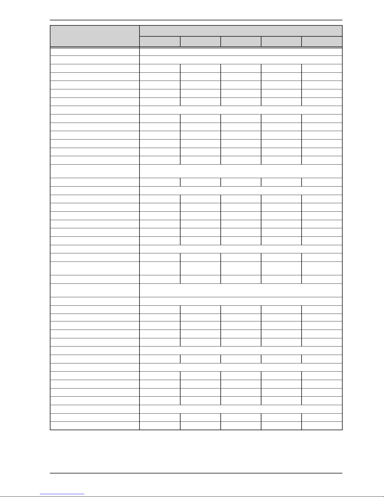
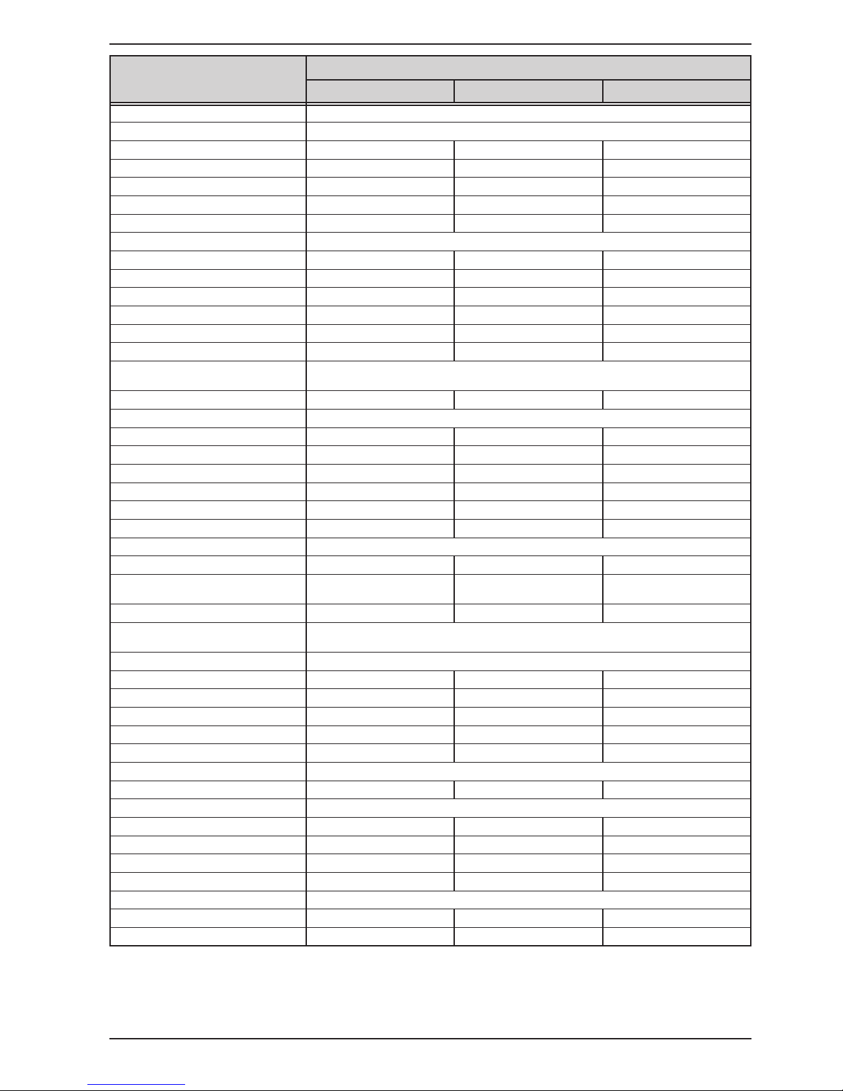
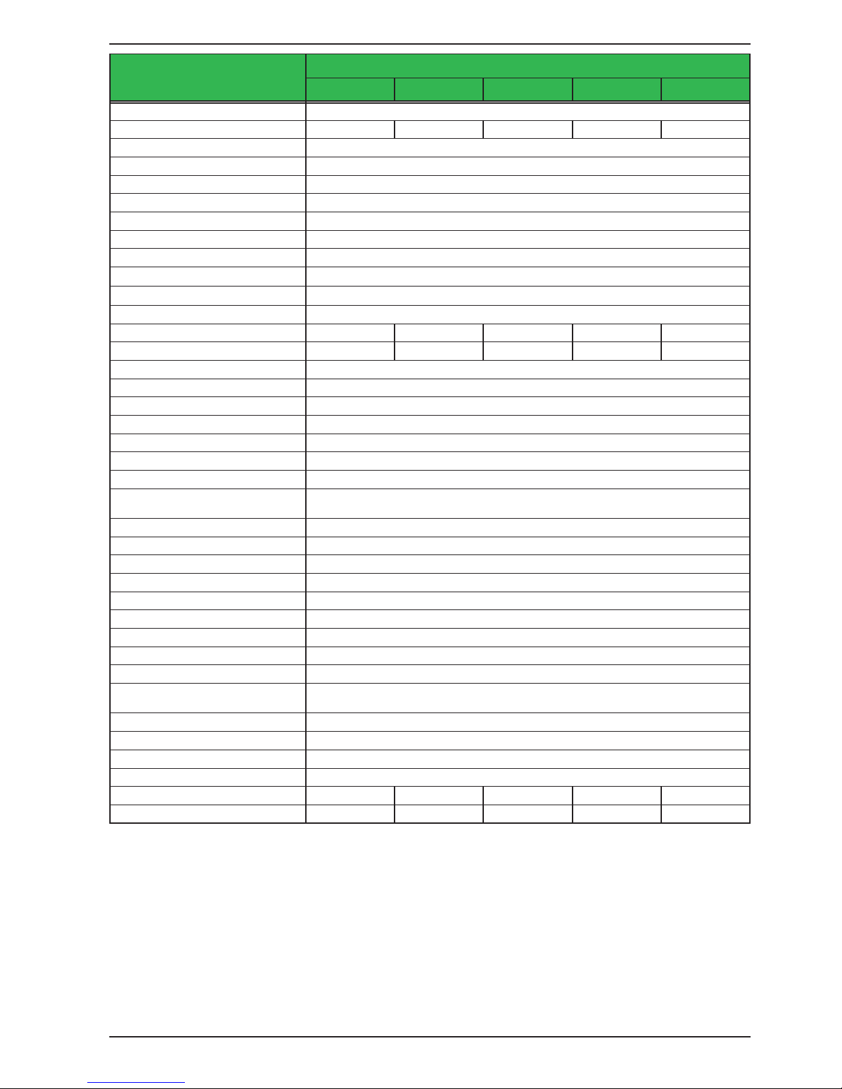
1.8.3 Specic technical data (400 V AC models)
(1 Related to the nominal values, the accuracy denes the maximum deviation between an adjusted values and the true (actual) value.
Example: a 80 V model has min. 0.1% voltage accuracy, that is 80 mV. When adjusting the voltage to 5 V, the actual value is allowed to dier max. 80 mV, which
means it might be between 4.92 V and 5.08 V.
(2 RMS value: LF 0...300 kHz, PP value: HF 0...20MHz
(3 Typical value at 100% output voltage and 100% power
(4 The display error adds to the error of the related actual value on the DC output
3.3 kW / 5 kW
Model
PSI 9040-170 PSI 9080-170 PSI 9200-70 PSI 9360-40 PSI 9500-30
AC Input
Voltage (L-L), Frequency 340...460 V AC, 45 - 65 Hz
Connection 2ph, PE 2ph, PE 2ph, PE 2ph, PE 2ph, PE
Fusing (internal) 2x T16 A 2x T16 A 2x T16 A 2x T16 A 2x T16 A
Leak current < 3.5 mA < 3.5 mA < 3.5 mA < 3.5 mA < 3.5 mA
Power factor > 0.99 > 0.99 > 0.99 > 0.99 > 0.99
DC Output
Max. output voltage U
Max
40 V 80 V 200 V 360 V 500 V
Max. output current I
Max
170 A 170 A 70 A 40 A 30 A
Max. output power P
Max
3.3 kW 5 kW 5 kW 5 kW 5 kW
Overvoltage protection range 0...44 V 0...88 V 0...220 V 0...396 V 0...550 V
Overcurrent protection range 0...187 A 0...187 A 0...77 A 0...44 A 0...33 A
Overpower protection range 0…3.63 kW 0…5.50 kW 0…5.50 kW 0…5.50 kW 0…5.50 kW
Temperature coecient for set
values Δ/K
Voltage / current: 100 ppm
Output capacitance (approx.) 8500 μF 8500 μF 2500 μF 400 μF 250 μF
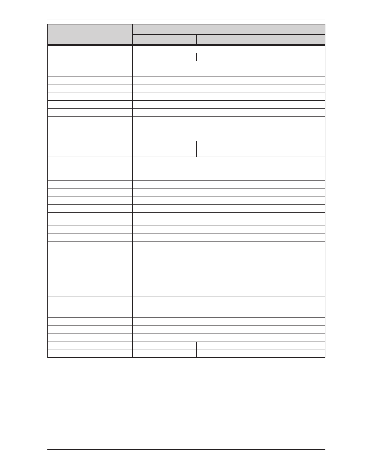
Voltage regulation
Adjustment range 0...40.8 V 0...81.6 V 0...204 V 0...367.2 V 0...510 V
Accuracy
(1
(at 23 ± 5°C) < 0.1% U
Max
< 0.1% U
Max
< 0.1% U
Max
< 0.1% U
Max
< 0.1% U
Max
Line regulation at ±10% ΔU
AC
< 0.02% U
Max
< 0.02% U
Max
< 0.02% U
Max
< 0.02% U
Max
< 0.02% U
Max
Load regulation at 0...100% load < 0.05% U
Max
< 0.05% U
Max
< 0.05% U
Max
< 0.05% U
Max
< 0.05% U
Max
Rise time 10...90% ΔU Max. 30 ms Max. 30 ms Max. 30 ms Max. 30 ms Max. 30 ms
Transient time after load step < 1.5 ms < 1.5 ms < 1.5 ms < 1.5 ms < 1.5 ms
Display: Resolution See section „1.9.6.4. Resolution of the displayed values“
Display: Accuracy
(4
≤ 0.2% U
Max
≤ 0.2% U
Max
≤ 0.2% U
Max
≤ 0.2% U
Max
≤ 0.2% U
Max
Ripple
(2
< 200 mVPP
< 16 mV
RMS
< 200 mVPP
< 16 mV
RMS
< 300 mVPP
< 40 mV
RMS
< 550 mVPP
< 65 mV
RMS
< 350 mVPP
< 70 mV
RMS
Remote sensing compensation Max. 5% U
Max
Max. 5% U
Max
Max. 5% U
Max
Max. 5% U
Max
Max. 5% U
Max
Fall time at no load after switching
DC output o
Down from 100% to <60 V: less than 10 s
Current regulation
Adjustment range 0...173.4 A 0...173.4 A 0...71.4 A 0...40.8 A 0...30.6 A
Accuracy
(1
(at 23 ± 5°C) < 0.2% I
Max
< 0.2% I
Max
< 0.2% I
Max
< 0.2% I
Max
< 0.2% I
Max
Line regulation at ±10% ΔU
AC
< 0.05% I
Max
< 0.05% I
Max
< 0.05% I
Max
< 0.05% I
Max
< 0.05% I
Max
Load regulation at 0...100% ΔU
OUT
< 0.15% I
Max
< 0.15% I
Max
< 0.15% I
Max
< 0.15% I
Max
< 0.15% I
Max
Ripple
(2
< 80 mA
RMS
< 80 mA
RMS
< 22 mA
RMS
< 5.2 mA
RMS
< 16 mA
RMS
Display: Resolution See section „1.9.6.4. Resolution of the displayed values“
Display: Accuracy
(4
≤ 0.2% I
Max
≤ 0.2% I
Max
≤ 0.2% I
Max
≤ 0.2% I
Max
≤ 0.2% I
Max
Power regulation
Adjustment range 0…3.37 kW 0…5.1 kW 0…5.1 kW 0…5.1 kW 0…5.1 kW
Accuracy
(1
(at 23 ± 5°C) < 1% P
Max
< 1% P
Max
< 1% P
Max
< 1% P
Max
< 1% P
Max
Line regulation at ±10% ΔU
AC
< 0.05% P
Max
< 0.05% P
Max
< 0.05% P
Max
< 0.05% P
Max
< 0.05% P
Max
Load reg. at 10-90% ΔU
OUT
* ΔI
OUT
< 0.75% P
Max
< 0.75% P
Max
< 0.75% P
Max
< 0.75% P
Max
< 0.75% P
Max
Display: Resolution See section „1.9.6.4. Resolution of the displayed values“
Display: Accuracy
(4
≤ 0.75% P
Max
≤ 0.8% P
Max
≤ 0.8% P
Max
≤ 0.8% P
Max
≤ 0.8% P
Max
Eciency
(3
~ 93% ~ 93% ~ 95% ~ 95% ~ 95,5%

Page 11
Intepro Systems
www.inteproate.com
service@inteproate.com
PSI 9000 3U Series
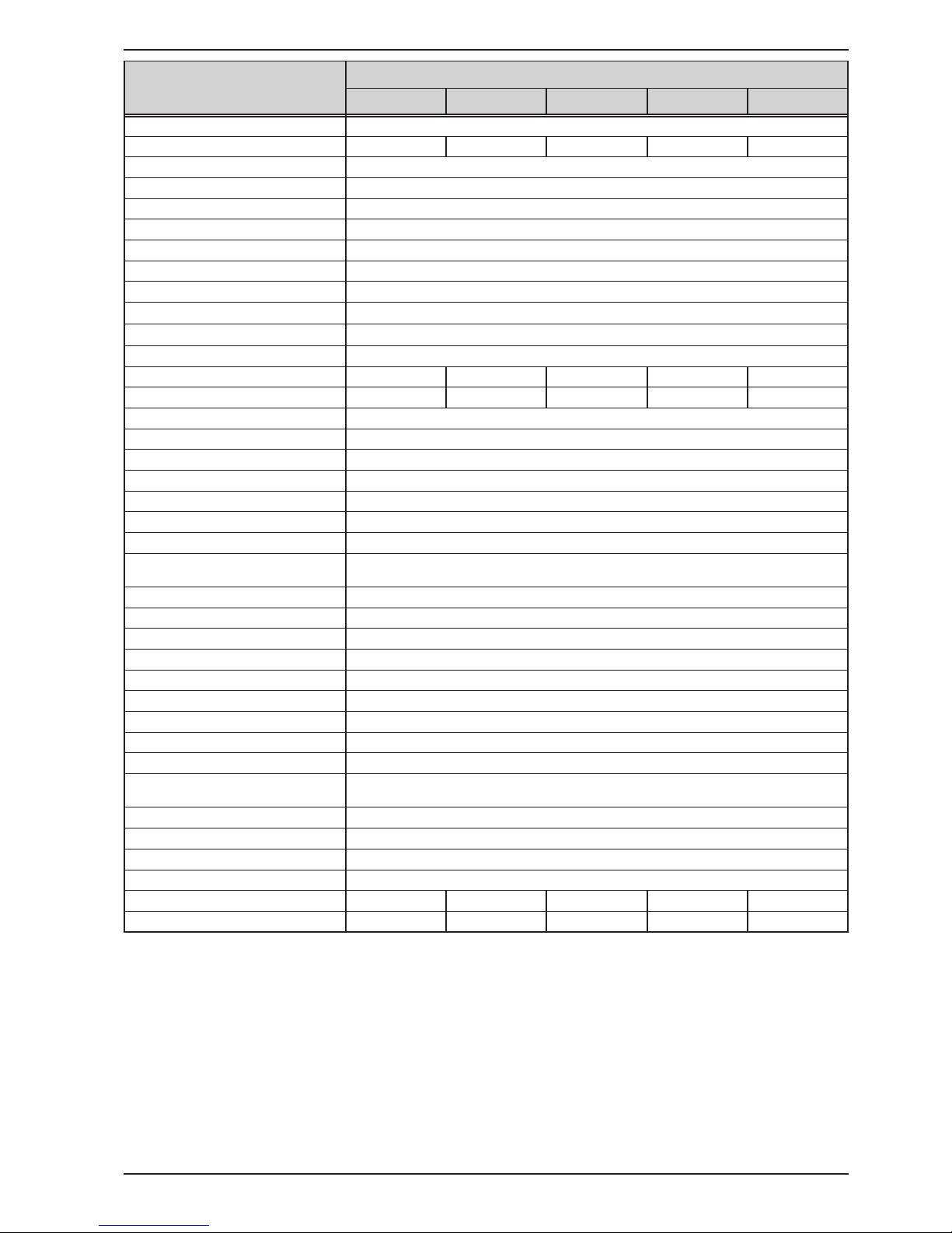
3.3 kW / 5 kW
Model
PSI 9040-170 PSI 9080-170 PSI 9200-70 PSI 9360-40 PSI 9500-30
Internal resistance regulation
Adjustment range 0...7 Ω 0...14 Ω 0...85 Ω 0...270 Ω 0...500 Ω
Accuracy
(1
≤2% of max. resistance ± 0.3% of rated current
Display: Resolution See section „1.9.6.4. Resolution of the displayed values“
Analog interface
(2
Set value inputs U, I, P, R
Actual value output U, I
Control signals DC on/o, remote control on/o, resistance mode on/o
Status signals CV, OVP, OT
Galvanic isolation to the device Max. 1500 V DC
Sample rate of inputs & outputs 500 Hz
Insulation Allowed oat (potential shift) on the DC output:
Negative terminal to PE Max. ±400 V DC ±400 V DC ±400 V DC ±400 V DC ±725 V DC
Positive terminal to PE Max. ±400 V DC ±400 V DC ±600 V DC ±600 V DC ±1000 V DC
AC input <-> PE 2.5 kV DC
AC input <-> DC output 2.5 kV DC
Miscellaneous
Cooling Temperature controlled fans, front inlet, rear exhaust
Ambient temperature 0..50°C (32...122°F)
Storage temperature -20...70°C (-4...158°F)
Humidity < 80%, not condensing
Standards
IEC 61010:2010
EMC TÜV approved acc. IEC 61000-6-2:2005 and IEC 61000-6-3:2006 Class B
Overvoltage category 2
Protection class 1
Pollution degree 2
Operational altitude < 2000 m (1.242 mi)
Digital interfaces
Featured 1x USB-B for communication, 1x USB-A for functions, 1x GPIB (optional)
Slot (standard version) optional: CANopen, Probus, Pronet, RS232, CAN, Ethernet, ModBus TCP
Galvanic isolation from device Max. 1500 V DC
Terminals
Rear side
Share Bus, DC output, AC input, remote sensing, analog interface, USB-B, master-
slave bus, interface module slot
Front side USB-A
Dimensions
Enclosure (WxHxD) 19“ x 3U x 609 mm (24”)
Total (WxHxD) 483 x 133 x 714 mm (19” x 5.2” x 28.1”)
Weight ~ 17 kg (37.5 lb) ~ 17 kg (37.5 lb) ~ 17 kg (37.5 lb) ~ 17 kg (37.5 lb) ~ 17 kg (37.5 lb)
Article number
(3
06230350 06230351 06230352 06230353 06230354
(1 Related to the nominal values, the accuracy denes the maximum deviation between an adjusted values and the true (actual) value
(2 For technical specications of the analog interface see „3.5.4.4 Analog interface specication“ on page 68
(3 Article number of the standard version, devices with options will have a dierent number
Page 12
Intepro Systems
www.inteproate.com
service@inteproate.com
PSI 9000 3U Series
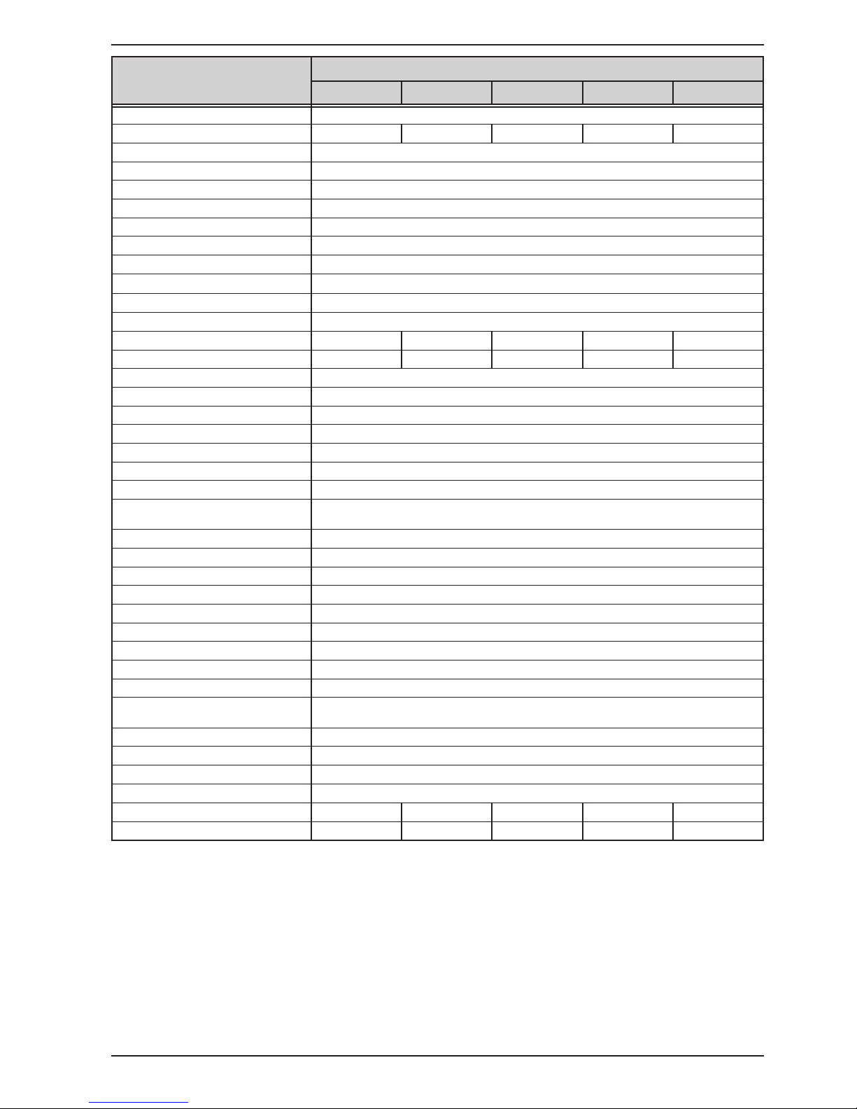
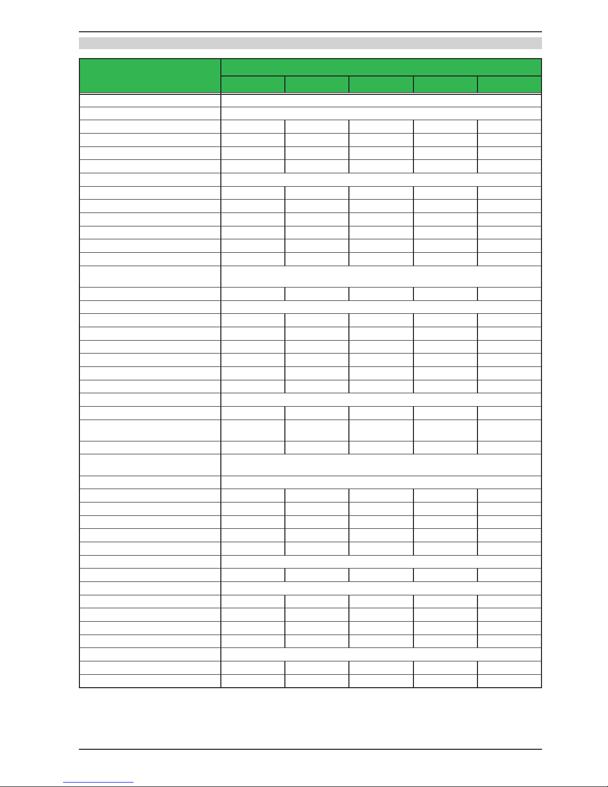
5 kW / 6.6 kW / 10 kW
Model
PSI 9750-20 PSI 9040-340 PSI 9040-510 PSI 9080-340 PSI 9200-140
AC Input
Voltage (L-L) 340...460 V AC
Connection 2ph,PE 3ph,PE 3ph,PE 3ph,PE 3ph,PE
Frequency 45 - 65 Hz 45 - 65 Hz 45 - 65 Hz 45 - 65 Hz 45 - 65 Hz
Fusing (internal) 2x T16 A 4x T16 A 6x T16 A 4x T16 A 4x T16 A
Leak current < 3.5 mA < 3.5 mA < 3.5 mA < 3.5 mA < 3.5 mA
Power factor > 0.99 > 0.99 > 0.99 > 0.99 > 0.99
DC Output
Max. output voltage U
Max
750 V 40 V 40 V 80 V 200 V
Max. output current I
Max
20 A 340 A 510 A 340 A 140 A
Max. output power P
Max
5 kW 6.6 kW 10 kW 10 kW 10 kW
Overvoltage protection range 0...825 V 0...44 V 0...44 V 0...88 V 0...220 V
Overcurrent protection range 0...22 A 0...374 A 0...561 A 0...374 A 0...154 A
Overpower protection range 0…5.50 kW 0…7.26 kW 0…11.00 kW 0…11.00 kW 0…11.00 kW
Temperature coecient for set
values Δ/K
Voltage / current: 100 ppm
Output capacitance (approx.) 100 μF 16900 μF 25380 μF 16900 μF 5040 μF
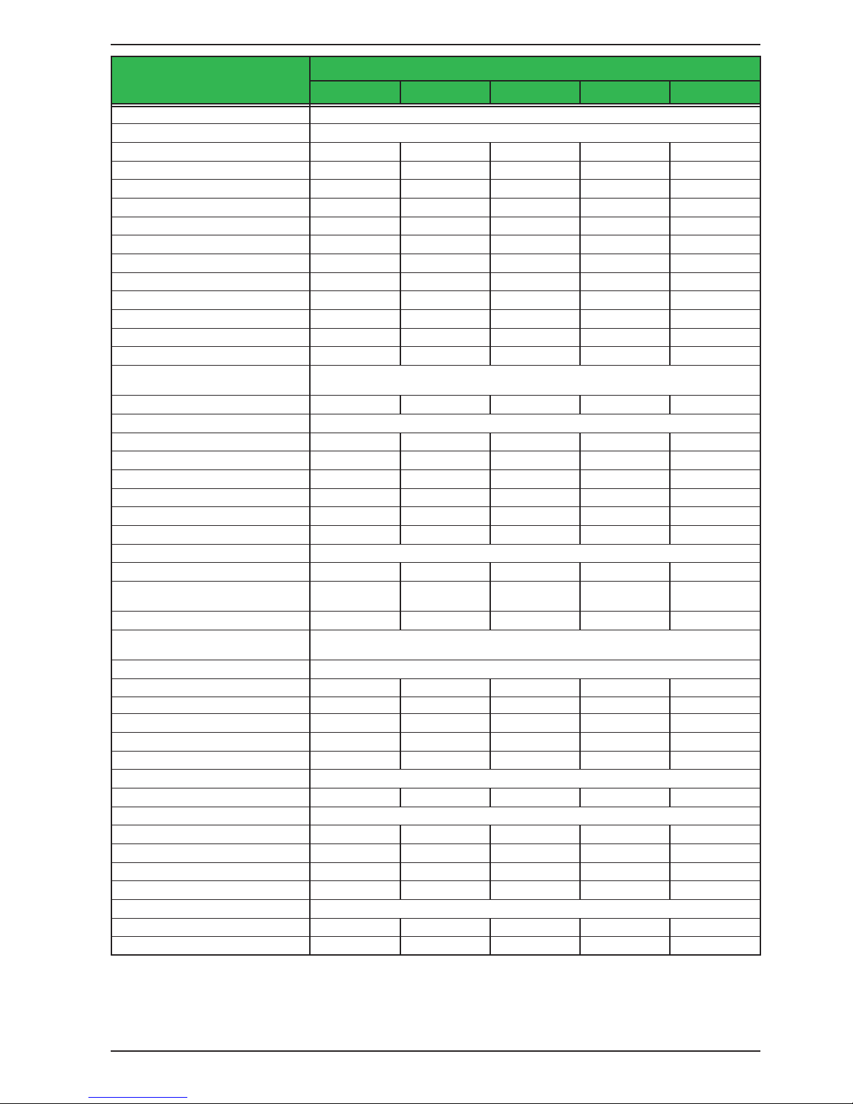
Voltage regulation
Adjustment range 0...765 V 0...40.8 V 0...40.8 V 0...81.6 V 0...204 V
Accuracy
(1
(at 23 ± 5°C) < 0.1% U
Max
< 0.1% U
Max
< 0.1% U
Max
< 0.1% U
Max
< 0.1% U
Max
Line regulation at ±10% ΔU
AC
< 0.02% U
Max
< 0.02% U
Max
< 0.02% U
Max
< 0.02% U
Max
< 0.02% U
Max
Load regulation at 0...100% load < 0.05% U
Max
< 0.05% U
Max
< 0.05% U
Max
< 0.05% U
Max
< 0.05% U
Max
Rise time 10...90% ΔU Max. 30 ms Max. 30 ms Max. 30 ms Max. 30 ms Max. 30 ms
Transient time after load step < 1.5 ms < 1.5 ms < 1.5 ms < 1.5 ms < 1.5 ms
Display: Resolution See section „1.9.6.4. Resolution of the displayed values“
Display: Accuracy
(4
≤ 0.2% U
Max
≤ 0.2% U
Max
≤ 0.2% U
Max
≤ 0.2% U
Max
≤ 0.2% U
Max
Ripple
(2
< 800 mVPP
< 200 mV
RMS
< 320 mVPP
< 25 mV
RMS
< 320 mVPP
< 25 mV
RMS
< 320 mVPP
< 25 mV
RMS
< 300 mVPP
< 40 mV
RMS
Remote sensing compensation Max. 5% U
Max
Max. 5% U
Max
Max. 5% U
Max
Max. 5% U
Max
Max. 5% U
Max
Fall time at no load after switching
DC output o
Down from 100% to <60 V: less than 10 s
Current regulation
Adjustment range 0...20.4 A 0...346.8 A 0...520.2 A 0...346.8 A 0...142.8 A
Accuracy
(1
(at 23 ± 5°C) < 0.2% I
Max
< 0.2% I
Max
< 0.2% I
Max
< 0.2% I
Max
< 0.2% I
Max
Line regulation at ±10% ΔU
AC
< 0.05% I
Max
< 0.05% I
Max
< 0.05% I
Max
< 0.05% I
Max
< 0.05% I
Max
Load regulation at 0...100% ΔU
OUT
< 0.15% I
Max
< 0.15% I
Max
< 0.15% I
Max
< 0.15% I
Max
< 0.15% I
Max
Ripple
(2
< 16 mA
RMS
< 160 mA
RMS
< 120 mA
RMS
< 160 mA
RMS
< 44 mA
RMS
Display: Resolution See section „1.9.6.4. Resolution of the displayed values“
Display: Accuracy
(4
≤ 0.2% I
Max
≤ 0.2% I
Max
≤ 0.2% I
Max
≤ 0.2% I
Max
≤ 0.2% I
Max
Power regulation
Adjustment range 0…5.1 kW 0…6.73 kW 0…10.2 kW 0…10.2 kW 0…10.2 kW
Accuracy
(1
(at 23 ± 5°C) < 1% P
Max
< 1% P
Max
< 1% P
Max
< 1% P
Max
< 1% P
Max
Line regulation at ±10% ΔU
AC
< 0.05% P
Max
< 0.05% P
Max
< 0.05% P
Max
< 0.05% P
Max
< 0.05% P
Max
Load reg. at 10-90% ΔU
OUT
* ΔI
OUT
< 0.75% P
Max
< 0.75% P
Max
< 0.75% P
Max
< 0.75% P
Max
< 0.75% P
Max
Display: Resolution See section „1.9.6.4. Resolution of the displayed values“
Display: Accuracy
(4
≤ 0.8% P
Max
≤ 0.7% P
Max
≤ 0.7% P
Max
≤ 0.8% P
Max
≤ 0.85% P
Max
Eciency
(3
~ 94% ~ 93% ~ 93% ~ 93% ~ 95%
(1 Related to the nominal values, the accuracy denes the maximum deviation between an adjusted values and the true (actual) value.
Example: a 80 V model has min. 0.1% voltage accuracy, that is 80 mV. When adjusting the voltage to 5 V, the actual value is allowed to dier max. 80 mV, which
means it might be between 4.92 V and 5.08 V.
(2 RMS value: LF 0...300 kHz, PP value: HF 0...20MHz
(3 Typical value at 100% output voltage and 100% power
(4 The display error adds to the error of the related actual value on the DC output.
Page 13
Intepro Systems
www.inteproate.com
service@inteproate.com
PSI 9000 3U Series
5 kW / 6.6 kW / 10 kW
Model
PSI 9750-20 PSI 9040-340 PSI 9040-510 PSI 9080-340 PSI 9200-140
Internal resistance regulation
Adjustment range 0...1125 Ω 0...3,5 Ω 0...2 Ω 0...7 Ω 0...42 Ω
Accuracy
(1
≤2% of max. resistance ± 0.3% of rated current
Display: Resolution See section „1.9.6.4. Resolution of the displayed values“
Analog interface
(2
Set value inputs U, I, P, R
Actual value output U, I
Control signals DC on/o, remote control on/o, resistance mode on/o
Status signals CV, OVP, OT
Galvanic isolation to the device Max. 1500 V DC
Sample rate of inputs & outputs 500 Hz
Insulation Allowed oat (potential shift) on the DC output:
Negative terminal to PE Max. ±725 V DC ±400 V DC ±400 V DC ±400 V DC ±400 V DC
Positive terminal to PE Max. ±1000 V DC ±400 V DC ±400 V DC ±400 V DC ±600 V DC
AC input <-> PE 2.5 kV DC
AC input <-> DC output 2.5 kV DC
Miscellaneous
Cooling Temperature controlled fans, front inlet, rear exhaust
Ambient temperature 0..50°C (32...122°F)
Storage temperature -20...70°C (-4...158°F)
Humidity < 80%, not condensing
Standards
IEC 61010:2010
EMC TÜV approved acc. IEC 61000-6-2:2005 and IEC 61000-6-3:2006 Class B
Overvoltage category 2
Protection class 1
Pollution degree 2
Operational altitude < 2000 m (1.242 mi)
Digital interfaces
Featured 1x USB-B for communication, 1x USB-A for functions, 1x GPIB (optional)
Slot (standard version) optional: CANopen, Probus, Pronet, RS232, CAN, Ethernet, ModBus TCP
Galvanic isolation from device Max. 1500 V DC
Terminals
Rear side
Share Bus, DC output, AC input, remote sensing, analog interface, USB-B, master-
slave bus, Interface module slot
Front side USB-A
Dimensions
Enclosure (WxHxD) 19“ x 3U x 609 mm (24”)
Total (WxHxD) 483 x 133 x 714 mm (19” x 5.2” x 28.1”)
Weight ~ 17 kg (37.5 lb) ~ 24 kg (52.9 lb) ~ 30 kg (66.1 lb) ~ 24 kg (52.9 lb) ~ 24 kg (52.9 lb)
Article number
(2
06230355 06230356 06230363 06230357 06230358
(1 Related to the nominal values, the accuracy denes the maximum deviation between an adjusted values and the true (actual) value
(2 For technical specications of the analog interface see „3.5.4.4 Analog interface specication“ on page 68
(3 Article number of the standard version, devices with options will have a dierent number

Page 14
Intepro Systems
www.inteproate.com
service@inteproate.com
PSI 9000 3U Series
10 kW / 15 kW
Model
PSI 9360-80 PSI 9500-60 PSI 9750-40 PSI 91000-30 PSI 9080-510
AC Input
Voltage (L-L) 340...460 V AC
Connection 3ph,PE 3ph,PE 3ph,PE 3ph,PE 3ph,PE
Frequency 45 - 65 Hz 45 - 65 Hz 45 - 65 Hz 45 - 65 Hz 45 - 65 Hz
Fusing (internal) 4x T16 A 4x T16 A 4x T16 A 4x T16 A 6x T16 A
Leak current < 3.5 mA < 3.5 mA < 3.5 mA < 3.5 mA < 3.5 mA
Power factor > 0.99 > 0.99 > 0.99 > 0.99 > 0.99
DC Output
Max. output voltage U
Max
360 V 500 V 750 V 1000 V 80 V
Max. output current I
Max
80 A 60 A 40 A 30 A 510 A
Max. output power P
Max
10 kW 10 kW 10 kW 10 kW 15 kW
Overvoltage protection range 0...396 V 0...550 V 0...825 V 0...1100 V 0...88 V
Overcurrent protection range 0...88 A 0...66 A 0...44 A 0...33 A 0...561 A
Overpower protection range 0…11.00 kW 0…11.00 kW 0…11.00 kW 0…11.00 kW 0…16.50 kW
Temperature coecient for set
values Δ/K
Voltage / current: 100 ppm
Output capacitance (approx.) 800 μF 500 μF 210 μF 127 μF 25380 μF
Voltage regulation
Adjustment range 0...367.2 V 0...510 V 0...765 V 0...1020 V 0...81.6 V
Accuracy
(1
(at 23 ± 5°C) < 0.1% U
Max
< 0.1% U
Max
< 0.1% U
Max
< 0.1% U
Max
< 0.1% U
Max
Line regulation at ±10% ΔU
AC
< 0.02% U
Max
< 0.02% U
Max
< 0.02% U
Max
< 0.02% U
Max
< 0.02% U
Max
Load regulation at 0...100% load < 0.05% U
Max
< 0.05% U
Max
< 0.05% U
Max
< 0.05% U
Max
< 0.05% U
Max
Rise time 10...90% ΔU Max. 30 ms Max. 30 ms Max. 30 ms Max. 30 ms Max. 30 ms
Transient time after load step < 1.5 ms < 1.5 ms < 1.5 ms < 1.5 ms < 1.5 ms
Display: Resolution See section „1.9.6.4. Resolution of the displayed values“
Display: Accuracy
(4
≤ 0.2% U
Max
≤ 0.2% U
Max
≤ 0.2% U
Max
≤ 0.2% U
Max
≤ 0.2% U
Max
Ripple
(2
< 550 mVPP
< 65 mV
RMS
< 350 mVPP
< 70 mV
RMS
< 800 mVPP
< 200 mV
RMS
< 1600 mVPP
< 350 mV
RMS
< 320 mVPP
< 25 mV
RMS
Remote sensing compensation Max. 5% U
Max
Max. 5% U
Max
Max. 5% U
Max
Max. 5% U
Max
Max. 5% U
Max
Fall time at no load after switching
DC output o
Down from 100% to <60 V: less than 10 s
Current regulation
Adjustment range 0...81.6 A 0...61.2 A 0...40.8 A 0...30.6 A 0...520.2 A
Accuracy
(1
(at 23 ± 5°C) < 0.2% I
Max
< 0.2% I
Max
< 0.2% I
Max
< 0.2% I
Max
< 0.2% I
Max
Line regulation at ±10% ΔU
AC
< 0.05% I
Max
< 0.05% I
Max
< 0.05% I
Max
< 0.05% I
Max
< 0.05% I
Max
Load regulation at 0...100% ΔU
OUT
< 0.15% I
Max
< 0.15% I
Max
< 0.15% I
Max
< 0.15% I
Max
< 0.15% I
Max
Ripple
(2
< 10.4 mA
RMS
< 32 mA
RMS
< 32 mA
RMS
< 22 mA
RMS
< 240 mA
RMS
Display: Resolution See section „1.9.6.4. Resolution of the displayed values“
Display: Accuracy
(4
≤ 0.2% I
Max
≤ 0.2% I
Max
≤ 0.2% I
Max
≤ 0.2% I
Max
≤ 0.2% I
Max
Power regulation
Adjustment range 0…10.2 kW 0…10.2 kW 0…10.2 kW 0…10.2 kW 0…15.3 kW
Accuracy
(1
(at 23 ± 5°C) < 1% P
Max
< 1% P
Max
< 1% P
Max
< 1% P
Max
< 1% P
Max
Line regulation at ±10% ΔU
AC
< 0.05% P
Max
< 0.05% P
Max
< 0.05% P
Max
< 0.05% P
Max
< 0.05% P
Max
Load reg. at 10-90% ΔU
OUT
* ΔI
OUT
< 0.75% P
Max
< 0.75% P
Max
< 0.75% P
Max
< 0.75% P
Max
< 0.75% P
Max
Display: Resolution See section „1.9.6.4. Resolution of the displayed values“
Display: Accuracy
(4
≤ 0.8% P
Max
≤ 0.85% P
Max
≤ 0.85% P
Max
≤ 0.85% P
Max
≤ 0.8% P
Max
Eciency
(3
~ 93% ~ 95% ~ 94% ~ 95% ~ 93%
(1 Related to the nominal values, the accuracy denes the maximum deviation between an adjusted values and the true (actual) value.
Example: a 80 V model has min. 0.1% voltage accuracy, that is 80 mV. When adjusting the voltage to 5 V, the actual value is allowed to dier max. 80 mV, which
means it might be between 4.92 V and 5.08 V.
(2 RMS value: LF 0...300 kHz, PP value: HF 0...20MHz
(3 Typical value at 100% output voltage and 100% power
(4 The display error adds to the error of the related actual value on the DC output.
Page 15
Intepro Systems
www.inteproate.com
service@inteproate.com
PSI 9000 3U Series
10 kW / 15 kW
Model
PSI 9360-80 PSI 9500-60 PSI 9750-40 PSI 91000-30 PSI 9080-510
Internal resistance regulation
Adjustment range 0...135 Ω 0...250 Ω 0...562 Ω 0...1000 Ω 0...5 Ω
Accuracy
(1
≤2% of max. resistance ± 0.3% of rated current
Display: Resolution See section „1.9.6.4. Resolution of the displayed values“
Analog interface
(2
Set value inputs U, I, P, R
Actual value output U, I
Control signals DC on/o, remote control on/o, resistance mode on/o
Status signals CV, OVP, OT
Galvanic isolation to the device Max. 1500 V DC
Sample rate of inputs & outputs 500 Hz
Insulation Allowed oat (potential shift) on the DC output:
Negative terminal to PE Max. ±400 V DC ±725 V DC ±725 V DC ±1000 V DC ±400 V DC
Positive terminal to PE Max. ±600 V DC ±1000 V DC ±1000 V DC ±1500 V DC ±400 V DC
AC input <-> PE 2.5 kV DC
AC input <-> DC output 2.5 kV DC
Miscellaneous
Cooling Temperature controlled fans, front inlet, rear exhaust
Ambient temperature 0..50°C (32...122°F)
Storage temperature -20...70°C (-4...158°F)
Humidity < 80%, not condensing
Standards
IEC 61010:2010
EMC TÜV approved acc. IEC 61000-6-2:2005 and IEC 61000-6-3:2006 Class B
Overvoltage category 2
Protection class 1
Pollution degree 2
Operational altitude < 2000 m (1.242 mi)
Digital interfaces
Featured 1x USB-B for communication, 1x USB-A for functions, 1x GPIB (optional)
Slot (standard version) optional: CANopen, Probus, Pronet, RS232, CAN, Ethernet, ModBus TCP
Galvanic isolation from device Max. 1500 V DC
Terminals
Rear side
Share Bus, DC output, AC input, remote sensing, analog interface, USB-B, master-
slave bus, Interface module slot
Front side USB-A
Dimensions
Enclosure (WxHxD) 19“ x 3U x 609 mm (24”)
Total (WxHxD) 483 x 133 x 714 mm (19” x 5.2” x 28.1”)
Weight ~ 24 kg (52.9 lb) ~ 24 kg (52.9 lb) ~ 24 kg (52.9 lb) ~ 24 kg (52.9 lb) ~ 30 kg (66.1 lb)
Article number
(3
06230359 06230360 06230361 06230362 06230364
(1 Related to the nominal values, the accuracy denes the maximum deviation between an adjusted values and the true (actual) value
(2 For technical specications of the analog interface see „3.5.4.4 Analog interface specication“ on page 68
(3 Article number of the standard version, devices with options will have a dierent number
Page 16
Intepro Systems
www.inteproate.com
service@inteproate.com
PSI 9000 3U Series
15 kW
Model
PSI 9200-210 PSI 9360-120 PSI 9500-90
AC Input
Voltage (L-L) 340...460 V AC
Connection 3ph,PE 3ph,PE 3ph,PE
Frequency 45 - 65 Hz 45 - 65 Hz 45 - 65 Hz
Fusing (internal) 6x T16 A 6x T16 A 6x T16 A
Leak current < 3.5 mA < 3.5 mA < 3.5 mA
Power factor > 0.99 > 0.99 > 0.99
DC Output
Max. output voltage U
Max
200 V 360 V 500 V
Max. output current I
Max
210 A 120 A 90 A
Max. output power P
Max
15 kW 15 kW 15 kW
Overvoltage protection range 0...220 V 0...396 V 0...550 V
Overcurrent protection range 0...231 A 0...132 A 0...99 A
Overpower protection range 0…16.50 kW 0…16.50 kW 0…16.50 kW
Temperature coecient for set
values Δ/K
Voltage / current: 100 ppm
Output capacitance (approx.) 7560 μF 1200 μF 760 μF
Voltage regulation
Adjustment range 0...204 V 0...367.2 V 0...510 V
Accuracy
(1
(at 23 ± 5°C) < 0.1% U
Max
< 0.1% U
Max
< 0.1% U
Max
Line regulation at ±10% ΔU
AC
< 0.02% U
Max
< 0.02% U
Max
< 0.02% U
Max
Load regulation at 0...100% load < 0.05% U
Max
< 0.05% U
Max
< 0.05% U
Max
Rise time 10...90% ΔU Max. 30 ms Max. 30 ms Max. 30 ms
Transient time after load step < 1.5 ms < 1.5 ms < 1.5 ms
Display: Resolution See section „1.9.6.4. Resolution of the displayed values“
Display: Accuracy
(4
≤ 0.2% U
Max
≤ 0.2% U
Max
≤ 0.2% U
Max
Ripple
(2
< 300 mVPP
< 40 mV
RMS
< 550 mVPP
< 65 mV
RMS
< 350 mVPP
< 70 mV
RMS
Remote sensing compensation Max. 5% U
Max
Max. 5% U
Max
Max. 5% U
Max
Fall time at no load after switching
DC output o
Down from 100% to <60 V: less than 10 s
Current regulation
Adjustment range 0...214.2 A 0...122.4 A 0...91.8 A
Accuracy
(1
(at 23 ± 5°C) < 0.2% I
Max
< 0.2% I
Max
< 0.2% I
Max
Line regulation at ±10% ΔU
AC
< 0.05% I
Max
< 0.05% I
Max
< 0.05% I
Max
Load regulation at 0...100% ΔU
OUT
< 0.15% I
Max
< 0.15% I
Max
< 0.15% I
Max
Ripple
(2
< 66 mA
RMS
< 15.6 mA
RMS
< 48 mA
RMS
Display: Resolution See section „1.9.6.4. Resolution of the displayed values“
Display: Accuracy
(4
≤ 0.2% I
Max
≤ 0.2% I
Max
≤ 0.2% I
Max
Power regulation
Adjustment range 0…15.3 kW 0…15.3 kW 0…15.3 kW
Accuracy
(1
(at 23 ± 5°C) < 1% P
Max
< 1% P
Max
< 1% P
Max
Line regulation at ±10% ΔU
AC
< 0.05% P
Max
< 0.05% P
Max
< 0.05% P
Max
Load reg. at 10-90% ΔU
OUT
* ΔI
OUT
< 0.75% P
Max
< 0.75% P
Max
< 0.75% P
Max
Display: Resolution See section „1.9.6.4. Resolution of the displayed values“
Display: Accuracy
(4
≤ 0.8% P
Max
≤ 0.85% P
Max
≤ 0.85% P
Max
Eciency
(3
~ 95% ~ 94% ~ 95%
(1 Related to the nominal values, the accuracy denes the maximum deviation between an adjusted values and the true (actual) value.
Example: a 80 V model has min. 0.1% voltage accuracy, that is 80 mV. When adjusting the voltage to 5 V, the actual value is allowed to dier max. 80 mV, which
means it might be between 4.92 V and 5.08 V.
(2 RMS value: LF 0...300 kHz, PP value: HF 0...20MHz
(3 Typical value at 100% output voltage and 100% power
(4 The display error adds to the error of the related actual value on the DC output.
Page 17
Intepro Systems
www.inteproate.com
service@inteproate.com
PSI 9000 3U Series
15 kW
Model
PSI 9200-210 PSI 9360-120 PSI 9500-90
Internal resistance regulation
Adjustment range 0...28 Ω 0...90 Ω 0...166 Ω
Accuracy
(1
≤2% of max. resistance ± 0.3% of rated current
Display: Resolution See section „1.9.6.4. Resolution of the displayed values“
Analog interface
(2
Set value inputs U, I, P, R
Actual value output U, I
Control signals DC on/o, remote control on/o, resistance mode on/o
Status signals CV, OVP, OT
Galvanic isolation to the device Max. 1500 V DC
Sample rate of inputs & outputs 500 Hz
Insulation Allowed oat (potential shift) on the DC output:
Negative terminal to PE Max. ±400 V DC ±400 V DC ±725 V DC
Positive terminal to PE Max. ±600 V DC ±600 V DC ±1000 V DC
AC input <-> PE 2.5 kV DC
AC input <-> DC output 2.5 kV DC
Miscellaneous
Cooling Temperature controlled fans, front inlet, rear exhaust
Ambient temperature 0..50°C (32...122°F)
Storage temperature -20...70°C (-4...158°F)
Humidity < 80%, not condensing
Standards
IEC 61010:2010
EMC TÜV approved acc. IEC 61000-6-2:2005 and IEC 61000-6-3:2006 Class B
Overvoltage category 2
Protection class 1
Pollution degree 2
Operational altitude < 2000 m (1.242 mi)
Digital interfaces
Featured 1x USB-B for communication, 1x USB-A for functions, 1x GPIB (optional)
Slot (standard version) optional: CANopen, Probus, Pronet, RS232, CAN, Ethernet, ModBus TCP
Galvanic isolation from device Max. 1500 V DC
Terminals
Rear side
Share Bus, DC output, AC input, remote sensing, analog interface, USB-B, master-
slave bus, Interface module slot
Front side USB-A
Dimensions
Enclosure (WxHxD) 19“ x 3U x 609 mm (24”)
Total (WxHxD) 483 x 133 x 714 mm (19” x 5.2” x 28.1”)
Weight ~ 30 kg (66.1 lb) ~ 30 kg (66.1 lb) ~ 30 kg (66.1 lb)
Article number
(3
06230365 06230366 06230367
(1 Related to the nominal values, the accuracy denes the maximum deviation between an adjusted values and the true (actual) value
(2 For technical specications of the analog interface see „3.5.4.4 Analog interface specication“ on page 68
(3 Article number of the standard version, devices with options will have a dierent number

Page 18
Intepro Systems
www.inteproate.com
service@inteproate.com
PSI 9000 3U Series
15 kW
Model
PSI 9750-60 PSI 91000-40 PSI 91500-30
AC Input
Voltage (L-L) 340...460 V AC
Connection 3ph,PE 3ph,PE 3ph,PE
Frequency 45 - 65 Hz 45 - 65 Hz 45 - 65 Hz
Fusing (internal) 6x T16 A 6x T16 A 6x T16 A
Leak current < 3.5 mA < 3.5 mA < 3.5 mA
Power factor > 0.99 > 0.99 > 0.99
DC Output
Max. output voltage U
Max
750 V 1000 V 1500 V
Max. output current I
Max
60 A 40 A 30 A
Max. output power P
Max
15 kW 15 kW 15 kW
Overvoltage protection range 0...825 V 0...1100 V 0...1650 V
Overcurrent protection range 0...66 A 0...44 A 0...33 A
Overpower protection range 0…16.50 kW 0…16.50 kW 0…16.50 kW
Temperature coecient for set
values Δ/K
Voltage / current: 100 ppm
Output capacitance (approx.) 310 μF 133 μF 84 μF
Voltage regulation
Adjustment range 0...765 V 0...1020 V 0...1530 V
Accuracy
(1
(at 23 ± 5°C) < 0.1% U
Max
< 0.1% U
Max
< 0.1% U
Max
Line regulation at ±10% ΔU
AC
< 0.02% U
Max
< 0.02% U
Max
< 0.02% U
Max
Load regulation at 0...100% load < 0.05% U
Max
< 0.05% U
Max
< 0.05% U
Max
Rise time 10...90% ΔU Max. 30 ms Max. 30 ms Max. 30 ms
Transient time after load step < 1.5 ms < 1.5 ms < 1.5 ms
Display: Resolution See section „1.9.6.4. Resolution of the displayed values“
Display: Accuracy
(4
≤ 0.2% U
Max
≤ 0.2% U
Max
≤ 0.2% U
Max
Ripple
(2
< 800 mVPP
< 200 mV
RMS
< 2000 mVPP
< 300 mV
RMS
< 2400 mVPP
< 400 mV
RMS
Remote sensing compensation Max. 5% U
Max
Max. 5% U
Max
Max. 5% U
Max
Fall time at no load after switching
DC output o
Down from 100% to <60 V: less than 10 s
Current regulation
Adjustment range 0...61.2 A 0...40.8 A 0...30.6 A
Accuracy
(1
(at 23 ± 5°C) < 0.2% I
Max
< 0.2% I
Max
< 0.2% I
Max
Line regulation at ±10% ΔU
AC
< 0.05% I
Max
< 0.05% I
Max
< 0.05% I
Max
Load regulation at 0...100% ΔU
OUT
< 0.15% I
Max
< 0.15% I
Max
< 0.15% I
Max
Ripple
(2
< 48 mA
RMS
< 10 mA
RMS
< 26 mA
RMS
Display: Resolution See section „1.9.6.4. Resolution of the displayed values“
Display: Accuracy
(4
≤ 0.2% I
Max
≤ 0.2% I
Max
≤ 0.2% I
Max
Power regulation
Adjustment range 0…15.3 kW 0…15.3 kW 0…15.3 kW
Accuracy
(1
(at 23 ± 5°C) < 1% P
Max
< 1% P
Max
< 1% P
Max
Line regulation at ±10% ΔU
AC
< 0.05% P
Max
< 0.05% P
Max
< 0.05% P
Max
Load reg. at 10-90% ΔU
OUT
* ΔI
OUT
< 0.75% P
Max
< 0.75% P
Max
< 0.75% P
Max
Display: Resolution See section „1.9.6.4. Resolution of the displayed values“
Display: Accuracy
(4
≤ 0.85% P
Max
≤ 0.85% P
Max
≤ 0.85% P
Max
Eciency
(3
~ 94% ~ 94% ~ 95%
(1 Related to the nominal values, the accuracy denes the maximum deviation between an adjusted values and the true (actual) value.
Example: a 80 V model has min. 0.1% voltage accuracy, that is 80 mV. When adjusting the voltage to 5 V, the actual value is allowed to dier max. 80 mV, which
means it might be between 4.92 V and 5.08 V.
(2 RMS value: LF 0...300 kHz, PP value: HF 0...20MHz
(3 Typical value at 100% output voltage and 100% power
(4 The display error adds to the error of the related actual value on the DC output.

Page 19
Intepro Systems
www.inteproate.com
service@inteproate.com
PSI 9000 3U Series
15 kW
Model
PSI 9750-60 PSI 91000-40 PSI 91500-30
Internal resistance regulation
Adjustment range 0...375 Ω 0...810 Ω 0...1500 Ω
Accuracy
(1
≤2% of max. resistance ± 0.3% of rated current
Display: Resolution See section „1.9.6.4. Resolution of the displayed values“
Analog interface
(2
Set value inputs U, I, P, R
Actual value output U, I
Control signals DC on/o, remote control on/o, resistance mode on/o
Status signals CV, OVP, OT
Galvanic isolation to the device Max. 1500 V DC
Sample rate of inputs & outputs 500 Hz
Insulation Allowed oat (potential shift) on the DC output:
Negative terminal to PE Max. ±725 V DC ±1000V DC ±1000V DC
Positive terminal to PE Max. ±1000 V DC ±1500 V DC ±1800 V DC
AC input <-> PE 2.5 kV DC
AC input <-> DC output 2.5 kV DC
Miscellaneous
Cooling Temperature controlled fans, front inlet, rear exhaust
Ambient temperature 0..50°C (32...122°F)
Storage temperature -20...70°C (-4...158°F)
Humidity < 80%, not condensing
Standards
IEC 61010:2010
EMC TÜV approved acc. IEC 61000-6-2:2005 and IEC 61000-6-3:2006 Class B
Overvoltage category 2
Protection class 1
Pollution degree 2
Operational altitude < 2000 m (1.242 mi)
Digital interfaces
Featured 1x USB-B for communication, 1x USB-A for functions, 1x GPIB (optional)
Slot (standard version) optional: CANopen, Probus, Pronet, RS232, CAN, Ethernet, ModBus TCP
Galvanic isolation from device Max. 1500 V DC
Terminals
Rear side
Share Bus, DC output, AC input, remote sensing, analog interface, USB-B, master-
slave bus, Interface module slot
Front side USB-A
Dimensions
Enclosure (WxHxD) 19“ x 3U x 609 mm (24”)
Total (WxHxD) 483 x 133 x 714 mm (19” x 5.2” x 28.1”)
Weight ~ 30 kg (66.1 lb) ~ 30 kg (66.1 lb) ~ 30 kg (66.1 lb)
Article number
(3
06230368 06230370 06230369
(1 Related to the nominal values, the accuracy denes the maximum deviation between an adjusted values and the true (actual) value
(2 For technical specications of the analog interface see „3.5.4.4 Analog interface specication“ on page 68
(3 Article number of the standard version, devices with options will have a dierent number
Page 20
Intepro Systems
www.inteproate.com
service@inteproate.com
PSI 9000 3U Series
1.8.4 Specic technical data (208 V AC models)
(1 Related to the nominal values, the accuracy denes the maximum deviation between an adjusted values and the true (actual) value.
Example: a 80 V model has min. 0.1% voltage accuracy, that is 80 mV. When adjusting the voltage to 5 V, the actual value is allowed to dier max. 80 mV, which
means it might be between 4.92 V and 5.08 V.
(2 RMS value: LF 0...300 kHz, PP value: HF 0...20MHz
(3 Typical value at 100% output voltage and 100% power
(4 The display error adds to the error of the related actual value on the DC output
5 kW
Model
PSI 9080-170 PSI 9200-70 PSI 9360-40 PSI 9500-30 PSI 9750-20
AC Input
Voltage (L-L), Frequency 208 V, ± 10%, 45 - 65 Hz
Connection 2ph,PE 2ph,PE 2ph,PE 2ph,PE 2ph,PE
Fusing (internal) 2x T32 A 2x T32 A 2x T32 A 2x T32 A 2x T32 A
Leak current < 3.5 mA < 3.5 mA < 3.5 mA < 3.5 mA < 3.5 mA
Power factor > 0.99 > 0.99 > 0.99 > 0.99 > 0.99
DC Output
Max. output voltage U
Max
80 V 200 V 360 V 500 V 750 V
Max. output current I
Max
170 A 70 A 40 A 30 A 20 A
Max. output power P
Max
5 kW 5 kW 5 kW 5 kW 5 kW
Overvoltage protection range 0...88 V 0...220 V 0...396 V 0...550 V 0...825 V
Overcurrent protection range 0...187 A 0...77 A 0...44 A 0...33 A 0...22 A
Overpower protection range 0…5.50 kW 0…5.50 kW 0…5.50 kW 0…5.50 kW 0…5.50 kW
Temperature coecient for set
values Δ/K
Voltage / current: 100 ppm
Output capacitance (approx.) 8500 μF 2500 μF 400 μF 250 μF 100 μF
Voltage regulation
Adjustment range 0...81.6 V 0...204 V 0...367.2 V 0...510 V 0...765 V
Accuracy
(1
(at 23 ± 5°C) < 0.1% U
Max
< 0.1% U
Max
< 0.1% U
Max
< 0.1% U
Max
< 0.1% U
Max
Line regulation at ±10% ΔU
AC
< 0.02% U
Max
< 0.02% U
Max
< 0.02% U
Max
< 0.02% U
Max
< 0.02% U
Max
Load regulation at 0...100% load < 0.05% U
Max
< 0.05% U
Max
< 0.05% U
Max
< 0.05% U
Max
< 0.05% U
Max
Rise time 10...90% ΔU Max. 30 ms Max. 30 ms Max. 30 ms Max. 30 ms Max. 30 ms
Transient time after load step < 1.5 ms < 1.5 ms < 1.5 ms < 1.5 ms < 1.5 ms
Display: Resolution See section „1.9.6.4. Resolution of the displayed values“
Display: Accuracy
(4
≤ 0.2% U
Max
≤ 0.2% U
Max
≤ 0.2% U
Max
≤ 0.2% U
Max
≤ 0.2% U
Max
Ripple
(2
< 200 mVPP
< 16 mV
RMS
< 300 mVPP
< 40 mV
RMS
< 550 mVPP
< 65 mV
RMS
< 350 mVPP
< 70 mV
RMS
< 800 mVPP
< 200 mV
RMS
Remote sensing compensation Max. 5% U
Max
Max. 5% U
Max
Max. 5% U
Max
Max. 5% U
Max
Max. 5% U
Max
Fall time at no load after switching
DC output o
Down from 100% to <60 V: less than 10 s
Current regulation
Adjustment range 0...173.4 A 0...71.4 A 0...40.8 A 0...30.6 A 0...20.4 A
Accuracy
(1
(at 23 ± 5°C) < 0.2% I
Max
< 0.2% I
Max
< 0.2% I
Max
< 0.2% I
Max
< 0.2% I
Max
Line regulation at ±10% ΔU
AC
< 0.05% I
Max
< 0.05% I
Max
< 0.05% I
Max
< 0.05% I
Max
< 0.05% I
Max
Load regulation at 0...100% ΔU
OUT
< 0.15% I
Max
< 0.15% I
Max
< 0.15% I
Max
< 0.15% I
Max
< 0.15% I
Max
Ripple
(2
< 80 mA
RMS
< 22 mA
RMS
< 5.2 mA
RMS
< 16 mA
RMS
< 16 mA
RMS
Display: Resolution See section „1.9.6.4. Resolution of the displayed values“
Display: Accuracy
(4
≤ 0.2% I
Max
≤ 0.2% I
Max
≤ 0.2% I
Max
≤ 0.2% I
Max
≤ 0.2% I
Max
Power regulation
Adjustment range 0…5.1 kW 0…5.1 kW 0…5.1 kW 0…5.1 kW 0…5.1 kW
Accuracy
(1
(at 23 ± 5°C) < 1% P
Max
< 1% P
Max
< 1% P
Max
< 1% P
Max
< 1% P
Max
Line regulation at ±10% ΔU
AC
< 0.05% P
Max
< 0.05% P
Max
< 0.05% P
Max
< 0.05% P
Max
< 0.05% P
Max
Load reg. at 10-90% ΔU
OUT
* ΔI
OUT
< 0.75% P
Max
< 0.75% P
Max
< 0.75% P
Max
< 0.75% P
Max
< 0.75% P
Max
Display: Resolution See section „1.9.6.4. Resolution of the displayed values“
Display: Accuracy
(4
≤ 0.8% P
Max
≤ 0.8% P
Max
≤ 0.8% P
Max
≤ 0.8% P
Max
≤ 0.8% P
Max
Eciency
(3
~ 93% ~ 95% ~ 95% ~ 95,5% ~ 94%

Page 21
Intepro Systems
www.inteproate.com
service@inteproate.com
PSI 9000 3U Series
5 kW
Model
PSI 9080-170 PSI 9200-70 PSI 9360-40 PSI 9500-30 PSI 9750-20
Internal resistance regulation
Adjustment range 0...14 Ω 0...85 Ω 0...270 Ω 0...500 Ω 0...1125 Ω
Accuracy
(1
≤2% of max. resistance ± 0.3% of rated current
Display: Resolution See section „1.9.6.4. Resolution of the displayed values“
Analog interface
(2
Set value inputs U, I, P, R
Actual value output U, I
Control signals DC on/o, remote control on/o, resistance mode on/o
Status signals CV, OVP, OT
Galvanic isolation to the device Max. 1500 V DC
Sample rate of inputs & outputs 500 Hz
Insulation Allowed oat (potential shift) on the DC output:
Negative terminal to PE Max. ±400 V DC ±725 V DC ±725 V DC ±1500V DC ±1500V DC
Positive terminal to PE Max. ±400 V DC ±1000 V DC ±1000 V DC ±1800 V DC ±1800 V DC
AC input <-> PE 2.5 kV DC
AC input <-> DC output 2.5 kV DC
Miscellaneous
Cooling Temperature controlled fans, front inlet, rear exhaust
Ambient temperature 0..50°C (32...122°F)
Storage temperature -20...70°C (-4...158°F)
Humidity < 80%, not condensing
Standards
IEC 61010:2010
EMC TÜV approved acc. IEC 61000-6-2:2005 and IEC 61000-6-3:2006 Class B
Overvoltage category 2
Protection class 1
Pollution degree 2
Operational altitude < 2000 m (1.242 mi)
Digital interfaces
Featured 1x USB-B for communication, 1x USB-A for functions, 1x GPIB (optional)
Slot (standard version) optional: CANopen, Probus, Pronet, RS232, CAN, Ethernet, ModBus TCP
Galvanic isolation from device Max. 1500 V DC
Terminals
Rear side
Share Bus, DC output, AC input, remote sensing, analog interface, USB-B, master-
slave bus, Interface module slot
Front side USB-A
Dimensions
Enclosure (WxHxD) 19“ x 3U x 682 mm (26.8”)
Total (WxHxD) 483 x 133 x 787 mm (19” x 5.2” x 31”)
Weight ~ 17 kg (37.5 lb) ~ 17 kg (37.5 lb) ~ 17 kg (37.5 lb) ~ 17 kg (37.5 lb) ~ 17 kg (37.5 lb)
Article number
(3
06238351 06238352 06238353 06238354 06238355
(1 Related to the nominal values, the accuracy denes the maximum deviation between an adjusted values and the true (actual) value
(2 For technical specications of the analog interface see „3.5.4.4 Analog interface specication“ on page 68
(3 Article number of the standard version, devices with options will have a dierent number
Page 22
Intepro Systems
www.inteproate.com
service@inteproate.com
PSI 9000 3U Series
10 kW
Model
PSI 9080-340 PSI 9200-140 PSI 9360-80 PSI 9500-60 PSI 9750-40
AC Input
Voltage (L-L) 208 V, ± 10%
Connection 3ph,PE 3ph,PE 3ph,PE 3ph,PE 3ph,PE
Frequency 45 - 65 Hz 45 - 65 Hz 45 - 65 Hz 45 - 65 Hz 45 - 65 Hz
Fusing (internal) 4x T32 A 4x T32 A 4x T32 A 4x T32 A 4x T32 A
Leak current < 3.5 mA < 3.5 mA < 3.5 mA < 3.5 mA < 3.5 mA
Power factor > 0.99 > 0.99 > 0.99 > 0.99 > 0.99
DC Output
Max. output voltage U
Max
80 V 200 V 360 V 500 V 750 V
Max. output current I
Max
340 A 140 A 80 A 60 A 40 A
Max. output power P
Max
10 kW 10 kW 10 kW 10 kW 10 kW
Overvoltage protection range 0...88 V 0...220 V 0...396 V 0...550 V 0...825 V
Overcurrent protection range 0...374 A 0...154 A 0...88 A 0...66 A 0...44 A
Overpower protection range 0…11.00 kW 0…11.00 kW 0…11.00 kW 0…11.00 kW 0…11.00 kW
Temperature coecient for set
values Δ/K
Voltage / current: 100 ppm
Output capacitance (approx.) 16900 μF 5040 μF 800 μF 500 μF 210 μF
Voltage regulation
Adjustment range 0...81.6 V 0...204 V 0...367.2 V 0...510 V 0...765 V
Accuracy
(1
(at 23 ± 5°C) < 0.1% U
Max
< 0.1% U
Max
< 0.1% U
Max
< 0.1% U
Max
< 0.1% U
Max
Line regulation at ±10% ΔU
AC
< 0.02% U
Max
< 0.02% U
Max
< 0.02% U
Max
< 0.02% U
Max
< 0.02% U
Max
Load regulation at 0...100% load < 0.05% U
Max
< 0.05% U
Max
< 0.05% U
Max
< 0.05% U
Max
< 0.05% U
Max
Rise time 10...90% ΔU Max. 30 ms Max. 30 ms Max. 30 ms Max. 30 ms Max. 30 ms
Transient time after load step < 1.5 ms < 1.5 ms < 1.5 ms < 1.5 ms < 1.5 ms
Display: Resolution See section „1.9.6.4. Resolution of the displayed values“
Display: Accuracy
(4
≤ 0.2% U
Max
≤ 0.2% U
Max
≤ 0.2% U
Max
≤ 0.2% U
Max
≤ 0.2% U
Max
Ripple
(2
< 320 mVPP
< 25 mV
RMS
< 300 mVPP
< 40 mV
RMS
< 550 mVPP
< 65 mV
RMS
< 350 mVPP
< 70 mV
RMS
< 800 mVPP
< 200 mV
RMS
Remote sensing compensation Max. 5% U
Max
Max. 5% U
Max
Max. 5% U
Max
Max. 5% U
Max
Max. 5% U
Max
Fall time at no load after switching
DC output o
Down from 100% to <60 V: less than 10 s
Current regulation
Adjustment range 0...348.8 A 0...142.8 A 0...81.6 A 0...61.2 A 0...40.8 A
Accuracy
(1
(at 23 ± 5°C) < 0.2% I
Max
< 0.2% I
Max
< 0.2% I
Max
< 0.2% I
Max
< 0.2% I
Max
Line regulation at ±10% ΔU
AC
< 0.05% I
Max
< 0.05% I
Max
< 0.05% I
Max
< 0.05% I
Max
< 0.05% I
Max
Load regulation at 0...100% ΔU
OUT
< 0.15% I
Max
< 0.15% I
Max
< 0.15% I
Max
< 0.15% I
Max
< 0.15% I
Max
Ripple
(2
< 160 mA
RMS
< 44 mA
RMS
< 10.4 mA
RMS
< 32 mA
RMS
< 32 mA
RMS
Display: Resolution See section „1.9.6.4. Resolution of the displayed values“
Display: Accuracy
(4
≤ 0.2% I
Max
≤ 0.2% I
Max
≤ 0.2% I
Max
≤ 0.2% I
Max
≤ 0.2% I
Max
Power regulation
Adjustment range 0…10.2 kW 0…10.2 kW 0…10.2 kW 0…10.2 kW 0…10.2 kW
Accuracy
(1
(at 23 ± 5°C) < 1% P
Max
< 1% P
Max
< 1% P
Max
< 1% P
Max
< 1% P
Max
Line regulation at ±10% ΔU
AC
< 0.05% P
Max
< 0.05% P
Max
< 0.05% P
Max
< 0.05% P
Max
< 0.05% P
Max
Load reg. at 10-90% ΔU
OUT
* ΔI
OUT
< 0.75% P
Max
< 0.75% P
Max
< 0.75% P
Max
< 0.75% P
Max
< 0.75% P
Max
Display: Resolution See section „1.9.6.4. Resolution of the displayed values“
Display: Accuracy
(4
≤ 0.8% P
Max
≤ 0.85% P
Max
≤ 0.8% P
Max
≤ 0.85% P
Max
≤ 0.85% P
Max
Eciency
(3
~ 93% ~ 95% ~ 93% ~ 95% ~ 94%
(1 Related to the nominal values, the accuracy denes the maximum deviation between an adjusted values and the true (actual) value.
Example: a 80 V model has min. 0.1% voltage accuracy, that is 80 mV. When adjusting the voltage to 5 V, the actual value is allowed to dier max. 80 mV, which
means it might be between 4.92 V and 5.08 V.
(2 RMS value: LF 0...300 kHz, PP value: HF 0...20MHz
(3 Typical value at 100% output voltage and 100% power
(4 The display error adds to the error of the related actual value on the DC output.
Page 23
Intepro Systems
www.inteproate.com
service@inteproate.com
PSI 9000 3U Series
5 kW / 10 kW
Model
PSI 9080-340 PSI 9200-140 PSI 9360-80 PSI 9500-60 PSI 9750-40
Internal resistance regulation
Adjustment range 0...7 Ω 0...42 Ω 0...135 Ω 0...250 Ω 0...562 Ω
Accuracy
(1
≤2% of max. resistance ± 0.3% of rated current
Display: Resolution See section „1.9.6.4. Resolution of the displayed values“
Analog interface
(2
Set value inputs U, I, P, R
Actual value output U, I
Control signals DC on/o, remote control on/o, resistance mode on/o
Status signals CV, OVP, OT
Galvanic isolation to the device Max. 1500 V DC
Sample rate of inputs & outputs 500 Hz
Insulation Allowed oat (potential shift) on the DC output:
Negative terminal to PE Max. ±400 V DC ±725 V DC ±725 V DC ±1500V DC ±1500V DC
Positive terminal to PE Max. ±400 V DC ±1000 V DC ±1000 V DC ±1800 V DC ±1800 V DC
AC input <-> PE 2.5 kV DC
AC input <-> DC output 2.5 kV DC
Miscellaneous
Cooling Temperature controlled fans, front inlet, rear exhaust
Ambient temperature 0..50°C (32...122°F)
Storage temperature -20...70°C (-4...158°F)
Humidity < 80%, not condensing
Standards
IEC 61010:2010
EMC TÜV approved acc. IEC 61000-6-2:2005 and IEC 61000-6-3:2006 Class B
Overvoltage category 2
Protection class 1
Pollution degree 2
Operational altitude < 2000 m (1.242 mi)
Digital interfaces
Featured 1x USB-B for communication, 1x USB-A for functions, 1x GPIB (optional)
Slot (standard version) optional: CANopen, Probus, Pronet, RS232, CAN, Ethernet, ModBus TCP
Galvanic isolation from device Max. 1500 V DC
Terminals
Rear side
Share Bus, DC output, AC input, remote sensing, analog interface, USB-B, master-
slave bus, Interface module slot
Front side USB-A
Dimensions
Enclosure (WxHxD) 19“ x 3U x 682 mm (26.8”)
Total (WxHxD) 483 x 133 x 787 mm (19” x 5.2” x 31”)
Weight ~ 24 kg (52.9 lb) ~ 24 kg (52.9 lb) ~ 24 kg (52.9 lb) ~ 24 kg (52.9 lb) ~ 24 kg (52.9 lb)
Article number
(3
06238357 06238358 06238359 06238360 06238361
(1 Related to the nominal values, the accuracy denes the maximum deviation between an adjusted values and the true (actual) value
(2 For technical specications of the analog interface see „3.5.4.4 Analog interface specication“ on page 68
(3 Article number of the standard version, devices with options will have a dierent number

Page 24
Intepro Systems
www.inteproate.com
service@inteproate.com
PSI 9000 3U Series
10 kW / 15 kW
Model
PSI 91000-30 PSI 9080-510 PSI 9200-210 PSI 9360-120 PSI 9500-90
AC Input
Voltage (L-L) 208 V, ± 10%
Connection 3ph,PE 3ph,PE 3ph,PE 3ph,PE 3ph,PE
Frequency 45 - 65 Hz 45 - 65 Hz 45 - 65 Hz 45 - 65 Hz 45 - 65 Hz
Fusing (internal) 4x T32 A 6x T32 A 6x T32 A 6x T32 A 6x T32 A
Leak current < 3.5 mA < 3.5 mA < 3.5 mA < 3.5 mA < 3.5 mA
Power factor > 0.99 > 0.99 > 0.99 > 0.99 > 0.99
DC Output
Max. output voltage U
Max
1000 V 80 V 200 V 360 V 500 V
Max. output current I
Max
30 A 510 A 210 A 120 A 90 A
Max. output power P
Max
10 kW 15 kW 15 kW 15 kW 15 kW
Overvoltage protection range 0...1100 V 0...88 V 0...220 V 0...396 V 0...550 V
Overcurrent protection range 0...33 A 0...561 A 0...231 A 0...132 A 0...99 A
Overpower protection range 0…11.00 kW 0…16.50 kW 0…16.50 kW 0…16.50 kW 0…16.50 kW
Temperature coecient for set
values Δ/K
Voltage / current: 100 ppm
Output capacitance (approx.) 127 μF 25380 μF 7560 μF 1200 μF 760 μF
Voltage regulation
Adjustment range 0...1020 V 0...81.6 V 0...204 V 0...367.2 V 0...510 V
Accuracy
(1
(at 23 ± 5°C) < 0.1% U
Max
< 0.1% U
Max
< 0.1% U
Max
< 0.1% U
Max
< 0.1% U
Max
Line regulation at ±10% ΔU
AC
< 0.02% U
Max
< 0.02% U
Max
< 0.02% U
Max
< 0.02% U
Max
< 0.02% U
Max
Load regulation at 0...100% load < 0.05% U
Max
< 0.05% U
Max
< 0.05% U
Max
< 0.05% U
Max
< 0.05% U
Max
Rise time 10...90% ΔU Max. 30 ms Max. 30 ms Max. 30 ms Max. 30 ms Max. 30 ms
Transient time after load step < 1.5 ms < 1.5 ms < 1.5 ms < 1.5 ms < 1.5 ms
Display: Resolution See section „1.9.6.4. Resolution of the displayed values“
Display: Accuracy
(4
≤ 0.2% U
Max
≤ 0.2% U
Max
≤ 0.2% U
Max
≤ 0.2% U
Max
≤ 0.2% U
Max
Ripple
(2
< 1600 mVPP
< 350 mV
RMS
< 320 mVPP
< 25 mV
RMS
< 300 mVPP
< 40 mV
RMS
< 550 mVPP
< 65 mV
RMS
< 350 mVPP
< 70 mV
RMS
Remote sensing compensation Max. 5% U
Max
Max. 5% U
Max
Max. 5% U
Max
Max. 5% U
Max
Max. 5% U
Max
Fall time at no load after switching
DC output o
Down from 100% to <60 V: less than 10 s
Current regulation
Adjustment range 0...30.6 A 0...520.2 A 0...214.2 A 0...122.4 A 0...91.8 A
Accuracy
(1
(at 23 ± 5°C) < 0.2% I
Max
< 0.2% I
Max
< 0.2% I
Max
< 0.2% I
Max
< 0.2% I
Max
Line regulation at ±10% ΔU
AC
< 0.05% I
Max
< 0.05% I
Max
< 0.05% I
Max
< 0.05% I
Max
< 0.05% I
Max
Load regulation at 0...100% ΔU
OUT
< 0.15% I
Max
< 0.15% I
Max
< 0.15% I
Max
< 0.15% I
Max
< 0.15% I
Max
Ripple
(2
< 22 mA
RMS
< 240 mA
RMS
< 66 mA
RMS
< 15.6 mA
RMS
< 48 mA
RMS
Display: Resolution See section „1.9.6.4. Resolution of the displayed values“
Display: Accuracy
(4
≤ 0.2% I
Max
≤ 0.2% I
Max
≤ 0.2% I
Max
≤ 0.2% I
Max
≤ 0.2% I
Max
Power regulation
Adjustment range 0…10.2 kW 0…15.3 kW 0…15.3 kW 0…15.3 kW 0…15.3 kW
Accuracy
(1
(at 23 ± 5°C) < 1% P
Max
< 1% P
Max
< 1% P
Max
< 1% P
Max
< 1% P
Max
Line regulation at ±10% ΔU
AC
< 0.05% P
Max
< 0.05% P
Max
< 0.05% P
Max
< 0.05% P
Max
< 0.05% P
Max
Load reg. at 10-90% ΔU
OUT
* ΔI
OUT
< 0.75% P
Max
< 0.75% P
Max
< 0.75% P
Max
< 0.75% P
Max
< 0.75% P
Max
Display: Resolution See section „1.9.6.4. Resolution of the displayed values“
Display: Accuracy
(4
≤ 0.85% P
Max
≤ 0.8% P
Max
≤ 0.8% P
Max
≤ 0.85% P
Max
≤ 0.85% P
Max
Eciency
(3
~ 95% ~ 93% ~ 95% ~ 94% ~ 95%
(1 Related to the nominal values, the accuracy denes the maximum deviation between an adjusted values and the true (actual) value.
Example: a 80 V model has min. 0.1% voltage accuracy, that is 80 mV. When adjusting the voltage to 5 V, the actual value is allowed to dier max. 80 mV, which
means it might be between 4.92 V and 5.08 V.
(2 RMS value: LF 0...300 kHz, PP value: HF 0...20MHz
(3 Typical value at 100% output voltage and 100% power
(4 The display error adds to the error of the related actual value on the DC output.
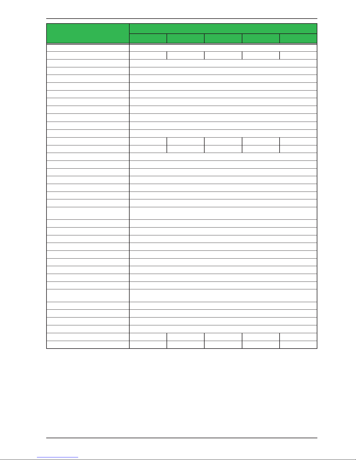
Page 25
Intepro Systems
www.inteproate.com
service@inteproate.com
PSI 9000 3U Series
10 kW / 15 kW
Model
PSI 91000-30 PSI 9080-510 PSI 9200-210 PSI 9360-120 PSI 9500-90
Internal resistance regulation
Adjustment range 0...1000 Ω 0...5 Ω 0...28 Ω 0...90 Ω 0...166 Ω
Accuracy
(1
≤2% of max. resistance ± 0.3% of rated current
Display: Resolution See section „1.9.6.4. Resolution of the displayed values“
Analog interface
(2
Set value inputs U, I, P, R
Actual value output U, I
Control signals DC on/o, remote control on/o, resistance mode on/o
Status signals CV, OVP, OT
Galvanic isolation to the device Max. 1500 V DC
Sample rate of inputs & outputs 500 Hz
Insulation Allowed oat (potential shift) on the DC output:
Negative terminal to PE Max. ±1500V DC ±400 V DC ±725 V DC ±725 V DC ±1500V DC
Positive terminal to PE Max. ±1800 V DC ±400 V DC ±1000 V DC ±1000 V DC ±1800 V DC
AC input <-> PE 2.5 kV DC
AC input <-> DC output 2.5 kV DC
Miscellaneous
Cooling Temperature controlled fans, front inlet, rear exhaust
Ambient temperature 0..50°C (32...122°F)
Storage temperature -20...70°C (-4...158°F)
Humidity < 80%, not condensing
Standards
IEC 61010:2010
EMC TÜV approved acc. IEC 61000-6-2:2005 and IEC 61000-6-3:2006 Class B
Overvoltage category 2
Protection class 1
Pollution degree 2
Operational altitude < 2000 m (1.242 mi)
Digital interfaces
Featured 1x USB-B for communication, 1x USB-A for functions, 1x GPIB (optional)
Slot (standard version) optional: CANopen, Probus, Pronet, RS232, CAN, Ethernet, ModBus TCP
Galvanic isolation from device Max. 1500 V DC
Terminals
Rear side
Share Bus, DC output, AC input, remote sensing, analog interface, USB-B, master-
slave bus, Interface module slot
Front side USB-A
Dimensions
Enclosure (WxHxD) 19“ x 3U x 682 mm (26.8”)
Total (WxHxD) 483 x 133 x 787 mm (19” x 5.2” x 31”)
Weight ~ 24 kg (52.9 lb) ~ 30 kg (66.1 lb) ~ 30 kg (66.1 lb) ~ 30 kg (66.1 lb) ~ 30 kg (66.1 lb)
Article number
(3
06238362 06238364 06238365 06238366 06238367
(1 Related to the nominal values, the accuracy denes the maximum deviation between an adjusted values and the true (actual) value
(2 For technical specications of the analog interface see „3.5.4.4 Analog interface specication“ on page 68
(3 Article number of the standard version, devices with options will have a dierent number

Page 26
Intepro Systems
www.inteproate.com
service@inteproate.com
PSI 9000 3U Series
15 kW
Model
PSI 9750-60 PSI 91000-40 PSI 91500-30
AC Input
Voltage (L-L) 208 V, ± 10%
Connection 3ph,PE 3ph,PE 3ph,PE
Frequency 45 - 65 Hz 45 - 65 Hz 45 - 65 Hz
Fusing (internal) 6x T32 A 6x T32 A 6x T32 A
Leak current < 3.5 mA < 3.5 mA < 3.5 mA
Power factor > 0.99 > 0.99 > 0.99
DC Output
Max. output voltage U
Max
750 V 1000 V 1500 V
Max. output current I
Max
60 A 40 A 30 A
Max. output power P
Max
15 kW 15 kW 15 kW
Overvoltage protection range 0...825 V 0...1100 V 0...1650 V
Overcurrent protection range 0...66 A 0...44 A 0...33 A
Overpower protection range 0…16.50 kW 0…16.50 kW 0…16.50 kW
Temperature coecient for set
values Δ/K
Voltage / current: 100 ppm
Output capacitance (approx.) 310 μF 133 μF 84 μF
Voltage regulation
Adjustment range 0...765 V 0...1020 V 0...1530 V
Accuracy
(1
(at 23 ± 5°C) < 0.1% U
Max
< 0.1% U
Max
< 0.1% U
Max
Line regulation at ±10% ΔU
AC
< 0.02% U
Max
< 0.02% U
Max
< 0.02% U
Max
Load regulation at 0...100% load < 0.05% U
Max
< 0.05% U
Max
< 0.05% U
Max
Rise time 10...90% ΔU Max. 30 ms Max. 30 ms Max. 30 ms
Transient time after load step < 1.5 ms < 1.5 ms < 1.5 ms
Display: Resolution See section „1.9.6.4. Resolution of the displayed values“
Display: Accuracy
(4
≤ 0.2% U
Max
≤ 0.2% U
Max
≤ 0.2% U
Max
Ripple
(2
< 800 mVPP
< 200 mV
RMS
< 2000 mVPP
< 300 mV
RMS
< 2400 mVPP
< 400 mV
RMS
Remote sensing compensation Max. 5% U
Max
Max. 5% U
Max
Max. 5% U
Max
Fall time at no load after switching
DC output o
Down from 100% to <60 V: less than 10 s
Current regulation
Adjustment range 0...61.2 A 0...40.8 A 0...30.6 A
Accuracy
(1
(at 23 ± 5°C) < 0.2% I
Max
< 0.2% I
Max
< 0.2% I
Max
Line regulation at ±10% ΔU
AC
< 0.05% I
Max
< 0.05% I
Max
< 0.05% I
Max
Load regulation at 0...100% ΔU
OUT
< 0.15% I
Max
< 0.15% I
Max
< 0.15% I
Max
Ripple
(2
< 48 mA
RMS
< 10 mA
RMS
< 26 mA
RMS
Display: Resolution See section „1.9.6.4. Resolution of the displayed values“
Display: Accuracy
(4
≤ 0.2% I
Max
≤ 0.2% I
Max
≤ 0.2% I
Max
Power regulation
Adjustment range 0…15.3 kW 0…15.3 kW 0…15.3 kW
Accuracy
(1
(at 23 ± 5°C) < 1% P
Max
< 1% P
Max
< 1% P
Max
Line regulation at ±10% ΔU
AC
< 0.05% P
Max
< 0.05% P
Max
< 0.05% P
Max
Load reg. at 10-90% ΔU
OUT
* ΔI
OUT
< 0.75% P
Max
< 0.75% P
Max
< 0.75% P
Max
Display: Resolution See section „1.9.6.4. Resolution of the displayed values“
Display: Accuracy
(4
≤ 0.85% P
Max
≤ 0.85% P
Max
≤ 0.85% P
Max
Eciency
(3
~ 94% ~ 94% ~ 95%
(1 Related to the nominal values, the accuracy denes the maximum deviation between an adjusted values and the true (actual) value.
Example: a 80 V model has min. 0.1% voltage accuracy, that is 80 mV. When adjusting the voltage to 5 V, the actual value is allowed to dier max. 80 mV, which
means it might be between 4.92 V and 5.08 V.
(2 RMS value: LF 0...300 kHz, PP value: HF 0...20MHz
(3 Typical value at 100% output voltage and 100% power
(4 The display error adds to the error of the related actual value on the DC output.
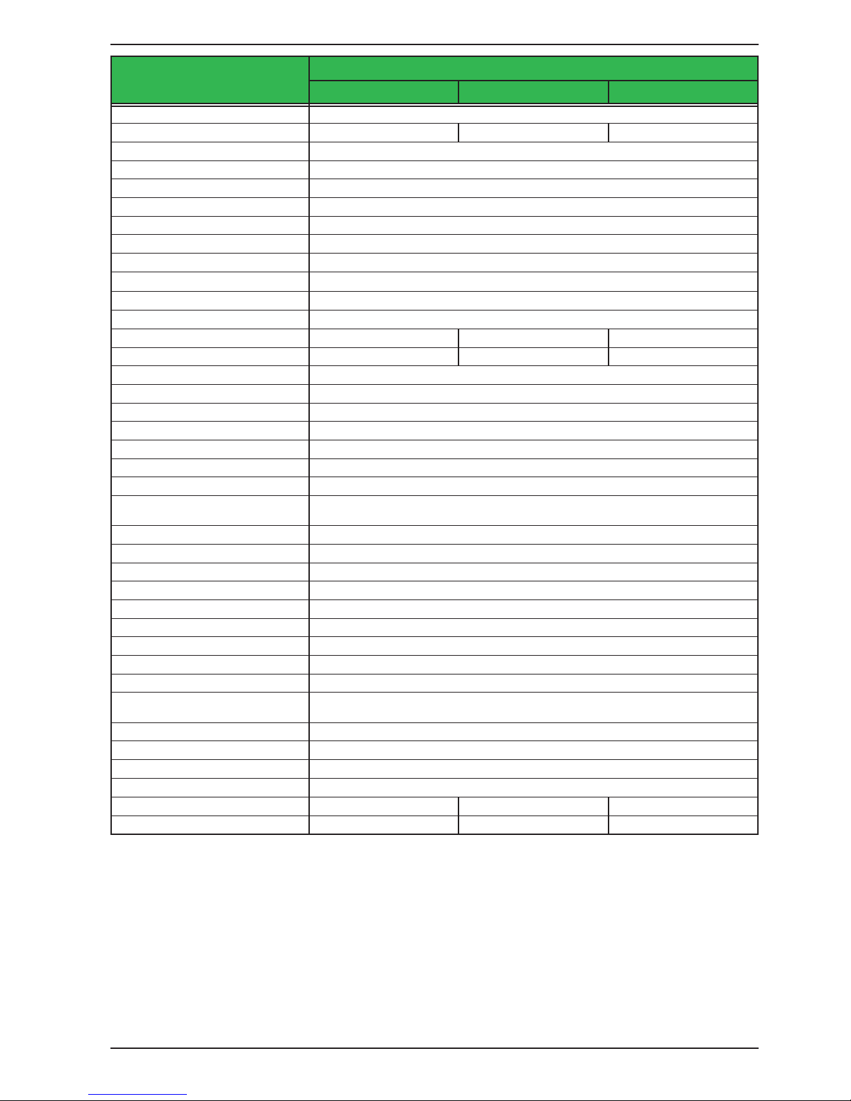
Page 27
Intepro Systems
www.inteproate.com
service@inteproate.com
PSI 9000 3U Series
15 kW
Model
PSI 9750-60 PSI 91000-40 PSI 91500-30
Internal resistance regulation
Adjustment range 0...375 Ω 0...810 Ω 0...1500 Ω
Accuracy
(1
≤2% of max. resistance ± 0.3% of rated current
Display: Resolution See section „1.9.6.4. Resolution of the displayed values“
Analog interface
(2
Set value inputs U, I, P, R
Actual value output U, I
Control signals DC on/o, remote control on/o, resistance mode on/o
Status signals CV, OVP, OT
Galvanic isolation to the device Max. 1500 V DC
Sample rate of inputs & outputs 500 Hz
Insulation Allowed oat (potential shift) on the DC output:
Negative terminal to PE Max. ±1500V DC ±1500V DC ±1500V DC
Positive terminal to PE Max. ±1800 V DC ±1800 V DC ±1800 V DC
AC input <-> PE 2.5 kV DC
AC input <-> DC output 2.5 kV DC
Miscellaneous
Cooling Temperature controlled fans, front inlet, rear exhaust
Ambient temperature 0..50°C (32...122°F)
Storage temperature -20...70°C (-4...158°F)
Humidity < 80%, not condensing
Standards
IEC 61010:2010
EMC TÜV approved acc. IEC 61000-6-2:2005 and IEC 61000-6-3:2006 Class B
Overvoltage category 2
Protection class 1
Pollution degree 2
Operational altitude < 2000 m (1.242 mi)
Digital interfaces
Featured 1x USB-B for communication, 1x USB-A for functions, 1x GPIB (optional)
Slot (standard version) optional: CANopen, Probus, Pronet, RS232, CAN, Ethernet, ModBus TCP
Galvanic isolation from device Max. 1500 V DC
Terminals
Rear side
Share Bus, DC output, AC input, remote sensing, analog interface, USB-B, master-
slave bus, Interface module slot
Front side USB-A
Dimensions
Enclosure (WxHxD) 19“ x 3U x 682 mm (26.8”)
Total (WxHxD) 483 x 133 x 787 mm (19” x 5.2” x 31”)
Weight ~ 30 kg (66.1 lb) ~ 30 kg (66.1 lb) ~ 30 kg (66.1 lb)
Article number
(3
06238368 06238370 06238369
(1 Related to the nominal values, the accuracy denes the maximum deviation between an adjusted values and the true (actual) value
(2 For technical specications of the analog interface see „3.5.4.4 Analog interface specication“ on page 68
(3 Article number of the standard version, devices with options will have a dierent number
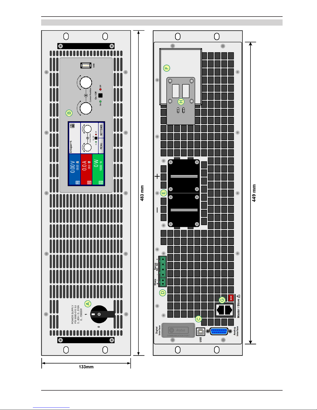
Page 28
Intepro Systems
www.inteproate.com
service@inteproate.com
PSI 9000 3U Series
A - Power switch D - Share Bus and remote sensing connection G - Master-Slave ports
B - Control panel E - DC output (view shows terminal type 1) H - Plug xture & strain relief
C - Control interfaces (digital, analog) F - AC input connection (EU model shown)
Figure 1 - Front view Figure 2 - Rear view (standard version)
1.8.5 Views
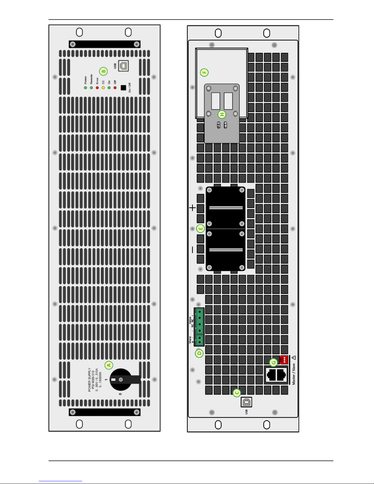
Page 29
Intepro Systems
www.inteproate.com
service@inteproate.com
PSI 9000 3U Series
Figure 3 - Front view (PSI 9000 Slave) Figure 4 - Rear view (PSI 9000 Slave)
A - Power switch D - Share Bus and remote sensing connection G - Master-Slave ports
B - Control panel E - DC output H - Plug xture & strain relief
C - USB interface F - AC input lter
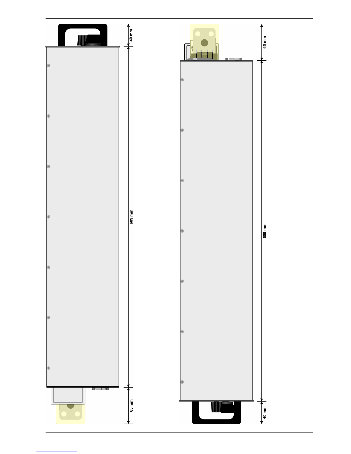
Page 30
Intepro Systems
www.inteproate.com
service@inteproate.com
PSI 9000 3U Series
Figure 5 - Side view (right)
Figure 6 - Side view (left)
 Loading...