

Intepro systems PS 9200-25 1U, PS 9500-10 1U, PS 9200-50 1U, PS 9080-100 1U, PS 9360-15 1U User Manual
...
PS 9000 1U Series
DC Laboratory Power Supply
THE POWER TEST EXPERTS
User Manual
Attention! This document is only valid for devices with
rmware “KE: 2.07” and “HMI: 2.03”, or higher. For
availability of updates for your device check our website
or contact us.
www.InteproATE.com Version 5 Dec 2016


3
PS 9000 1U Series
PS 9000 1U Series • DC Laboratory Power Supply • User Manual
TABLE OF CONTENTS
1
GENERAL
1.1 About this document ......................................5
1.1.1 Retention and use ..........................................5
1.1.2 Copyright ........................................................5
1.1.3 Validity ............................................................5
1.1.4 Explanation of symbols ..................................5
1.2 Warranty ......................................................... 5
1.3 Limitation of liability ........................................5
1.4 Disposal of equipment ...................................6
1.5 Product key ....................................................6
1.6 Intended usage ..............................................6
1.7 Safety ............................................................. 7
1.7.1 Safety notices .................................................7
1.7.2 Responsibility of the user...............................7
1.7.3 Responsibility of the operator .......................8
1.7.4 User requirements .........................................8
1.7.5 Alarm signals ..................................................9
1.8 Technical data ................................................9
1.8.1 Approved operating conditions ......................9
1.8.2 General technical data ...................................9
1.8.3 Specic technical data .................................10
1.8.4 Views ............................................................14
1.9 Construction and function ............................18
1.9.1 General description ......................................18
1.9.2 Block diagram ..............................................18
1.9.3 Scope of delivery .........................................18
1.9.4 The control panel (HMI) ...............................19
1.9.5 Sense connector (remote sensing) .............20
1.9.6 USB port .......................................................21
1.9.7 Ethernet port ................................................21
1.9.8 Analog interface ...........................................21
1.9.9 Share Bus-Connection ................................21
2
INSTALLATION & COMMISSIONING
2.1 Transport and storage .................................22
2.1.1 Transport ......................................................22
2.1.2 Packaging ....................................................22
2.1.3 Storage .........................................................22
2.2 Unpacking and visual check ........................22
2.3 Installation ....................................................22
2.3.1 Safety procedures before installation and
use ................................................................22
2.3.2 Preparation ...................................................22
2.3.3 Installing the device .....................................23
2.3.4 Connection to AC supply .............................23
2.3.5 Connection to DC loads ...............................24
2.3.6 Grounding of the DC output ........................25
2.3.7 Connection of remote sensing ....................25
2.3.8 Connecting the “Share” bus ........................25
2.3.9 Connecting the analog interface .................26
2.3.10 Connecting the USB port .............................26
2.3.11 Initial commission .........................................26
2.3.12 Initial network setup .....................................27
2.3.13 Commission after a rmware update or a
long period of non-use .................................27
3
OPERATION AND APPLICATION
3.1 Important notes ............................................28
3.1.1 Personal safety ............................................28
3.1.2 General .........................................................28
3.2 Operating modes .........................................28
3.2.1 Voltage regulation / Constant voltage .........28
3.2.2 Current regulation / constant current / current
limiting ..........................................................28
3.2.3 Power regulation / constant power / power
limiting ..........................................................29
3.3 Alarm conditions ..........................................30
3.3.1 Power Fail ...................................................30
3.3.2 Overtemperature ..........................................30
3.3.3 Overvoltage ..................................................30
3.3.4 Overcurrent ..................................................30
3.3.5 Overpower ....................................................30
3.4 Manual operation .........................................31
3.4.1 Switching on the device ...............................31
3.4.2 Switching off the device ...............................31
3.4.3 Conguration in the setup menu .................31
3.4.4 Adjustment limits ..........................................35
3.4.5 Display modes for actual and set values ....36
3.4.6 Manual adjustment of set values .................36
3.4.7 The quick menu ...........................................37
3.4.8 Switching the DC output on or off ................37
3.5 Remote control .............................................38
3.5.1 General .........................................................38
3.5.2 Control locations ..........................................38
3.5.3 Remote control via a digital interface ..........38
3.5.4 Remote control via the analog interface
(AI) ................................................................39
3.6 Alarms and monitoring .................................43
3.6.1 Denition of terms ........................................43
3.6.2 Device alarm handling .................................43
3.7 Control panel (HMI) lock ..............................44
3.8 Loading and saving a user prole ...............45
3.9 Other applications ........................................46
3.9.1 Parallel operation in Share Bus mode ........46
3.9.2 Series connection ........................................47
3.9.3 Operation as battery charger .......................47
3.9.4 Two quadrants operation (2QO)..................48
4. SERVICE AND MAINTENANCE
4.1 Maintenance / cleaning................................50
4.2 Fault nding / diagnosis / repair...................50
4.2.1 Replacing a defect mains fuse.....................50
4.2.2 Firmware updates ........................................50
4.3.1 Update of control panel (HMI) .....................50
4.3.2 Update of communication unit (KE) ............50

4
PS 9000 1U Series
© 2015 Intepro Systems, LP. Specications subject to change without notice.
4.3 Calibration (readjustment) ...........................51
4.3.1 Preface .........................................................51
4.3.1.1 Preparation ...................................................51
4.3.2 Calibration procedure ..................................51
5
CONTACT AND SUPPORT
5.1 General .........................................................53
5.2 Contact Options ...........................................53
5
PS 9000 1U Series
PS 9000 1U Series • DC Laboratory Power Supply • User Manual
1. General
1.1 About this document
1.1.1 Retention and use
This document is to be kept near the equipment for future reference and explanation of the operation of the device.
This document is to be delivered and kept with the equipment in case of change of location and/or user.
1.1.2 Copyright
All information in this manual is copyrighted by Intepro Systems. Reprinting or copying in whole or part, and use
of this manual for other purposes is forbidden and breach may lead to legal process.
1.1.3 Validity
This manual is valid for the following equipment including derived variants.
Model Article nr. Model Article nr.
PS 9080-50 1U 06230400 PS 9080-100 1U 06230405
PS 9200-25 1U 06230401 PS 9200-50 1U 06230406
PS 9360-15 1U 06230402 PS 9360-30 1U 06230407
PS 9500-10 1U 06230403 PS 9500-20 1U 06230408
PS 9750-06 1U 06230404 PS 9750-12 1U 06230409
Changes and modications for special models will be listed in a separate document.
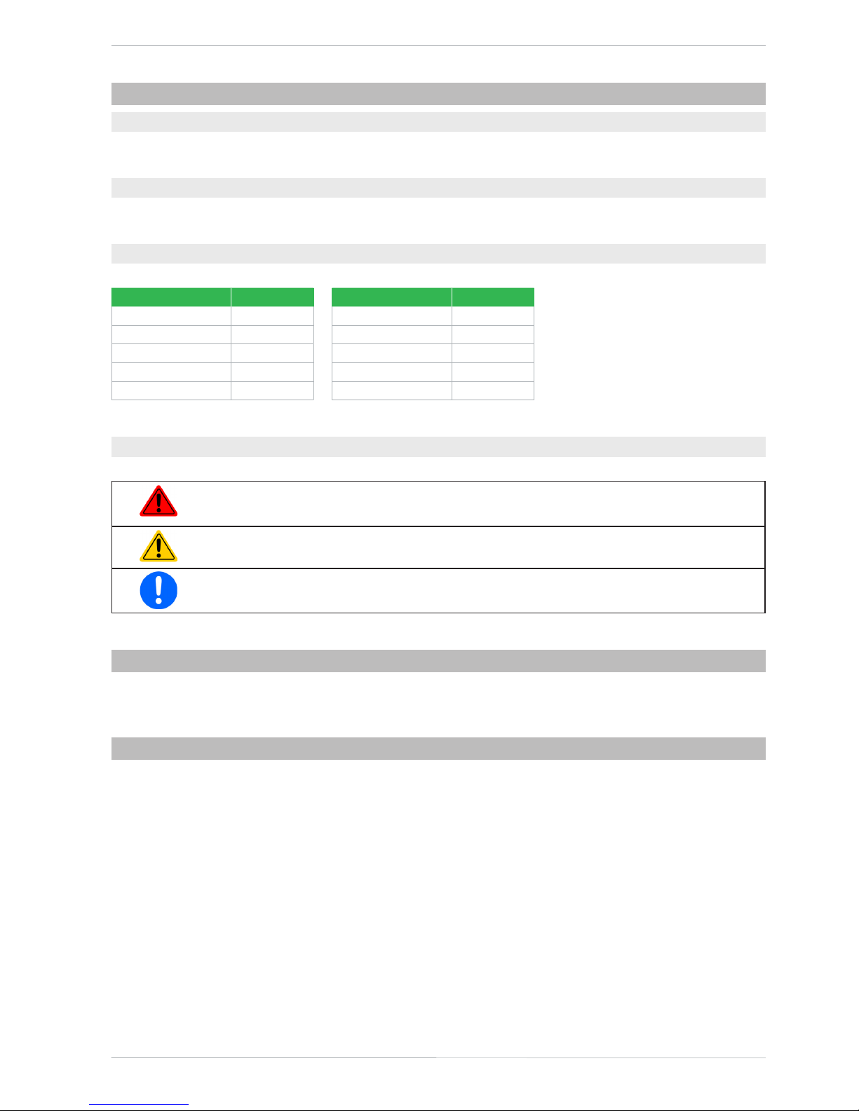
1.1.4 Explanation of symbols
Warning and safety notices as well as general notices in this document are shown in a box with a symbol as follows:
Symbol for a life threatening danger
Symbol for general safety notices (instructions and damage protection bans) or important infor-
mation for operation
Symbol for general notices
1.2 Warranty
Intepro Systems guarantees the functional competence of the applied technology and the stated performance
parameters. The warranty period begins with the delivery of free from defects equipment.
Terms of guarantee are included in the general terms and conditions of Intepro Systems.
1.3 Limitation of liability
All statements and instructions in this manual are based on current norms and regulations, up-to-date technology
and our long term knowledge and experience. Intepro Systems accepts no liability for losses because of:
• Use for purposes other than dened
• Use by untrained personnel
• Rebuilding by the customer
• Technical changes
• Use of non-authorized spare parts
The actual delivered device(s) may differ from the explanations and diagrams given here because of the latest
technical changes or customized models that include additional ordered options.
6
PS 9000 1U Series
© 2015 Intepro Systems, LP. Specications subject to change without notice.
1.4 Disposal of equipment
Any equipment intended for disposal must, according to applicable laws and regulations, be returned to Intepro
Systems for scrapping, unless the person operating the piece of equipment or another, delegated person is conducting the disposal. Our equipment falls under these regulations and is accordingly marked with the following symbol:
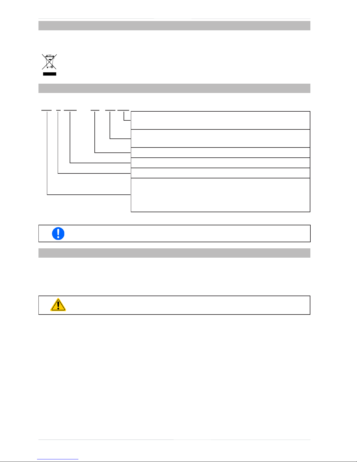
1.5 Product key
Decoding of the product description on the label, using an example:
PS 9 080 - 50 1U zzz
Field for identication of installed options and/or special models
S01...S0x = Special models
Construction (not always given)
1U / 2U / 3U = 19" frame with 1 U, 2 U or 3 U
Maximum current of the device in Ampere
Maximum voltage of the device in Volt
Series : 8 = Series 8000 or 800, 9 = Series 9000
Type identication:
PS = Power Supply, usually programmable
PSI = Power Supply Intelligent, always programmable
ELR = Electronic Load with Recovery
Special models are always derived from standard models and can vary in output voltage and
current from those given.
1.6 Intended usage
The equipment is intended to be used, if a power supply or battery charger, only as a variable voltage and current
source, or, if an electronic load, only as a variable current sink.
Typical application for a power supply is DC supply to any relevant user, for a battery charger the charging of various battery types and for electronic loads the replacement of Ohm resistance by an adjustable DC current sink in
order to load relevant voltage and current sources of any type.
• Claims of any sort due to damage caused by unintended use will not be accepted.
• All damage caused by unintended use is solely the responsibility of the operator.
7
PS 9000 1U Series
PS 9000 1U Series • DC Laboratory Power Supply • User Manual
1.7 Safety
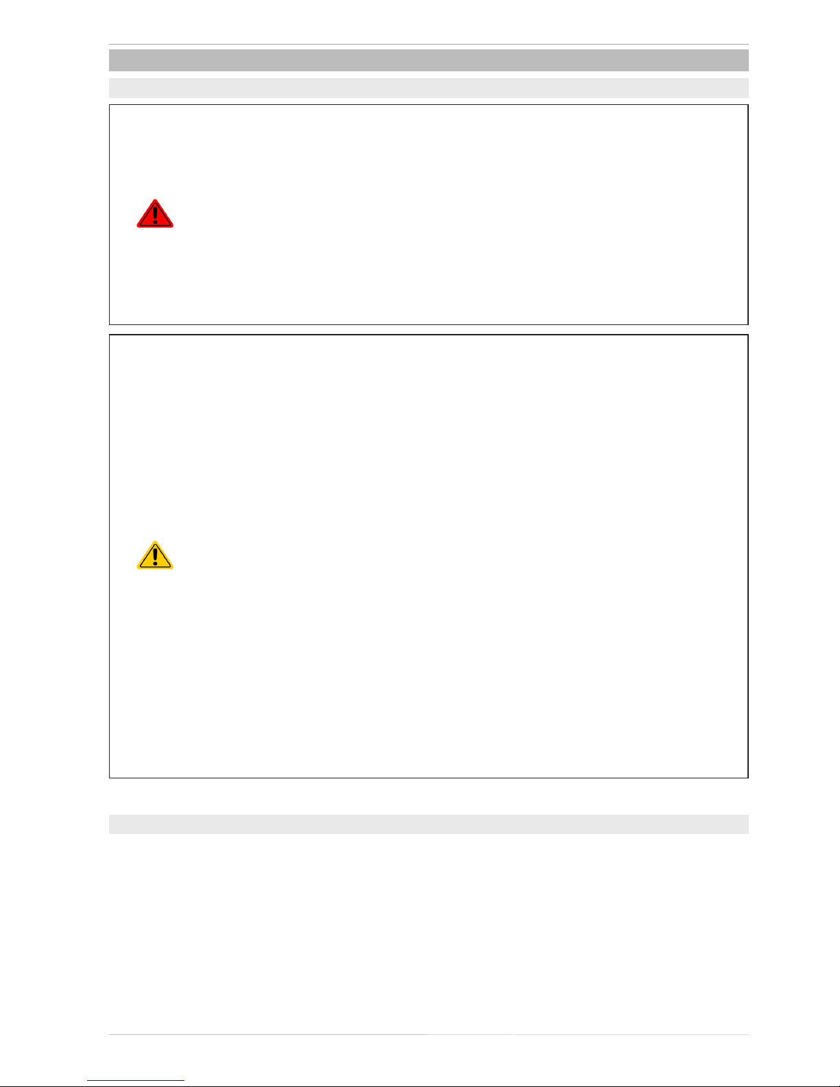
1.7.1 Safety notices
Mortal danger - Hazardous voltage
• Electrical equipment operation means that some parts will involve dangerous voltage.
Therefore all parts under voltage must be covered!
• All work on connections must be carried out under zero voltage (output not connected
to load) and may only be performed by qualied and informed persons. Improper actions can cause fatal injury as well as serious material damage!
• Never touch cables or connectors directly after unplugging from mains supply as the
danger of electric shock remains!
• Never touch the contacts on DC output terminal directly after switching off the DC
output, because there still can dangerous voltage present, sinking more or less slowly
depending on the load! There can be dangerous potential between negative DC output
to PE or positive DC output to PE because of charged X capacitors.
• The equipment must only be used as intended
• The equipment is only approved for use within the connection limits stated on the product label.
• Do not insert any object, particularly metallic, through the ventilator slots
• Avoid any use of liquids near the equipment. Protect the device from wet, damp and conden-
sation.
• For power supplies and battery chargers: do not connect users, particularly low resistance, to
devices under power; sparking may occur which can cause burns as well as damage to the
equipment and to the user.
• For electronic loads: do not connect power sources to equipment under power, sparking may
occur which can cause burns as well as damage to the equipment and to the source.
• ESD regulations must be applied when plugging interface cards or modules into the relative slot
• Interface cards or modules may only be attached or removed after the device is switched off.
It is not necessary to open the device.
• Do not connect external power sources with reversed polarity to DC input or outputs! The
equipment will be damaged.
• For power supply devices: avoid where possible connecting external power sources to the DC
output, and never those that can generate a higher voltage than the nominal voltage of the device.
• For electronic loads: do not connect a power source to the DC input which can generate a volt-
age more than 120% of the nominal input voltage of the load. The equipment is not protected
against over voltage and may be irreparably damaged.
• Never insert a network cable which is connected to Ethernet or its components into the master-
slave socket on the back side of the device!
• Always congure the various protecting features against overvoltage, overpower, etc. for sensi-
tive loads to what the currently-used application requires
1.7.2 Responsibility of the user
The equipment is an industrial application and as such is governed by all legal safety regulations. In addition to the
warning and safety notices in this manual all relevant safety, accident prevention and environmental regulations
shall also apply. The users of the equipment shall:
• be informed of the relevant job safety requirements
• work to the dened responsibilities for operation, maintenance and cleaning of the equipment
• have read and understood the operating manual before starting work
• use the designated and recommended safety equipment.
Additionally, anyone working with the equipment is responsible for ensuring that the device is at all times technically t for use.

8
PS 9000 1U Series
© 2015 Intepro Systems, LP. Specications subject to change without notice.
1.7.3 Responsibility of the operator
The operator is any natural or legal person who uses the equipment or delegates the usage to a third party, and
is responsible during its usage for the safety of the user, other personnel or third parties.
The equipment is an industrial application and as such is governed by all legal safety regulations. In addition to the
warning and safety notices in this manual all relevant safety, accident prevention and environmental regulations
shall also apply. In particular the operator shall:
• be acquainted with the relevant job safety requirements
• identify other possible dangers arising from the specic usage conditions at the work station via a risk assessment
• introduce the necessary steps in the operating procedures for the local conditions
• regularly control that the operating procedures are current
• update the operating procedures where necessary to reect changes in regulation, standards or operating con-
ditions.
• dene clearly and unambiguously the responsibilities for operation, maintenance and cleaning of the equipment.
• ensure that all employees who use the equipment have read and understood the manual. Furthermore the users
are to be regularly schooled in working with the equipment and the possible dangers.
• provide all personnel who work with the equipment with the designated and recommended safety equipment
Furthermore, the operator is responsible for ensuring that the device is at all times technically t for use.
1.7.4 User requirements
Any activity with equipment of this type may only be performed by persons who are able to work correctly and
reliably and satisfy the requirements of the job.
• Persons whose reaction capability is negatively inuenced by e.g. drugs, alcohol or medication may not operate
the equipment.
• Age or job-related regulations valid at the operating site must always be applied.
Danger for unqualied users
Improper operation can cause person or object damage. Only persons who have the necessary
training, knowledge and experience may use the equipment.
Delegated persons are those who have been properly and demonstrably instructed in their tasks and the atten-
dant dangers.
Qualied persons are those who are able through training, knowledge and experience as well as knowledge of
the specic details to carry out all the required tasks, identify dangers and avoid personal and other risks.

9
PS 9000 1U Series
PS 9000 1U Series • DC Laboratory Power Supply • User Manual
1.7.5 Alarm signals
The equipment offers various possibilities for signalling alarm conditions, however, not for danger situations. The
signals may be optical (on the display as text) acoustic (piezo buzzer) or electronic (pin/status output of an analog
interface). All alarms will cause the device to permanently or temporarily switch off the DC output.
The meaning of the signals is as follows:
Signal OT
(OverTemperature)
• Overheating of the device
• DC output will be switched off temporarily
• Non-critical
Signal OVP
(OverVoltage)
• Overvoltage shutdown of the DC output due to high voltage entering the device or gen-
erated by the device itself due to a defect or because the adjusted OVP threshold was
lower than the actual output voltage
• Critical! The device and/or the load could be damaged
Signal OCP
(OverCurrent)
• Shutdown of the DC output due to excess of the preset limit
• Non-critical, protects the load from excessive current consumption
Signal OPP
(OverPower)
• Shutdown of the DC output due to excess of the preset limit
• Non-critical, protects the load from excessive power consumption
Signal PF
(Power Fail)
• DC output shutdown due to AC undervoltage or defect of the AC input circuit
• Critical on overvoltage! AC input circuit could be damaged
1.8 Technical data
1.8.1 Approved operating conditions
• Use only inside dry buildings
• Ambient temperature 0-50°C
• Operational altitude: max. 2000 m above sea level
• Max 80% RH up to 30°C, linear decrease to 50% RH at 50°C
1.8.2 General technical data
Display: Dot matrix, 240pt x 64pt
Controls: 2 rotary knobs with button function, 6 pushbuttons
The nominal values for the device determine the maximum adjustable ranges.

10
PS 9000 1U Series
© 2015 Intepro Systems, LP. Specications subject to change without notice.
1.8.3 Specic technical data
1500 W
Model 1U
PS 9080-50 PS 9200-25 PS 9360-15 PS 9500-10 PS 9750-06
AC Input
Input voltage (w/o derating) 150...264 V AC 150...264 V AC 150...264 V AC 150...264 V AC 150...264 V AC
Input voltage (w/ derating)
1000 W
100...150 VAC
1000 W
100...150 VAC
1000 W
100...150 VAC
1000 W
100...150 VAC
1000 W
100...150 VAC
Input connection 1ph,N,PE 1ph,N,PE 1ph,N,PE 1ph,N,PE 1ph,N,PE
Input frequency 50/60 Hz 50/60 Hz 50/60 Hz 50/60 Hz 50/60 Hz
Input fuse (internal) T16 A T16 A T16 A T16 A T16 A
Leak current < 3.5 mA < 3.5 mA < 3.5 mA < 3.5 mA < 3.5 mA
Power factor ~ 0.99 ~ 0.99 ~ 0.99 ~ 0.99 ~ 0.99
Idle mode power consumption ~ 70 W ~ 70 W ~ 70 W ~ 70 W ~ 70 W
DC Output
Max. output voltage U
Max
80 V 200 V 360 V 500 V 750 V
Max. output current I
Max
50 A 25 A 15 A 10 A 6 A
Max. output power P
Max
1500 W 1500 W 1500 W 1500 W 1500 W
Overvoltage protection range 0...88 V 0...220 V 0...396 V 0...550 V 0...825 V
Overcurrent protection range 0...55 A 0...27,5 A 0...17,6 A 0...11 A 0...6,6 A
Overpower protection range 0…1650 W 0…1650 W 0…1650 W 0…1650 W 0…1650 W
Temperature coefcient Voltage / current: 100 ppm/K
Output capacitance (approx.)
5640 μF 1000 μF 470 μF 105 μF 49 μF
Voltage regulation
Adjustment range 0...81.6 V 0...204 V 0...367.2 V 0...510 V 0...765 V
Accuracy
(1
(at 23 ± 5°C) < 0.1% U
Nenn
< 0.1% U
Nenn
< 0.1% U
Nenn
< 0.1% U
Nenn
< 0.1% U
Nenn
Line regulation at ±10% ΔU
AC
< 0.02% U
Nenn
< 0.02% U
Nenn
< 0.02% U
Nenn
< 0.02% U
Nenn
< 0.02% U
Nenn
Load regulation at 0...100% load < 0.05% U
Nenn
< 0.05% U
Nenn
< 0.05% U
Nenn
< 0.05% U
Nenn
< 0.05% U
Nenn
Rise time 10...90% ΔU Max. 15 ms Max. 15 ms Max. 15 ms Max. 15 ms Max. 15 ms
Transient time after load step < 1.7 ms < 1.4 ms < 2.2 ms < 2 ms < 2 ms
Display: Resolution See section “1.9.4.4. Resolution of the displayed values”
Display: Accuracy
(3
≤ 0.2% U
Nom
≤ 0.2% U
Nom
≤ 0.2% U
Nom
≤ 0.2% U
Nom
≤ 0.2% U
Nom
Ripple
(2
< 100 mVPP
< 5.2 mV
RMS
< 293 mVPP
< 51 mV
RMS
< 195 mVPP
< 33 mV
RMS
< 293 mVPP
< 63 mV
RMS
< 260 mVPP
< 40 mV
RMS
Remote sensing compensation Max. 5% U
Nenn
Max. 5% U
Nenn
Max. 5% U
Nenn
Max. 5% U
Nenn
Max. 5% U
Nenn
Fall time (at no load) after
switching DC output off
Down from 100% to <60 V: less than 10 s
Current regulation
Adjustment range 0...51 A 0...25.5 A 0...15.3 A 0...10.2 A 0...6.12 A
Accuracy
(1
(at 23 ± 5°C) < 0.2% I
Nom
< 0.2% I
Nom
< 0.2% I
Nom
< 0.2% I
Nom
< 0.2% I
Nom
Line regulation at ±10% ΔU
AC
< 0.05% I
Nom
< 0.05% I
Nom
< 0.05% I
Nom
< 0.05% I
Nom
< 0.05% I
Nom
Load regulation at 0...100% ΔU
OUT
< 0.15% I
Nom
< 0.15% I
Nom
< 0.15% I
Nom
< 0.15% I
Nom
< 0.15% I
Nom
Ripple
(2
< 75 mA
PP
< 29 mA
PP
< 10 mA
PP
< 9.2 mA
PP
< 4.1 mA
PP
Display: Resolution See section “1.9.4.4. Resolution of the displayed values”
Display: Accuracy
(3
≤ 0.2% I
Nom
≤ 0.2% I
Nom
≤ 0.2% I
Nom
≤ 0.2% I
Nom
≤ 0.2% I
Nom
Power regulation
Adjustment range 0…1530 W 0…1530 W 0…1530 W 0…1530 W 0…1530 W
Accuracy
(1
(at 23 ± 5°C) < 1% P
Nom
< 1% P
Nom
< 1% P
Nom
< 1% P
Nom
< 1% P
Nom
Line regulation at ±10% ΔU
AC
< 0.05% P
Nom
< 0.05% P
Nom
< 0.05% P
Nom
< 0.05% P
Nom
< 0.05% P
Nom
Load regulation at 10-90% ΔU*ΔI < 0.75% P
Nom
< 0.75% P
Nom
< 0.75% P
Nom
< 0.75% P
Nom
< 0.75% P
Nom
Display: Resolution See section “1.9.4.4. Resolution of the displayed values”
Efciency at 100% U
DC
~ 91% ~ 93% ~ 94% ~ 94% ~ 95%
Efciency at 100% I
DC
~ 89% ~ 90% ~ 92% ~ 92% ~ 94%
(1 Related to the nominal values, the accuracy denes the maximum deviation between an adjusted values and the true (actual) value.
Example: a 80 V model has min. 0.1% voltage accuracy, that is 80 mV. When adjusting the voltage to 5 V, the actual value is allowed to differ max. 80 mV, which
means it might be between 4.92 V and 5.08 V.
(2 RMS value: LF 0...300 kHz, PP value: HF 0...20MHz
(3 The display error adds to the error of the related actual value on the DC output

11
PS 9000 1U Series
PS 9000 1U Series • DC Laboratory Power Supply • User Manual
1500 W
Model 1U
PS 9080-50 PS 9200-25 PS 9360-15 PS 9500-10 PS 9750-06
Analog interface
(1
Type Sub-D, 15 pole, female
Set value inputs U, I, P U, I, P U, I, P U, I, P U, I, P
Actual value output U, I U, I U, I U, I U, I
Control signals
DC on/off,
Remote on/off
DC on/off,
Remote on/off
DC on/off,
Remote on/off
DC on/off,
Remote on/off
DC on/off,
Remote on/off
Status signals CV, OVP, OT CV, OVP, OT CV, OVP, OT CV, OVP, OT CV, OVP, OT
Galvanic isolation to the device Max. 1500 V DC Max. 1500 V DC Max. 1500 V DC Max. 1500 V DC Max. 1500 V DC
Insulation Allowed oat (potential shift) on the DC output:
Negative terminal to PE Max. ±400 V DC ±400 V DC ±400 V DC ±400 V DC ±400 V DC
Positive terminal to PE Max. +480 V DC +600 V DC +760 V DC +900 V DC +1150 V DC
Miscellaneous
Cooling Temperature controlled fans, front inlet, rear exhaust
Ambient temperature 0..50°C
Storage temperature -20...70°C
Humidity < 80%, not condensing
Standards EN 61010, EN 61326
Overvoltage category 2
Protection class 1
Pollution degree 2
Operational altitude < 2000 m
Digital interfaces
Featured 1x USB-B, 1x Ethernet
Galvanic isolation from device Max. 1500 V DC
USB specication USB 2.0, socket type B, VCOM driver
USB response time SCPI: max. 5 ms, ModBus: max. 5 ms
Ethernet specication RJ45, 10/100Mbit, TCP/IP, ICMP, HTTP, DHCP
Ethernet response time SCPI: max. 7 ms, ModBus: 9-17 ms
Terminals
Rear side Share Bus, DC output, AC input, remote sensing, analog interface, USB-B, Ethernet
Dimensions
Enclosure (WxHxD) 19” x 1U x 463 mm
Total (WxHxD) 483 x 44 x min. 565 mm
Weight ~ 10.5 kg ~ 10.5 kg ~ 10.5 kg ~ 10.5 kg ~ 10.5 kg
Article number 06230400 06230401 06230402 06230403 06230404
(1 For technical specications of the analog interface see “3.5.4.3 Analog interface specication” on page 40

12
PS 9000 1U Series
© 2015 Intepro Systems, LP. Specications subject to change without notice.
3000 W
Model 1U
PS 9080-100 PS 9200-50 PS 9360-30 PS 9500-20 PS 9750-12
AC Input
Input voltage (w/o derating) 207...264 V AC 207...264 V AC 207...264 V AC 207...264 V AC 207...264 V AC
Input voltage (w/ derating)
2500 W
180..207 VAC
2500 W
180..207 VAC
2500 W
180..207 VAC
2500 W
180..207 VAC
2500 W
180..207 VAC
Input connection 1ph,N,PE 1ph,N,PE 1ph,N,PE 1ph,N,PE 1ph,N,PE
Input frequency (w/ derating) 45...66 Hz 45...66 Hz 45...66 Hz 45...66 Hz 45...66 Hz
Input fuse (internal) T16 A T16 A T16 A T16 A T16 A
Leak current < 3.5 mA < 3.5 mA < 3.5 mA < 3.5 mA < 3.5 mA
Power factor ~ 0.99 ~ 0.99 ~ 0.99 ~ 0.99 ~ 0.99
Idle mode power consumption ~ 70 W ~ 70 W ~ 70 W ~ 70 W ~ 70 W
DC Output
Max. output voltage U
Max
80 V 200 V 360 V 500 V 750 V
Max. output current I
Max
100 A 50 A 30 A 20 A 12 A
Max. output power P
Max
3000 W 3000 W 3000 W 3000 W 3000 W
Overvoltage protection range 0...88 V 0...220 V 0...396 V 0...550 V 0...825 V
Overcurrent protection range 0...110 A 0...55 A 0...33 A 0...22 A 0...13,2 A
Overpower protection range 0…3300 W 0…3300 W 0…3300 W 0…3300 W 0…3300 W
Temperature coefcient Voltage / current: 100 ppm/K
Output capacitance (approx.) 8930 μF 1500 μF 705 μF 150 μF 70 μF
Voltage regulation
Adjustment range 0...81.6 V 0...204 V 0...367.2 V 0...510 V 0...765 V
Accuracy
(1
(at 23 ± 5°C) < 0.1% U
Nenn
< 0.1% U
Nenn
< 0.1% U
Nenn
< 0.1% U
Nenn
< 0.1% U
Nenn
Line regulation at ±10% ΔU
AC
< 0.02% U
Nenn
< 0.02% U
Nenn
< 0.02% U
Nenn
< 0.02% U
Nenn
< 0.02% U
Nenn
Load regulation at 0...100% load < 0.05% U
Nenn
< 0.05% U
Nenn
< 0.05% U
Nenn
< 0.05% U
Nenn
< 0.05% U
Nenn
Rise time 10...90% ΔU Max. 15 ms Max. 15 ms Max. 15 ms Max. 15 ms Max. 15 ms
Transient time after load step < 1.7 ms < 1.4 ms < 2.2 ms < 2 ms < 2 ms
Display: Resolution See section “1.9.4.4. Resolution of the displayed values”
Display: Accuracy
(3
≤ 0.2% U
Nom
≤ 0.2% U
Nom
≤ 0.2% U
Nom
Ripple
(2
< 76 mVPP
< 4.2 mV
RMS
< 234 mVPP
< 40 mV
RMS
< 156 mVPP
< 26 mV
RMS
< 234 mVPP
< 50 mV
RMS
< 260 mVPP
< 40 mV
RMS
Remote sensing compensation Max. 5% U
Nom
Max. 5% U
Nom
Max. 5% U
Nom
Max. 5% U
Nom
Max. 5% U
Nom
Fall time (at no load) after
switching DC output off
Down from 100% to <60 V: less than 10 s
Current regulation
Adjustment range 0...102 A 0...51 A 0...30.6 A 0...20.4 A 0...12.24 A
Accuracy
(1
(at 23 ± 5°C) < 0.2% I
Nenn
< 0.2% I
Nenn
< 0.2% I
Nenn
< 0.2% I
Nenn
< 0.2% I
Nenn
Line regulation at ±10% ΔU
AC
< 0.05% I
Nenn
< 0.05% I
Nenn
< 0.05% I
Nenn
< 0.05% I
Nenn
< 0.05% I
Nenn
Load regulation at 0...100% ΔU
OUT
< 0.15% I
Nenn
< 0.15% I
Nenn
< 0.15% I
Nenn
< 0.15% I
Nenn
< 0.15% I
Nenn
Ripple
(2
< 114 mA
PP
< 29 mA
PP
< 10 mA
PP
< 9.2 mA
PP
< 4.1 mA
PP
Display: Resolution See section “1.9.4.4. Resolution of the displayed values”
Display: Accuracy
(3
≤ 0.2% I
Nom
≤ 0.2% I
Nom
≤ 0.2% I
Nom
≤ 0.2% I
Nom
≤ 0.2% I
Nom
Power regulation
Adjustment range 0...3060 W 0...3060 W 0...3060 W 0...3060 W 0...3060 W
Accuracy
(1
(at 23 ± 5°C) < 1% P
Nenn
< 1% P
Nenn
< 1% P
Nenn
< 1% P
Nenn
< 1% P
Nenn
Line regulation at ±10% ΔU
AC
< 0.05% P
Nenn
< 0.05% P
Nenn
< 0.05% P
Nenn
< 0.05% P
Nenn
< 0.05% P
Nenn
Load regulation at 10-90% ΔU*ΔI < 0.75% P
Nenn
< 0.75% P
Nenn
< 0.75% P
Nenn
< 0.75% P
Nenn
< 0.75% P
Nenn
Display: Resolution See section “1.9.4.4. Resolution of the displayed values”
Efciency at 100% U
DC
~ 91% ~ 93% ~ 94% ~ 94% ~ 95%
Efciency at 100% I
DC
~ 89% ~ 90% ~ 92% ~ 92% ~ 94%
(1 Related to the nominal values, the accuracy denes the maximum deviation between an adjusted values and the true (actual) value.
Example: a 80 V model has min. 0.1% voltage accuracy, that is 80 mV. When adjusting the voltage to 5 V, the actual value is allowed to differ max. 80 mV, which
means it might be between 4.92 V and 5.08 V.
(2 RMS value: LF 0...300 kHz, PP value: HF 0...20MHz
(3 The display error adds to the error of the related actual value on the DC output

13
PS 9000 1U Series
PS 9000 1U Series • DC Laboratory Power Supply • User Manual
3000 W
Model 1U
PS 9080-100 PS 9200-50 PS 9360-30 PS 9500-20 PS 9750-12
Analog interface
(1
Type Sub-D, 15 pole, female
Set value inputs U, I, P U, I, P U, I, P U, I, P U, I, P
Actual value output U, I U, I U, I U, I U, I
Control signals
DC on/off,
Remote on/off
DC on/off,
Remote on/off
DC on/off,
Remote on/off
DC on/off,
Remote on/off
DC on/off,
Remote on/off
Status signals CV, OVP, OT CV, OVP, OT CV, OVP, OT CV, OVP, OT CV, OVP, OT
Galvanic isolation to the device Max. 1500 V DC Max. 1500 V DC Max. 1500 V DC Max. 1500 V DC Max. 1500 V DC
Insulation Allowed oat (potential shift) on the DC output:
Negative terminal to PE Max. ±400 V DC ±400 V DC ±400 V DC ±400 V DC ±400 V DC
Positive terminal to PE Max. +480 V DC +600 V DC +760 V DC +900 V DC +1150 V DC
Miscellaneous
Cooling Temperature controlled fans, front inlet, rear exhaust
Ambient temperature 0..50°C
Storage temperature -20...70°C
Humidity < 80%, not condensing
Standards EN 61010, EN 61326
Overvoltage category 2
Protection class 1
Pollution degree 2
Operational altitude < 2000 m
Digital interfaces
Featured 1x USB-B, 1x Ethernet
Galvanic isolation from device Max. 1500 V DC
USB specication USB 2.0, socket type B, VCOM driver
USB response time SCPI: max. 5 ms, ModBus: max. 5 ms
Ethernet specication RJ45, 10/100Mbit, TCP/IP, ICMP, HTTP, DHCP
Ethernet response time SCPI: max. 7 ms, ModBus: 9-17 ms
Terminals
Rear side Share Bus, DC output, AC input, remote sensing, analog interface, USB-B, Ethernet
Dimensions
Enclosure (WxHxD) 19” x 1U x 463 mm
Total (WxHxD) 483 x 44 x min. 565 mm
Weight ~ 11 kg ~ 11 kg ~ 11 kg ~ 11 kg ~ 11 kg
Article number 06230405 06230406 06230407 06230408 06230409
(1 For technical specications of the analog interface see “3.5.4.3 Analog interface specication” on page 40
14
PS 9000 1U Series
© 2015 Intepro Systems, LP. Specications subject to change without notice.
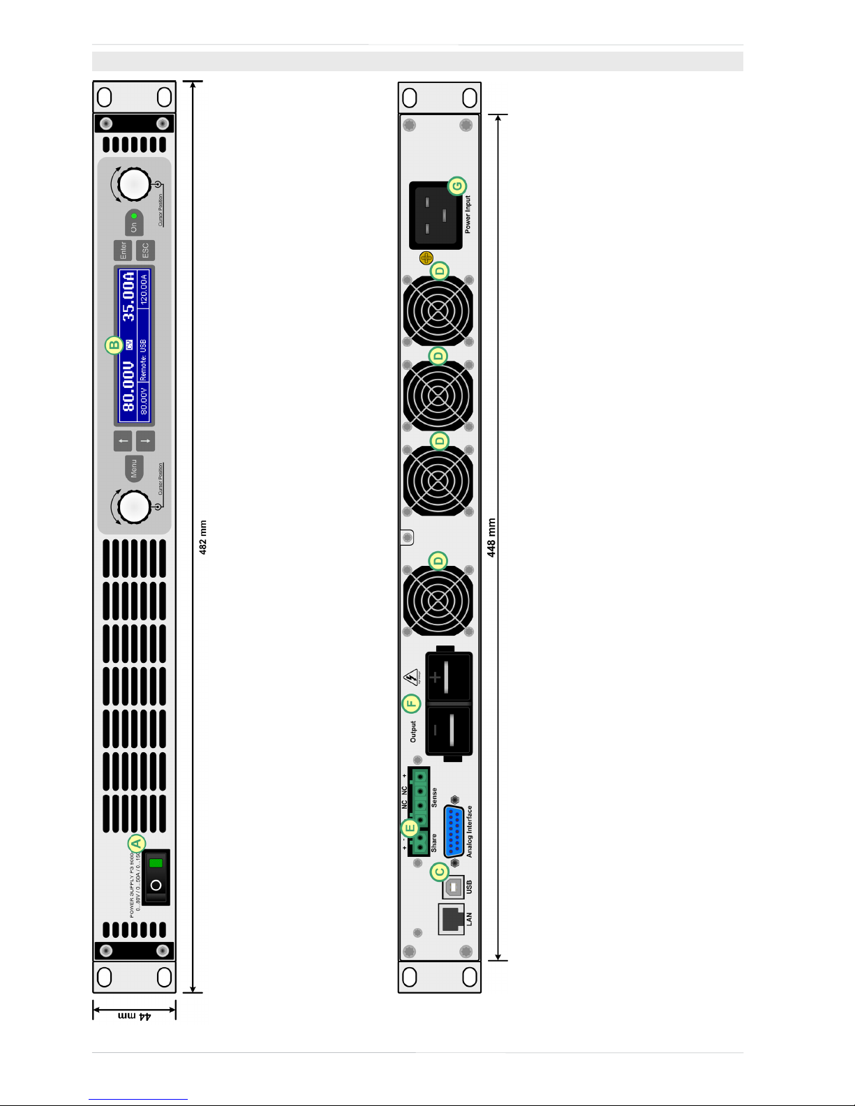
Figure 1 - Front side
Figure 2 - Rear side
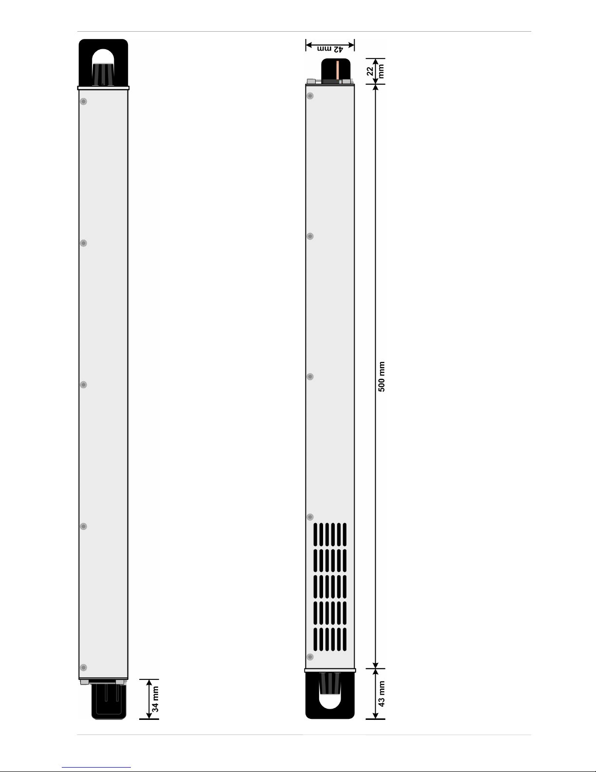
1.8.4 Views
A - Mains switch D - Exhausts G - AC input connector
B - Control panel E - Share Bus and remote sensing connectors
C - Control interfaces (digital, analog) F - DC output
15
PS 9000 1U Series
PS 9000 1U Series • DC Laboratory Power Supply • User Manual
Figure 3 - Left hand side view with DC cover
Figure 4 - Right hand side view without DC cover
16
PS 9000 1U Series
© 2015 Intepro Systems, LP. Specications subject to change without notice.
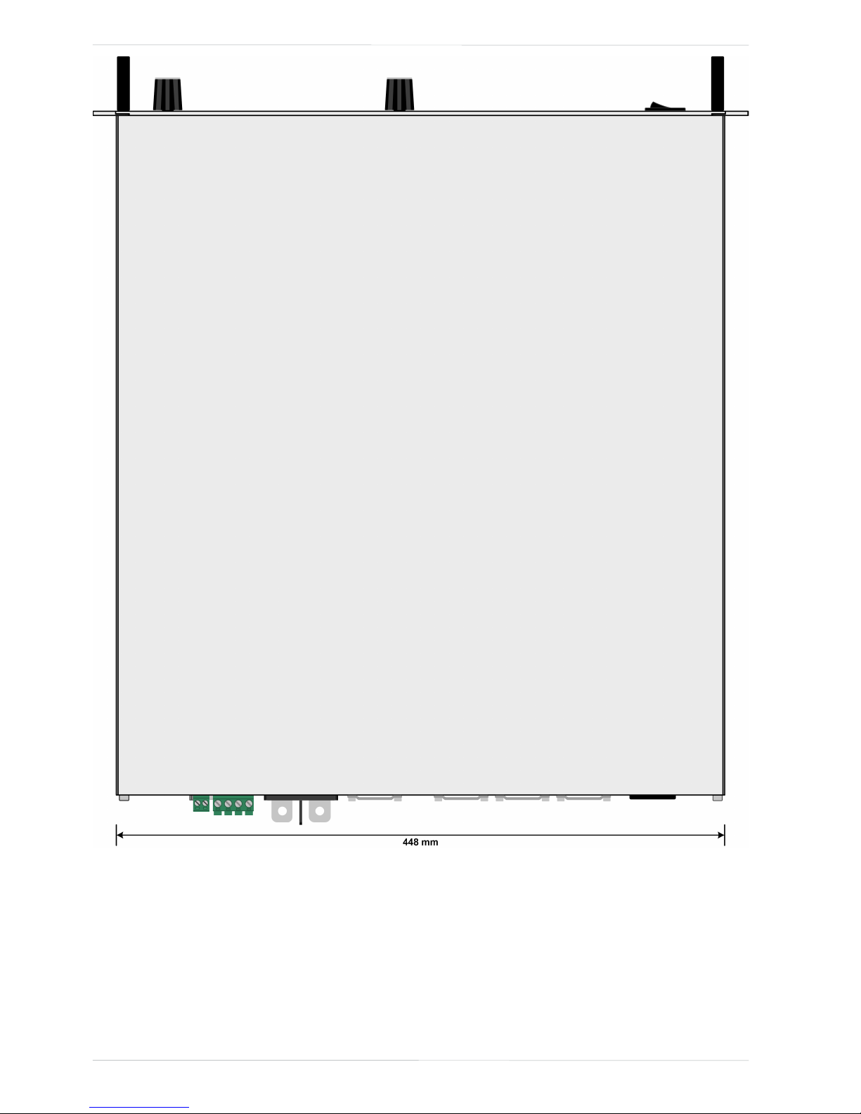
Figure 5 - Top view
17
PS 9000 1U Series
PS 9000 1U Series • DC Laboratory Power Supply • User Manual
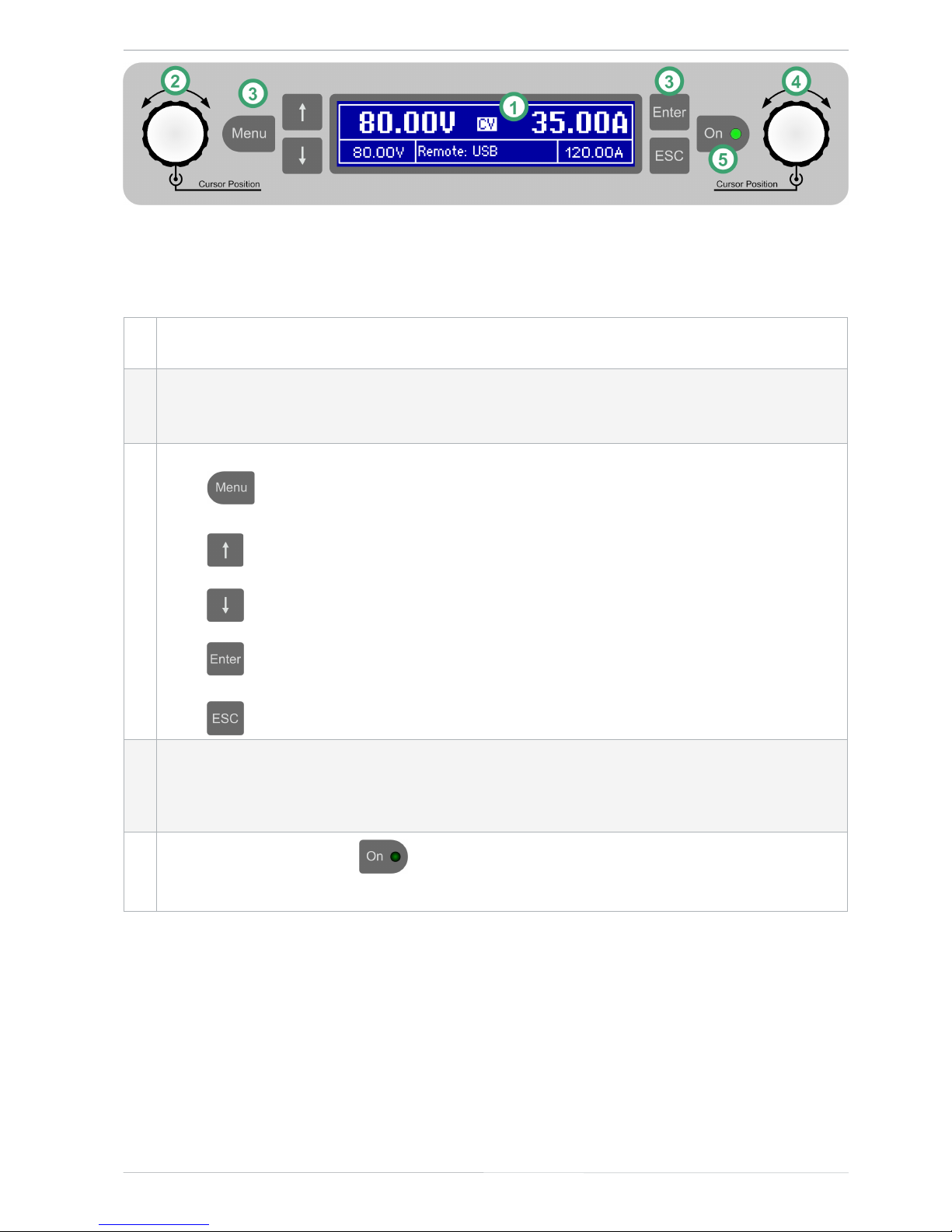
Figure 6 - Control Panel
Overview of the elements of the operating panel
For a detailed description see section “1.9.4. The control panel (HMI)”.
(1)
Display
Used for indication of set values, menus, conditions, actual values and status.
(2)
Left hand rotary knob, with pushbutton function
Turn: adjusts various set values which are related to the DC output voltage.
Push: selects the decimal position of a value to be changed (cursor)
(3)
Button bank
Button : Activates the setup menu for various device settings (see „3.4.3. Conguration in the setup
menu“)
Button : Navigates through menus, submenus and parameters (direction: up / left) or changes
view mode
Button : Navigates through menus, submenus and parameters (direction: down / right) or changes
view mode
Button : Submits altered parameters or set values in submenus, as well enters submenus. Can
also be used to acknowledge alarms.
Button : Cancels changes of parameters in the setup menu or leaves submenus
(4)
Right hand rotary knob, with pushbutton function
Turn: adjusts various set values which are related to the DC output current, the DC output power. Also
adjusts parameters in the setup menu.
Push: selects the decimal position of a value to be changed (cursor)
(5)
On/Off Button for DC output
Used to toggle the DC output between on and off, also used to acknowledge alarms. The LED indicates
the state of the DC output, no matter if the device is manually controlled or remotely (LED on = output on).
 Loading...