

Intense Lightin GD2WR, GD2WS Installation Instructions
Installation Instructions
For Use With Gravity 2-inch Remodel Wall Wash
(GD2WR & GD2WS)
ISR1087R2
1 of 5
WARNING
!
Risk of electric al shock. Disconnect power
before servicing or installing luminaire.
WARNING
!
Risk of injury or dam age. Luminaire will
fail if not instal led properly. Foll ow
installation instructions.
WARNING
!
Risk of injury. Wear safety glasse s and
gloves during ins tallation and servicing.
Allow ample time to cool bef ore handling.
IMPORTANT SAFETY INSTRUCTIONS
■ Read all installation instructions before installing. It is important to save these instructions.
■ Only install and connect LED module with power disconnected at the circuit breaker. Hot plugging, or connecting the module with
power on, could damage the LEDs and is not covered by warranty.
■ Connectors on modules and approved housing are keyed for specific voltage combinations; do not force or attempt to bypass
connectors.
■ Observe and follow all label information and instructions regarding dry, damp and wet location listings, proper Intense LED module,
warnings of installation near combustible materials and/or insulation.
■ Turn off power at circuit breaker before attempting to install or perform maintenance on the fixtures.
■ Be sure to connect ground wire to prevent electric shock or other potential hazards.
■ The product must be installed in a manner consistent with the intended use and in compliance with the national electrical codes and
local codes by a person familiar with the construction and operation of the product and the hazards involved.
■ Do not block the trim aperture as this may cause unsafe operating conditions.
■ WARNING: RISK OF FIRE. Non-IC fixture requires that insulation must be kept at least 3” away from all sides of the fixture.
Minimum of 90°C supply conductors. Consult a qualified electrician before installation.
WARNING:
Use only Intense Lighting trims listed for use with this fixture. Use of trims other than those listed by Intense Lighting is a
violation of N.E.C 1103(B) and voids all warranties.
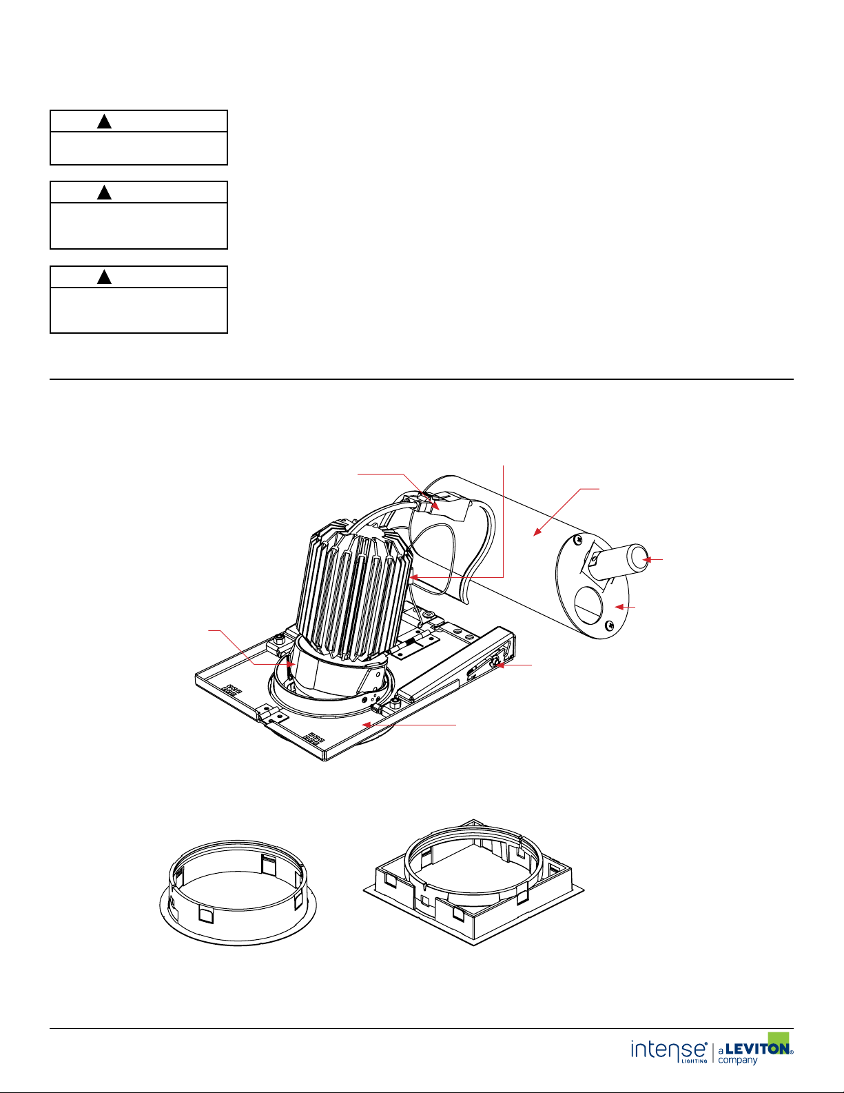
Main Housing View, Assembled
With Housing Components
Housing Lanyard
Module Quick Connect
Driver / Splice Housigs
Gravity 2-Inch
Module
Thermal Switch
Driver / Splice Cover Plate
Ceiling Height
Adjustment Hardware
Remodel Frame
Round Collar Square Collar
INSTRUCTIONS L/M-03302020 P-1
INTENSE LIGHTING | 3340 E L a Palma Ave, A naheim, CA 9 2806 | tel 714 630-9 877 | fax 714 630-9883
For Intense Lig hting’s limite d product war ranty, go to w ww.inte nselighting.com. For a prin ted copy of the warra nty, you may c all 800 961-5321.
© 2020 In tense Light ing, LLC. Al l rights res erved. No te: This docume nt is subject t o change with out notice.

Installation Instructions
For Use With Gravity 2-inch Remodel Wall Wash
(GD2WR & GD2WS)
ISR1087R2
2 of 5
COLL AR HEIGHT SETTING:
Before installing remodel frame into ceiling set tension to ceiling thickness as
indicated (Note: Ceiling adjustment hardware is NOT ACCESSIBLE BELOW
CEILING because of small aperture size)
■ 1/2” setting for single 1/2” sheet rock or laminated MDF (Fig. 1) (Note: 1/2”
minimum ceiling thickness)
■ 5/8” setting for single 5/8” sheet rock (Fig. 2) (Note: 5/8” maximum ceiling
thickness)
■ 1-1/4” setting for double 5/8” sheet rock (consult factory for thicker ceilings.
(Fig. 3) (Note: 1-1/4” maximum ceiling thickness)
*Sho wn As Inst alled*Sh own As Ins talled *Sho wn As Inst alled*Sh own As Ins talled *Sho wn As Inst alled*Sh own As Ins talled
1/2”
Ceiling Height
Adjustment Settings
1/2”5/8”1-1/4”
5/8”
Fig. 1 Fig. 2 Fig. 3
REMOVE COVER PLATE:
1. Remove (2) M3 pan head screws and junction box cover plate
2. 2. Remove knockout on cover plate and attach flexible conduit or RomexRemove knockout on cover plate and attach flexible conduit or Romex
enough conduit to ensure that driver box can be pulled through ceiling aper ture)enough conduit to ensure that driver box can be pulled through ceiling aper ture)
®®
cable ( cable (Note:Note: Use Use
3. Insure conduit connection clamp does not interfere with cover sitting flush
Note: Do not remove factory wiring, only pull cover plate out far enough to make electrical
connection to supplied power.
2 3
Ceiling Opening
Conduit/Romex
HOUSING INSTALL:
1. Insert driver housing through ceiling opening
2. Rest the driver housing in the ceiling plenum
3. Fold remodel frame and push assembly into
ceiling opening
Driver/Splice
Housing
4. Allow remodel frame to spring open and align
with ceiling opening
5. Insure module quick connector is accessible
Cover Plate
through opening
Ceiling Height
Adjustment Hardware
1-1/4”
1
COLLAR INSTALLATION:
1. 1. Push blue attachment clips flush against Push blue attachment clips flush against
ceiling. Align collar at blue attachment points ceiling. Align collar at blue attachment points
with blue clips.with blue clips. (See Fig. 1)
2. Grip attachment clip and pull tension down
below ceiling level and engage clip onto
attachment point (Fig. 2)
3. Repeat step on other side of collar w hile
holding collar in place
4. Collar should be flush against the ceiling and
clip evenly placed in position (see detail)
Pan Head (2 PCS)
2x Collar Attachment
Clip (Blue)
Below Ceiling Detail View
Flex Conduit
Module Quick
Connect
M3 x 6mm
Collar Attachment
Clip (2 Pcs)
Fig. 1 Fig. 2 Detail View
Remodel
Frame Edge
4
Correct Tension
Cable Alignment
Collar Clip Attachment Point
(Blue) Both Sides
INSTRUCTIONS L/M-03302020 P-2
INTENSE LIGHTING | 3340 E L a Palma Ave, A naheim, CA 9 2806 | tel 714 630-9 877 | fax 714 630-9883
For Intense Lig hting’s limite d product war ranty, go to w ww.inte nselighting.com. For a prin ted copy of the warra nty, you may c all 800 961-5321.
© 2020 In tense Light ing, LLC. Al l rights res erved. No te: This docume nt is subject t o change with out notice.
Correct Clip
Alignment
 Loading...