

user manual TRACER CARBON
introduction / registration 2
frame features / component spec 4
Geometry 5
exploded view and b.o.m. 6
Assembly 8
torque chart 13
setup 14
maintenance 18
AT INTENSE, WE H AVE ONE GOAL - TO P ROVIDE THE RIDE OF YOUR LIF E //
Our team of design ers, engineers a nd product exper ts are focused on one thing every
day: your experience o n the bike. We build bikes that are as thrilling to loo k at as they
are to ride, and we build t hem for the select few of you who underst and the difference
and refuse to settle for a nything else.
From the early days of Inte nse, when founder Jeff Steber worked a lone in his garage to
today, where a crew of tale nted people work in a Temecula, CA factor y, Intense has been
a brand built on pass ion by forward thinker s who, even today, love nothi ng more than
to throw a leg over a sweet b ike and head out for a rip. We’re so glad you’ve joined us.
Welcome to Intense, e njoy your experience.
THE TRACER C ARBON //
For the hardcore Endu ro rider, the Tracer Carbon is bui lt with a short rear en d for
quick maneuver s and a long front end wit h a slack, 65.5 degree head a ngle to keep
things stable. 165mm of rea r wheel travel on a stab le pedaling platfor m gets you up
the hills easily and st ill allows for big hits on the wa y down. No corner s were cut in
designing the eas ily serviceabl e pivots and lightweig ht carbon chassis b ut who needs
to cut corners whe n you’re on the fastest rig on the trail.
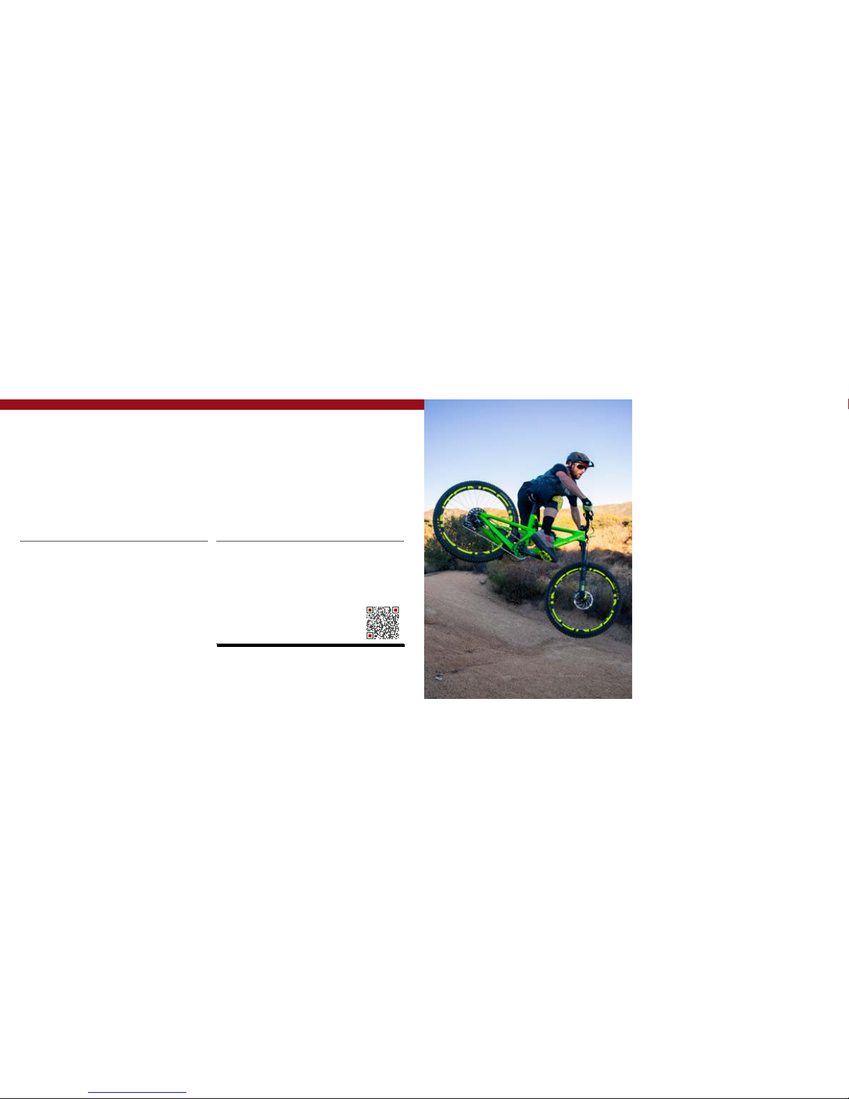
registration
WWW.INTENSECYCLES.COM/WARRANTY-CARD/
contact customer service
cs@intensecycles.com
951-296-9596
Welcome to
the family
2 // tracer carbon user manual INTENSE CYCLES // 3

4 // tracer carbon user manual INTENSE CYCLES // 5
frame
features /
spec
Geometry
A
B
C
F
E
D
G
H
L
K
I
J
GEOMETRY NOTEs
GEOMETRY TAKEN AT TOP O UT WITH 552MM
FORK LENGTH A ND 42MM FORK OFFS ET.
Component spec NOTE
the Tracer carbon is designed around
the use of a single c hain ring. Use of a
double or tripl e ring set will not a llow
proper cle arance with the f rame.
Frame Features //
• Travel: 6.5" (165mm)
• 27.5” Wheel size
• Integrated BOOST 148 x 12 dr opouts
• 6.15 lbs / 2,790 grams = Standard fr ame w/ alloy link, no sho ck
• 5.7 lbs / 2,568 grams = SL Supe r Light frame w/ carbo n link, no shock
• INTERNAL CABLE RO UTING
• Internal Seat Tube Cable R outing for droppe r posts
• Monocoque front triangle
• FLack GuaRD Downtu be and Chainstay protection
• Tapered Head Tube
• Angular Contact/Collet Be aring System with rep laceable Gre ase Zerks
Component Spe c //
• Fork – 1.5” tapered steer, 16 5mm Travel, 552mm lowe r leg length, 42mm of fset
• Shock – 216mm x 63.5mm (8.5” x 2.5”), 22mm x 6mm an d 22mm x 8mm reducers
• Seat post – 31.6mm
• Headset – Cane Creek , 40, Alloy Cartridge (w ww.canecreek.com)
• Bottom bracket - PF92
• Rear Axle – BOOST 14 8 x 12 T/A
• Brake Mount – post moun t - direct 180mm
• Crank set - BOOST 148 C ompatible - single ring only
• Rear Wheel - BOOST 14 8 Compatible
SMALL MEDIUM LARGE XLARGE
A Wheel Base: 1154 mm/ 45.4” 1181 mm/ 46.5” 1207 mm/ 47.5” 1235 mm/ 48.6”
B Top Tube Length: 571 mm/ 22.5” 597 mm/ 2 3.5” 622 mm/ 24.5” 649 mm/ 25.5”
C Chain Stay Lengt h: 432 mm/ 17” 432 mm/ 17” 432 mm/ 17” 432 mm/ 17”
D Head Tube Length: 102 mm/ 4” 115 mm/ 4.5” 119 mm / 4.7” 130 mm/ 5.1”
E Head Tube Angle: 65.5˚ 65.5˚ 65.5˚ 65.5˚
F Reach: 414 mm/ 16.3” 436 mm/ 17.2” 460 mm/ 18.1” 483 mm/ 19”
G Stack: 589 mm/ 23.2” 600 mm / 23.6” 604 mm/ 23.8” 614 mm/ 24.2”
H BB Height: 343 mm / 13.5” 343 mm / 13.5” 343 mm / 13.5” 343 mm/ 13.5”
I Seat Tube Angle (Effecti ve): 75˚ 75˚ 75˚ 75˚
J Seat Tube Angle (Actual): 7 1˚ 71˚ 71˚ 71˚
K Seat Tube Lengt h: 396 m m/ 15.6” 434 mm/ 17” 459 mm/ 18” 485 mm/ 19”
L Stan dover Height: 795 mm/ 31.3” 801 m m/ 31.6” 805 mm/ 31.7” 813 mm/ 32”
6 // tracer carbon user manual INTENSE CYCLES // 7
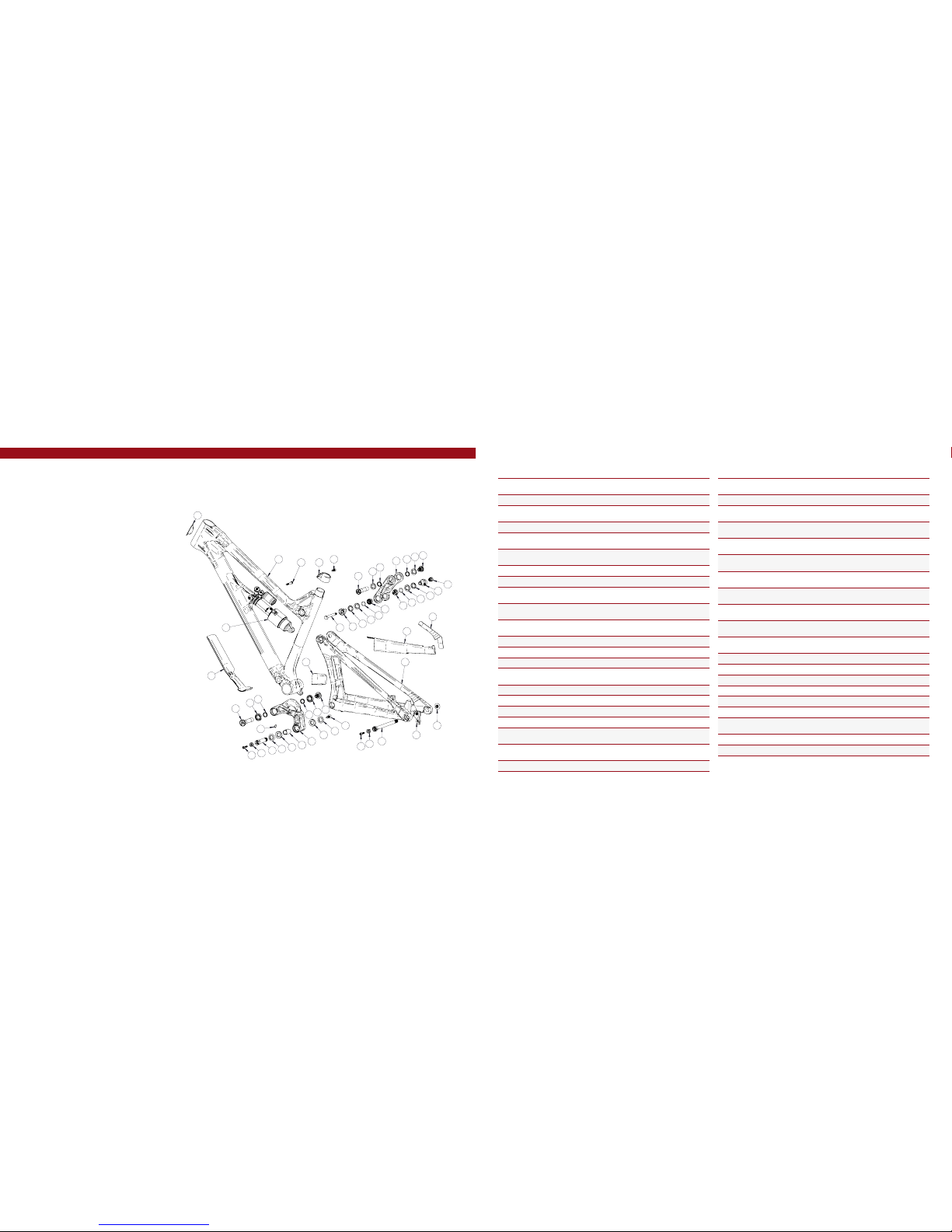
exploded view
and b.o.m.
36
38
22
29
5
29
6
39
33
10
1
8
3
7
25
16
4
28
4
21
28
27
37
9
34
24
29
3
29
31
13
19
7
17
14
20
12
22
15
30
7
7
30
11
26
23
12
18
16
25
2
32
ITEM
NO.
ITEM
PART
NUMBER
DESCRIPTION QT Y.
TORQUE
SPEC.
1
Rear Axle 130757 Axle 148 x 12 Boost 1
11 Nm /
100 in-lbs
2
Bearing Spacer 130758 Lower Link Bearing Spacer 1 N /A
3
Bearing Cap
24mm OD
130765
Top Link Bearing Spa cer
(Lower)
2 N/A
4
Bearing Cap 130778 Lower Lin k Bearing Cap 2 N /A
5
Axle Upper 130780
Top Link Pivot Axle
(Up per)
1
20 Nm /
175 in-lbs
6
Bolt Shoulder 130785 Top Link Pivot Bolt 1
20 Nm /
175 in-lbs
7
Spacer 130789 Bearing Spacer 4 N/A
8
Hanger 130790 Derailleur Hanger Forged 1 N/A
9
Bolt Main Pivot 130791 Lo wer Link Expander Bolt 1
7 Nm /
60 in-lbs
10
Hanger Bolt 130798 Derailleur Hanger Bolt 1
11 Nm /
100 in-lbs
11
Axle Lower 130800 Lower Link Axle 1
20 Nm /
175 in-lbs
12
Link Spacer 130801 Upper Link Spacer 2 N /A
13
D-Lock Reducer 130803 Non-Drive Side Reduc er 1 N /A
14
D-Lock Reducer 130805 Dr ive Side Reducer 1 N/A
15
Bolt Shoulder 130806 Lower Link Pivot Bolt 1
20 Nm /
175 in-lbs
16
Cone Adjuster 130807 Cone Adjuster B lk, 8.3 mm Height 2 N/A
17
Top Link Standard 130811 Forged Top Link 1 N/A
17
Top Link SL 130809 Carbon Top Lin k 1 N/A
18
Lower Link 130812 Forged Lower Link 1 N/A
19
Shock Bolt 130813 D-Lock Bolt 1
16 Nm /
140 in- lbs
20
Shock Bolt Nut 130814 D-Lock Nut 1
16 Nm /
140 in- lbs
21
Push Rivet 140038 Lower Link Push Riv et SR-0817BK 1 N/A
ITEM
NO.
ITEM
PART
NUMBER
DESCRIPTION QT Y.
TORQUE
SPEC.
22
O-Ring 140044
Upper LInk O-Rin g
13.8 mm ID x 2.4 mm Width
2 N/A
23
Seat Clamp 340342 Tracer Carbon S eat Clamp 1 N /A
24
Zerk Fitting
M6 x 1.0
401011 M6 x 1.0 1
5 Nm /
40 in-lbs
25
SHCS M6 x 22 410009
Cone Adjuster Bo lt,
Socket Head, M6 x 22
2
14 Nm /
125 in-lbs
25
SHCS M6 x 22 410032
Cone Adjuster Bo lt,
Socket Head, M6 x 22 Titani um
2
14 Nm /
125 in-lbs
26
SHCS M6 x 18 410048
Seat Clamp Bol t,
Socket Head, M6 x 18
1
14 Nm /
125 in-lbs
27
SHCS M6 x 40 410053
Front Shock Bolt ,
Socket Head, M6 x 40
1
7 Nm /
60 in-lbs
27
SHCS M6 x 40 410050
Front Shock Bolt ,
Socket Head, M6 x 40 Titan ium
1
7 Nm /
60 in-lbs
28
Bearing 7902 430007
15 x 28 x 7 2RS
MAX Angular Contact Bearing
2 N/A
29
Bearing 6802 430008
15 x 24 x 5 2RS
MAX Radial Bear ing
4 N/A
30
Bearing 6902 430009
15 x 28 x 7 2RS
MAX Radial Bear ing
2 N/A
31
Guard Flack DT 500269 Flac k Guard DT 1 N/A
32
Guard Flack CS 500270 Flack Guard Chainstay 1 N /A
33
Guard Flack Stst y 500271 Flac k Guard Seat Stay 1 N/A
34
Protector Chainstay 500272 Protector Chainstay 1 N /A
35
Decal 500300 Decal California Bear 1 N/A
36
Head Badge 500335 Head Badge Flame Logo 1 N/A
37
Rear Shock
8.5in x 2.5in
(215.9mm x 63.5mm)
1 N/A
38
Front Triangle Carbon - 4 Sizes 1 N/A
39
Rear Triangle Carbon - 1 Size 1 N /A
(ST)
(ST)
(ST)
(SL)
(SL)
(SL)

8 // tracer carbon user manual INTENSE CYCLES // 9
Assembly
Tools needed
• High Grade, waterproof greas e (Maxima Waterproof Grease r ecommended)
• Blue Loctite® #243
• 5mm HEX wrench x2
• 6mm hex wrench
• 8mm HEX wrench
• torque wrench
Recommendation
• APPLY A THIN COAT OF GREASE TO ALL P IVOT AXLES AND RE AR AXLE to REDUC E THE
CHANCE OF COR ROSION DUE TO MOISURE A ND PREVENT P OSSIBLE CREAKS .
• AFTER THE FIRST FE W RIDES THE COMPON ENTS Are BROKEN IN A ND SETTLED INTO
PLACE, GO T HROUGH AND RE TORQU E ALL PIVOT AXLES . AFTER THIS FIRS T ADJUSTMENT,
YOU WILL BE REA DY TO RIP FOR THE LONG HAU L.
• USE GREASE IN ANY ALL OY TO CARBON INTERFA CE, INCLUDING BB AN D HEADSET.
PR EFA CE //
Service and maint enance on an Inten se bicycle requir es special tools, a bilities and
knowledge of workin g on bicycles. It is alway s recommend ed to use an authoriz ed
Intense dealer for s ervice and maint enance. Always wea r eye protection. I t is critical
to use the proper t ools, loctite, grea se and torque spe cs during assem bly. Failure to
follow these instruc tions may result i n serious bodily injur y or death.
2 5
3 6
CONNECTING T OP LINK TO FRON T TRIANGLE //
A Holding top link (#130809) as oriented
in the above picture, w ith your fingertips,
hold upper link pivot bolt spacers
(#130789) against the inside of the
bearing races (IMAGE #1).
B Match upper link to pi vot point on the
top tube making su re the spacers do
not fall out.
C Using upper pivo t axle (#130780),
insert through n on-drive side of top link
bearing and push t hrough to drive side
bearing (IMAGE #2).
D Thread shoulder bolt (#130785) using
5mm HEX wrench. Hold ing 5MM wrench
on non-drive side an d 5MM torque wrench
on shoulder bolt , torque the assembly to
20 NM / 175 in/lbs (IMAGE #3).
CONNECTING B OX LINK TO FRONT TRIANGLE //
A Holding the lower l ink (#130812)
behind the seat tub e, use your fingertips
to hold lower link sp acers (#130789)
against the inside of t he bearing races
(I MA GE #4) .
B Slide over and matc h lower link to
pivot point on down tub e making sure
the spacers do n ot fall out (IMAGE #4).
C Using lower link pivot a xle (#130800),
insert through n on-drive side of lowe r
link bearing and pu sh through to drive
side bearing (IMAGE #5).
D Thread shoulder bolt (#130806) using
5mm HEX wrench. Hold ing 5MM wrench
on non-drive side an d 5MM torque wrench
on shoulder bolt , torque the assembly to
20 NM / 175 in/lbs (IMAGE #6).
1 4

10 // tracer carbon user manual INTENSE CYCLES // 1 1
INSTALLING RE AR SHOCK //
A Using rear shock with the reservoir
facing up, match the bod y and reservoir
with the front triangle s hock tabs. Insert
the M6 x 40MM shock bolt thro ugh the
assembly and t orque down to 14 NM /
125 in/lbs (IMAGE #18).
B Match the other end o f the shock with
the D-Lock reducer s and the link spacers
on the top link. Inse rt the keyed shock
shoulder bolt (#130813) making sure it
is keyed properly a nd is fully flushed with
the D-Lock reducer o n non-drive side
(IMAG E #19).
C Thread on shock nu t (#130814) with
5MM allen key and torque d own to 16 NM
/ 140 in/lbs (IMAGES #20, 21).
8
7
9 11
10 12 13
201814 16
211915 17
CONNECTING R EAR TRIAN GLE TO BOX LINK //
A Put a small dab of gr ease on the
outside bearing ra ce as well as on
the contacting surface of the bearing
cap (#130778). This will help hold
the bearing caps in p lace during the
instal lation (IMAGE #7).
B Slide rear triangle ov er the lower link
and line up the pivot p oint over the
bearing caps (IMAGE #8).
C Insert greased main pivot bolt
(#130791) into non-drive side of lower
link. Insert 8MM torq ue wrench and
torque main pivot b olt down to 7 NM /
60 in/lbs (IMAGES #9, 10).
D Grease and ins ert cone adjuster
(#130807) into main pivot bolt with M6
x 22MM bolt (#410009) (IMAGE#11).
Torque down to 14 NM / 125 in/lbs
(IMA GE #12).
E Insert push rive t (#140038) on the
drive side in the pivot a xle (IMAGE # 13).
CONNECTING R EAR TRIAN GLE TO TOP LINK //
A Put a small dab of grea se on the outside
bearing race as well a s on the contacting
surface of the bearin g cap (#130765).
This will help hold the b earing caps in
place during the installation (IMAGE #14).
B Swing the rear triangle u p aligning the
pivot point with upp er link bearing cap
(IMAGE #15).
C Insert the non-d rive D-Lock reducer
(#130803) and the drive side D-Lock
reducer (#130805), joining the top swing
link with the rear trian gle (IMAGE #16).
D Take the upper link spacer (#130801)
and slide it over the ba ck side of the
D-Lock reducer on bo th drive and nondrive sides. It will be a s nug fit as there
is a small o-ring fitted to t he inside
diameter of the tra cer spacer. This
spacer will direc tly interface with the
shock hardware (IMAGE #17).

torque
Achieving pro per torque is vital to
ensuring the sa fe performa nce and
function of the t racer carbon fra me.
Failure to do so coul d result in suboptimal performance of your frame
as well as prem ature wear and tear
of individual pa rts.
additional reference
In addition to this c hart, all torque
values are laser e tched onto
corresponding hardware for your
reference.
12 // tracer carbon user manual INTENSE CYCLES // 1 3
torque chart
20 Nm / 175 in/lbs
20 Nm / 175 in/lbs
16 Nm / 140 in/lbs
14 Nm / 125 in/lbs
M8 HEX 7 Nm / 60 in/lbs
M6 HEX 14 Nm / 125 in/lbs
Derailleur Cap: 11 Nm / 100 in/lb s
Axle (drive side): 11 Nm / 100 in/lbs
Axle (non-drive side): 14 Nm / 125 in/lbs
REAR AX LE //
A Insert 148 x 12MM rear axle (#130757)
into axle opening o n non-drive side
(I MA GE #24) .
B From drive side, insert 5MM a llen key
through the derail leur cap to reach the
5MM HEX interface on the axle. Turn
wrench in a counter c lockwise direc tion
to tighten and clock wise to loosen. Torque
to 11 NM / 100 in/lbs (IMAGE #25).
C Back on the non-dr ive side, use the
5MM allen wrench to tor que the cone
adjuster (#130807) with the M6 x 22MM
(#410032) down to 14 NM / 125 in/lbs
(IMAGE #26).
24
2625
2322
INSTALLING DERAILLEUR HANGER //
A Apply a thin layer of g rease to the
derailleur hanger (#130790) shank and
install into the keyed i nsert on the drive
side of the rear trian gle (IMAGE #22).
B Install derailleu r cap (#130798) using
a 6MM allen key and torque t o 11 NM /
100 in/lbs (IMAGE #23).

seat post
make sure to inse rt seat post at least 4” into th e main frame. A nything les s than
this amount co uld cause damage to t he frame or even fa ilure.
14 // tracer carbon user manual INTENSE CYCLES // 1 5
set up
4”
setting the sag
1. Rem ove fork and shock air caps and be sure you h ave a shock
pump and a small ru ler or measuring device handy.
2. Go a head and hop on the bike. Be sure to place al l your weight on the
seat with the dropp er in the up position and both hands o n the grips.
3. Giv e the bike 5-6 moderate bounces and sit ba ck down on the saddle.
4. Now have your friend sli de both the rear shock and the front fork
o-rings down against the s eal lip of the damper bodys (IMAGE #1).
5. Ste p off the bike nice and easy. Be sure to not compr ess the suspension
after the o-rings have be en set.
Pro Tip
Here is where having a f riend helps. Have the m straddle the fr ont wheel and pul l
the handle ba rs in a upward direction a s to not allow the su spension to comp ress
as you get off (image # 4).
6. Using your measuring device, measure the gap between the suspension
seal lip and the o-ring . Using the chart on the following page will tel l you
if you need more air p ressure or less air pressure (IMAGES #2, #3).
7. Adjust air pressure with yo ur shock pump accordingly (IMAGE #5).
8. Re-vis it steps 2-6 until your desired sag measure ment have been reached.
9. Install valve caps.
10. Go ri de your bike!
15% - 25%
While suspension
is compress ed on
fork or rear shoc k,
slide o-ring do wn
against the seal l ip
of damper body.
Release comp ression.
Measure gap from
o-ring to seal lip .
19mm
seatpost
PR EFA CE //
We are almost ready to ri p. Just a few
more checkpoints and adjustments
to ensure the per formance and ride
characteristics of the Tracer Carbon is
optimised for you.
Tools needed
• shock pump
• small ruler or measur ing device
recommendation
When setting u p the suspension sag ,
ask a fellow rip per to help. but if
alone, using a wal l to lean your
shoulder aga inst will do just fine .
4
21
3 5
cm 1 2 3 4 5 6 7 8 9 10

16 // tracer carbon user manual INTENSE CYCLES // 1 7
shock setup
FOX FLOAT x2 performance elite / x2
216 x 63.5mm
set up and tune
proper set up and tuning can vary
from shock to shock. Please
consult the Fox manu al included
with your bike for c omplete
information about set up, tuning
and general m aintenanc e or visit
www.foxrac ingshox.com
Travel 165mm
Shock Stoke
63mm
Shock Sag
30% when sitting o n the bike
Fork Sag
15-25% when sitting on the bi ke
SHOCK:
FOX Float X2 Perform ance Elite
SHOCK:
FOX Factory Float X2
RIDER WEIGHT(LBS/KGS) SPRING (PSI)
100 lbs/ 45 kgs
120 LSC 20
110 lbs/ 50 kgs
130 HSC 18
120 lbs/ 54 kgs
140 LSR 17
130 lbs/ 59 kgs
150 HSR 15
140 lbs/ 63 .5 kgs
160 LSC 18
150 LBS / 68 KGS
170 HSC 16
160 LBS / 73 KGS
180 LSR 14
170 LBS / 77 KG S
190 HSR 12
180 LBS / 82 KGS
200
190 LBS / 86 KGS
210 LSC 17
200 LBS / 91 KGS
220 HSC 14
210 LBS / 95 KGS
230 LSR 13
220 LBS / 100 KGS
240 HSR 10
230 LBS / 104 KG S
250
240 LBS / 109 KG S
n/a
n/a
250 LBS / 113 KG S
n/a
260 LBS / 118 KG S
n/a
270 LBS / 122 KG S
n/a
280 LBS / 127 KGS
n/a
290 LBS / 131 .5 KGS
n/a
300 LBS / 136 KGS
n/a
set up and tune
proper set up a nd tuning can
vary from shock to sh ock. Pleas e
consult the rockshox m anual
included with yo ur bike for complete
information about set up, tuning
and general m aintenanc e or visit
www.sram.com/rockshox/products
Travel 165mm
Shock Stoke
63 mm
Shock Sag
30% when sitting o n the bike
Fork Sag
15-25% when sitting on the bi ke
SHOCK:
Rock Shox Monar ch Plus R
SHOCK:
Rock Shox Monar ch Plus RT3
RIDER WEIGHT(LBS/KGS) SPRING (PSI) REBOUND (clicks out)
100 lbs/ 45 kgs
100
7-6
110 lbs/ 50 kgs
110
120 lbs/ 54 kgs
120
130 lbs/ 59 kgs
130
140 lbs/ 63 .5 kgs
140
150 LBS / 68 KGS
150
6-5
160 LBS / 73 KGS
160
170 LBS / 77 KG S
170
180 LBS / 82 KGS
180
190 LBS / 86 KGS
190
200 LBS / 91 KGS
200
210 LBS / 95 KGS
210
220 LBS / 100 KGS
220
230 LBS / 104 KG S
230
4-3
240 LBS / 109 KG S
240
250 LBS / 113 KG S
250
260 LBS / 118 KG S
260
270 LBS / 122 KG S
270
280 LBS / 127 KGS
280
290 LBS / 131 .5 KGS
290
300 LBS / 136 KGS
300
shock setup
rock shox monarch Plus r / rt3
216 x 63.5mm

18 // tracer carbon user manual INTENSE CYCLES // 1 9
maintenance
maintenance Schedule*
Action Every Ride
500 Miles or
1 Month
2000 Miles or 6
Months
4000 Miles o r
1 Year
Tires
Check air pres sure, inspect tread a nd sidewalls for tears an d punctures X
Chain
Brush off and lub ricate X
Brakes
Squeeze brakes and confirm function X
General
Clean comple te bike of mud and debris X
Headset
Check adjustment X
Box Link
Add grease thr u zerk fittings X
Frame Pivots
Check torques X
Spokes
Inspect for damage, check tension X
Shock and Fo rk
Check air pres sure, inspect for leak s X
Deraileur Cables
Inspect and lube X
Seatpo st
Clean and regrease interface with frame X
Frame Pivots
Remove pivot bo lts, check bearings for pi tting and wear X
Headset
Disassemb le stem, headset and for k. Check bearings for pit ting and wear X
Hubs
Pull wheels off, che ck hub bearings for pitti ng and wear X
Bottom Bracket
Remove crank ar ms and check BB bearin gs for pitting and wear X
Brakes
Replace brake pa ds X
Chain
Inspect for da mage and check for stretc hing X
General
Complete Tune-Up X
Shock and Fo rk
Overhaul See MFG Recommendations
GENERAL SE RVICE AND CARE //
You have purchased a high pe rformance bicycle which requi res a certain level of service
and maintenanc e to sustain the level of performanc e your frame was designed around.
Proper care will al so ensure the bike is safe to ride at all levels. I t is important to read
and understand t he carbon care information as well a s follow the maintenance sched ule
and inspect you r bicycle before each ride. These wil l not only help to limit or avoid costl y
repairs but will als o help to avoid injury due to service negle ct and component failure.
carbon care
Intense Cycles e mploys advanced c omposite tech niques and material s in
our frames wh ich do require a certain lev el of care and main tenance to
ensure a safe e xperience at the high le vel of performa nce each fra me is
designed aroun d. Not following the se guidelines will dec rease the leve l
of performa nce and possibly cause in jury or death.
• Use a so ft cloth with warm soapy water to clean the ca rbon surfaces. Do
not use abrasive c loths or cleaners.
• Be sure a ll frame surfaces in contact with cable s are protected. Cable
housing rubbin g on carbon can wear over time.
• Be sure b rake levers, handle bar ends and th e fork crown do not co ntact
the frame at full rotation.
• Never cl amp any part of a carbon frame in a bike stan d or car rack.
• Always in spect your frame if you experience a ny chain suck. Intense
frames come equi pped with steel chain suck plates but d amage can still
be done in the event of c hain suck.
• Always in spect your frame in full after a crash to be su re there is no
damage. Look for crac ks, dents or loose fibers. If you disco ver damage
in any degree it’s best to have yo ur frame inspected by a qualified
Intense Cycles dea ler. Any direct impa ct to the frame can cause serious
structural damage.
• Use high g rade waterproof grease on seat po st, BB and head set bearing
contact areas with the carbon.
• Never re am or face a carbon frame.
• Be sure t o follow all recommended torque s ettings.
* THE ABOVE MAINTENANCE SCHEDULE IS ONLY A GUIDELINE. refer to COMPONENT MANUFACTURER FOR SPECIFIC INSTRUCTION ON MAINTAINING THEIR PARTS.

phone: (951)-296-9596
Customer Service: cs@intensecycles.com
General Info: info@intensecycles.com
Media, Marketing, Sponsorship: marketing@intensecycles.com
Intense Cycles USA 42380 rio nedo Temecula, Ca. 92590
www.I NTENSeCYCLES.com
330021
 Loading...