

Page 1
USER MANUAL // TAZER
Page 2

table of contents //
Introduction / Registration 2
Unboxing 4
Get Charged / Build 5
Connect the System . 7
Suspension Setup 8
Frame Features / Component Spec 10
Geometry 11
Exploded View an d B.O.M. 12
Torque Chart 15
Unique Identi ers 16
About the Batter y 17
Installing / Removing B attery 20
Turning the Power On / Off 22
Cycle Computer Di splay and Setting 23
Assist and Shif t Switches 24
Maintenance 26
Troubleshooting 28
E-bike Declaration of Conformity 30
At Intense, we have one goal -
to provide the ride of your life //
Our team of designer s, engineers and pro duct experts ar e focused on
one thing every day: your ex perience on the bike. We build bikes that
are as thrilling to lo ok at as they are to ride, and we bui ld them for the
select few of you who unde rstand the difference and ref use to settle for
anything else. From the e arly days of Intense, when founder Jeff S teber
worked alone in his gara ge to today, where a crew of talented people wo rk
in a Temecula, CA factory, Intense has b een a brand built on passion by
forward thinker s who, even today, love nothing more than to throw a leg
over a sweet bike and head out for a ri p. We’re so glad you’ve joined us.
Welcome to Intense, enjoy yo ur experience.
the tazer //
More than an eBike, thin k of the Taze r as an Intense bike that happens
to have an E-assist featur e. Built with aggress ive trail geometr y, Jeff
Steber tuned kinema tics and 29”/27.5” front and rea r wheel sizes, this
bike delivers a unique ri de for an eMTB that won’t feel cumber some and
has a seamless pedal -to-power transition.
#NOSHUTTLEREQUIRED
register your bike //
www.intensecycles.com/warranty-card/
technica l assistance
techcenter@intensecycles.com
951 -30 7-92 11
Welcome to
th e fam i ly
2 // tazer user manual INTENSE CYCLES // 3
Page 3
4 // tazer user manual INTENSE CYCLES // 5
setup
Preface //
Before you can get out th ere and rip up the trail s,
we need to get your bike unpacked and b uilt up.
This is a good chanc e for you to become fami liar
with your bike and to ensure th e performance and
ride character istics of the Tazer is optimised for you .
Tools needed
• sho ck pump
• small r uler or measuring device
• torque wrench
• I ntense Carbon Paste
Unboxing your tazer //
Careful attentio n has been given to the packaging of your Intense Tazer
to not only ensure that it ar rives safely and und amaged, but also that
you are able to re-us e the packaging for situations in whi ch you need to
safely transpor t your bike.
1. Rest the box on the ground or stable surface
with the top side facing up.
2. Pull the aps and open the top l id.
3. Remove the INTEN SE accessory box, which contains
your user manual, torque wrench, and shock pump.
4. Everything in the box is numbere d. Remov e the in serts
in chrono logical order taking care n ot to rip or tear th e
cardbard s o that th ey can b e reused in the future .
5. After removing the h andleba r and contro l protector (#7), raise the
dropper post by activating the trigger located on the handlebar.
6. Mount the frame onto a bike stand using the seatpost as your
clamp ing surface. WARNING: Do not clamp onto any of the carbon
surfaces of the frame as this could severely damage the frame.
7. Co ntinue by remov ing the remainin g protectors from the bike.
Get charged //
The battery is no t fully charged at the time of pur chase, so before you start
building your Tazer, take a moment to unpack and c harge the supplied
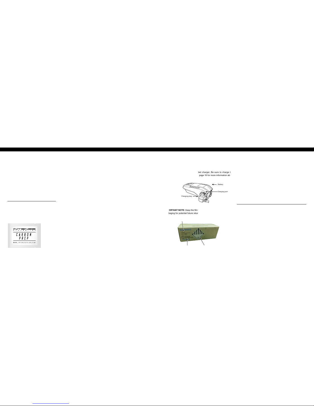
Shimano batter y using its dedicated c harger. Be sure to charge the
battery until it i s fully charged. See page 18 for more informat ion about
charging the battery.
Charging plug
Battery
Charging port
IMPORTANT NOTE: Keep the Shimano battery box and original internal
packaging for potential future returns to Shimano.
packaging identifiers
1. Frame spacer
2. Wheel stabil izer (fro nt wheel)
3. Wheel stabil izer (rear wheel)
4. Rear wheel cover
5. Front wheel cover
6. Cassette cover
7. Handlebar and
contro l protector
8. Fork cover
9. Downtube / toptube protector
building your tazer //
Once all the protec tors have been removed from the bike, we can beg in
the process of mou nting the components onto the frame.
Handlebar Installation
1. Spin the stem around so that the faceplate is facing forward.
2. Using a 4 mm allen key, remove the faceplate from the stem.
3. Making sure that all the cables are oriented properly, place
the handlebar into the stem and reinstall the facep late.
With the handlebar centered, torque the faceplate bolts to
6 Nm / 54 in-lbs. NOTE: Take your time when installing the
faceplate bolts to prevent any type of cross threading.
p r o t i p
When installing th e faceplate, always tight en the stem bolts in a cro ss
pattern (top left – bo ttom right, bottom left – Top right).
Mounting the Derailleur
1. Using a knife or scissors, carefully remove the bubble wrap
and z ipties fro m the rear d erailleur, ch ain, and B-s crew.
2. With a 5mm allen key, mount the rear derailleur onto the
derailleur han ger being care ful to avoid cross threading .
3. Using a torque wrench, tighten the derailleur
bolt to 8-10 Nm / 70-90 in-lbs.
UN number
Hazardous goods labelPackaging code
Page 4
6 // tazer user manual INTENSE CYCLES // 7
Installing the rear wheel
1. Remove the brake pad sp acers from the rear brake. Be sure
to keep this in a safe spot so it c an be reused in the future.
2. Remove the rear axle.
3. Grab the rear wheel and c arefully remove the disc
guard. Check the disc gu ard to make sure the end
cap is not accident ally removed with the guard.
4. Pull the derailleur back an d slide the rear wheel
into the rear triangl e of the bike, setting the chain
on the smallest gear of t he cassette.
5. From the non-drive sid e, slide the axle through the dropo ut and
wheel assembly, threading i t by hand in a clockwise directio n.
6. Using a 5mm allen key from the dr ive side, tighten the axle in
a counter clock wise direction. Torque to 11 Nm / 100 in-lbs.
7. From t he non-drive side, tighten the c one spacer with
a 5mm allen key. Torque to 14 Nm / 125 in-lbs.
Installing the front wheel
1. Grab the front w heel and carefully remove the disc guard.
2. Remove the front axle as well as t he pad spacer from the front
brake. Be sure to keep the pad spac er in a safe spot for future use.
3. With the rotor side of the wh eel on the non-drive side
of the bike, line the brake cali per up with the disc rotor
carefuly sliding th e front wheel between the fork le gs.
4. Slide the axle through t he fork dropout and wheel assemb ly
and tighten by turning in a c lockwise direction. NOT E: To
prevent accidental opening of the quick release lever while
riding, always lock t he lever in an upward direction (paralle l
to the fork leg) or horizo ntally towards the rear of the bike.
Quick Component Check
All INTENSE bicyc les are delivered " Ride Ready", meaning you c an
expect the bikes to com e with the brakes and dr ivetrain all proper ly
adjusted. However, to ensure that nothing happened during shipping,
we recommend that you c heck that all the c omponents are oper ating
correctly bef ore heading out to the trail.
1. One wheel at a time, sp in the wheels to make sure there
is no rotor rub from th e brake pads. Give the brakes a
squeeze to make sure every thing feels alright.
2. Check that the derailleu r is adjusted properly by
running up and down th e gears making sure that
everything is functioning nice and smoothly.
setting preload on the h eadset
and tightening the stem
1. Remove the bike from the st and and place it onto the ground.
2. Check that front wheel is i nline with the stem.
PRO TIP: You can line up the back of the ha ndlebar with
the front of the fork c rown to help with alignment.
3. Set the preload on the heads et by tightening
the bolt in the center c ap.
4. Tighten stem bolts with 5m m allen key
and torque to 8 Nm / 70 in-l bs.
connecting the system //
Now that your bike is built, we n eed to plug the electric wire that c an be
found coming out of th e down tube (drive side) into the back of the cycling
computer as shown be low.
seat po st
When insertin g the seat post, apply a li beral coat carb on paste and
gently slide it into the se at tube. With a minimum se at post insertio n of
4" (100mm), tighten seat post clamp to 5 Nm / 4 5 in-lbs. NOTE: Over
tightening the seat po st clamp will inhibit the movement of the sea t post
and potentially damag e seat post and/or seat tube.
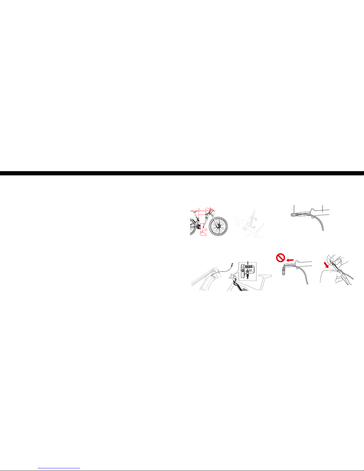
connecting the electric wire
Use the Shimano original tool (TL-EW02) for installation and removal of
the electric wi re. Set so that the projec tion on the conne ctor is aligned
with the groove on the nar row end of the tool.
When installing th e electric wire, do n ot forcibly bend the c onnector. It
may result in a poor cont act. When connecting the elec tric wire, push it
in until it clicks in plac e.
Connector
Shimano Installation Tool
(TL- EW02 )
min. seat height
4”
(100m m)
Page 5
8 // tazer user manual INTENSE CYCLES // 9
Travel
155 mm (6.1")
Shock Stroke
55 mm (2.15")
Shock Sag
30% when sitt ing on the bike
Fork Sag
20% when sitti ng on the bike
Shock
Fox Float DPX2 Sho ck 185 x 55 mm
RIDER WEIG HT
(LBS/KG S)
Air Pressure
(PSI)
REBOUND
(clicks out fr om fully close d)
Closed is Clockwise
Open is Counter Clockwise
Low Speed
Compression
100 lbs/ 45 kgs
130 11
10 Clicks Out
110 lbs/ 50 kgs
145 10
120 lbs/ 54 kgs
160 9
130 lbs/ 59 kgs
175 9
140 lbs/ 63 .5 kgs
190 8
150/ 68 kgs
205 8
8 Clicks Out
160/ 73 kgs
220 7
170/ 77 kgs
235 7
180/ 82 kgs
250 6
190/ 86 kgs
265 6
200/ 91 kgs
280 5
6 Clicks Out
210/ 95 kgs
295 5
220/ 100 kgs
310 4
230/ 104 kgs
325 3
240/ 109 kgs
340 2
250/ 113 kgs
350 2
shock setup //
Proper set u p and tuning can vary fro m sh ock to shock. Please c onsult
the Fox manual included w ith your bike for complete i nformation abou t
set up, tuning and general maintenance or visit www.foxracingshox.com
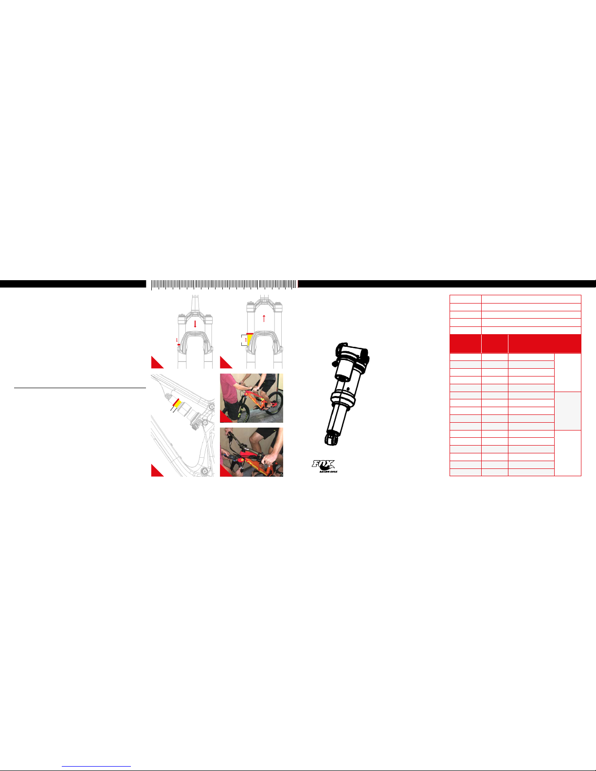
setting the sag //
1. Remove fork and shoc k air caps and be sure you have a
shock pump and a small r uler or measuring device handy.
2. Go ahead and hop on the bike. Be sur e to place
all your weight on the seat w ith the dropper in the
up position and both h ands on the grips.
3. Give the bike 5-6 mo derate bounces and
sit back down on the sad dle.
4. Now have your friend slide bot h the rear shock and the front fork
o-rings dow n against the seal lip of the damper bodys (I mage #1).
5. Step off the bike nice and easy. Be sure to n ot compress
the suspension af ter the o-rings have been set.
P r o T i p
Here is where having a fr iend helps. Have them st raddle the front
wheel and pull the hand le bars in a upward direction as to not allow th e
suspension to comp ress as you get off (Image #4).
6. Using your measuring devic e, measure the gap between
the suspension seal l ip and the o-ring. Using the ch art
on the following pag e will tell you if you need more air
pressure or less air p ressure (Images #2, #3).
7. Adju st air pressure with your shock pump ac cordingly (Image #5).
8. Re-visit steps 2-6 unt il your desired sag
measurement have been reached.
9. Install valve caps.
20%
(30mm)
While suspension
is compressed on
fork or rear sho ck,
slide o-ri ng down
against the sea l lip
of damper body.
Release compression.
Measure gap fro m
o-ring to se al lip.
4
21
3 5
cm 1 2 3 4 5 6 7 8 9 10
30%
(16.5m m)
FOX FLOAT dpx2
185 x 55mm
NOTE:
• FLOAT DPX2 shocks have a maximum
pressure of 35 0psi (24.1 bar).
• Max rider weight for the DPX 2 shock on
the Tazer is 250 lbs / 113 kg based on
30% sag require ment and DPX2 shoc k
max air pressu re of 350 psi.
• Max rider weight for TAZER f rame
is 300 lbs / 136 kg.
• Please contact the Inten se Cycles Tech
Center for shoc k tment options.
Page 6
10 // tazer user manual INTENSE CYCLES // 1 1
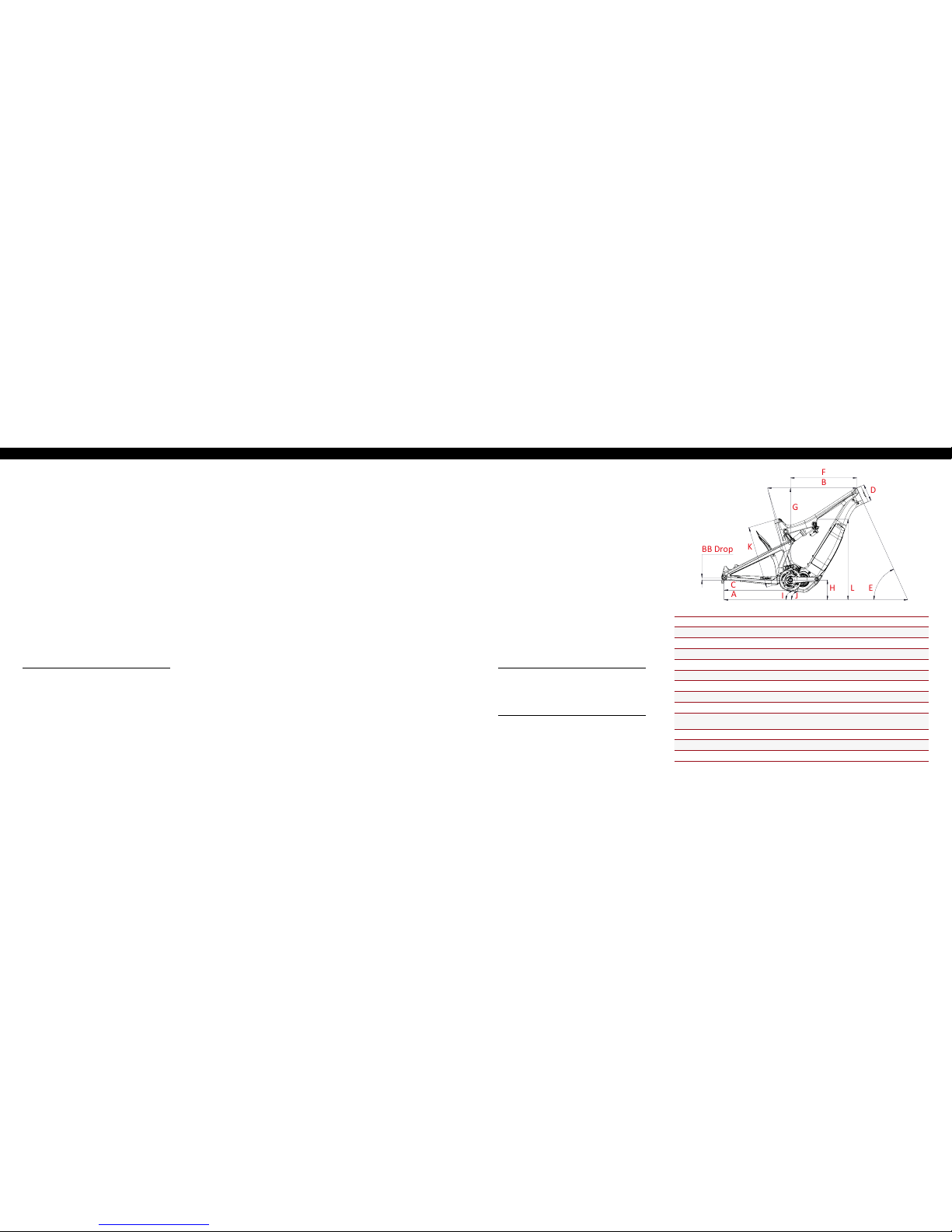
Geometry //
A
B
BB Drop
C
F
E
D
G
H
L
K
I
J
GEOMETRY NOTE
Geometry taken at top out with 567mm axle to
crown length and 51mm fork of fset.
Component spe c NOTE
The Tazer is designed around th e use of a single
chain ring only. Use of a doubl e or triple ring set will
not allow proper cle arance with the frame.
Frame Features //
• Rear Travel: 155mm / 6.1
inches with metri c 185 x 55
stroke shock
• 29” Front Wh eel size, 27. 5” x
2.80” Plus Rear Wh eel size
• Progressive Shock Curve
• Integrated 148 x 12mm
dropouts
• Internal Cable Routing
• Flack Guard: Downtube,
Chainstay, Seatstay and
Seattube protection
• Molded: Rear Fender
• Tapered Head Tube
• Replaceable Grease Zerk on
back of Lower Link
• Max Bea rings and Dedicated
Frame Hardware
• Molded Skid plate
• Removable Battery
Component Spec //
• Fork: Acc epts 1.125” straig ht
steer or 1.125”/1.5” tapered
steer, 160mm travel/ 6.3
inches, 567mm A xle to Crown,
51mm O ffse t
• Shock : 185mm x 55mm Metric
Shock, Trunnion with 20 mm x
8mm Reducers on sho ck
• Seat po st: 31.6mm
• Headset: Z ero Stack 49mm
Upper/ 56mm Lower
• Rear A xle: BOOST 148 x 12mm
• Brake Mount : Post Mount for
200mm rotor
• Shimano E8 000 Motor
• Shimano E8 010 Battery
SMALL MEDIUM LARGE
A
Wheel Base: 1199.4 mm/ 47.2” 123 0 mm/ 48.4” 1260 mm/ 49.6”
B
Top Tub e Len gth: 577 mm/ 22.7” 605 mm/ 23 .8” 633.4 mm/ 25”
C
Chain Stay Length: 450 mm/ 17.7” 450 mm/ 17.7” 4 50 mm/ 17.7”
D
Head Tube Length: 10 0 mm/ 3.94” 115 mm/ 4. 5” 125 mm/ 4.9”
E
Head Tube Angle: 64.9˚ 64.9˚ 64.9˚
F
Reach: 425 mm/ 16.7 ” 450 mm/ 17.7” 475 mm/ 18.7”
G
Stack: 610 m m/ 24” 623 mm / 24.54” 632 mm/ 24. 9”
H
BB Height: 347 mm/ 13.65” 347 mm/ 13.65 ” 347 mm/ 13.65”
BB Drop 12 mm/ 0.47” 12 mm/ 0.47” 12 mm/ 0.47”
I
Seat Tube Angle
(Effective):
75.4˚ 75.4˚ 75.4˚
J
Seat Tube Angle (Actual): 72.9˚ 72.9˚ 72.9˚
K
Seat Tube Length: 394 m m/ 15.5” 419 mm/ 16.5” 445 mm/ 17.5”
L
Standover Height: 806 mm/ 31.7” 814.1 mm/ 32” 8 22 mm/ 32.4”
getting to
know your
tazer
W A R N I N G
Use the supplied key to remove t he battery from the
frame to perform battery swap or for charging. Do
not move or alter the batte ry frame mounts from th eir
factory posit ion in the downtube as this could r esult
in subpar perfor mance, may lead to battery and or
frame damage and is not c overed under warranty.
Please contact Intense Cycles Tech Center if you
have any questions relatin g to the battery mounts.
Page 7

12 // tazer user manual INTENSE CYCLES // 1 3
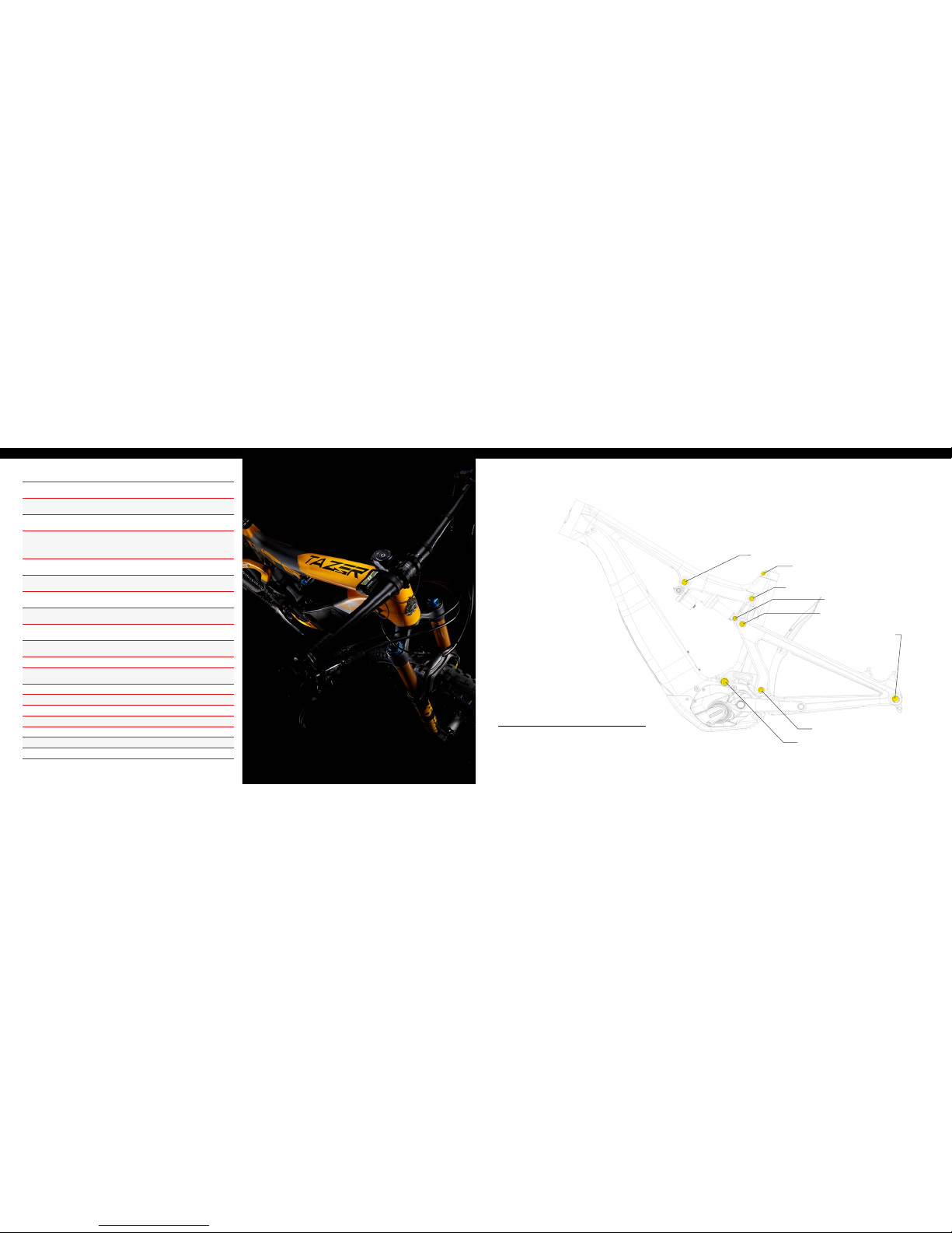
exploded view and b.o.m. //
52
15
45
24
28
54
47
15
26
36
20
41
44
3
12
14
10
44
3
3
8
6
2
56
55
22
23
43
5
46
37
11
39
1
4
17
7
9
38
13
23
23
44
3
19
9
38
44
38
9
43
46
17
4
28
28
25
45
16
16
42
34
40
49
48
29
57
50
42
42 21
27
21
22
18
18
32
33
30
31
Foam in Door Latch
53
9
38
51
35
(continued on next page)
ITEM
NO.
ITEM
PART
NUMBER
DESCRIPTION Q TY. TORQUE SPEC.
1
Bearing Spacer 130754 Lower Link Bearing Spacer 1 N/A
2
Rear Axle 130757
Axle Rear
148 x 12mm Boost
1
11 Nm /
100 in-lb s
3
Bearing Cap 130765
Upper Link Bear ing Cap,
24mm
4 N/A
4
Bearing Cap 130778 Lower Link Bea ring Cap, 28mm 2 N/A
5
Pivot Bolt 130785 Lower Link Pi vot Bolt 1
20 Nm /
175 in-lbs
6
Hanger 13 0790 Derailleur Hanger, Forged 1 N/A
7
Pivot Bolt 130795
Lower Link Expa nder Bolt
(Lower Pivot)
1
7 Nm /
60 in-lbs
8
Hanger Bolt 130798 Derailleur Hanger Bolt 1
11 Nm /
100 in-lb s
9
Cone Adjuster 13080 7
Cone Adjuster,
8.3 mm Height
4 N/A
10
Bearing Spacer 130847
Upper Link Bear ing Spacer
(Upper Pivot)
1 N/A
11
Lower Link 13 0848 Forged Lower Link Tazer, Blk 1 N/A
12
Forged Top Link 13084 9 Forged Top Link Tazer, Blk 1 N/A
13
Axle Lower 130850 Axle Lower Pi vot Tazer 1
20 Nm /
175 in-lbs
14
Bearing Spacer 1308 51
Upper Link Bear ing Spacer
(Lower Pivot)
1 N/A
15
Bearing Spacer 130852
Shock Mount Be aring
Spacer (Trunio n Pivot)
2 N/A
16
Shock Bolt 130853 Trunion Pivot Shock Bolt 2
16 Nm /
140 in-l bs
17
Bearing Spacer 130860
Lower Link Bear ing Spacer
(Upper Pivot)
2 N/A
18
Drive Unit Bolt 13 0862
Drive Unit Bolt M 8 x 18 with
T40 Br oach
4
10 Nm /
88 in-lbs
19
Pivot Bolt 130863
Upper Link Exp ander Bolt
(Upper Pivot)
1
7 Nm /
60 in-lbs
ITEM
NO.
ITEM
PART
NUMBER
DESCRIPTION Q TY. TORQUE SPEC.
20
Pivot Bolt 130864
Upper Link Exp ander Bolt
(Lower Pivot)
1
7 Nm /
60 in-lbs
21
Skidplate
Spacer
130867 Skidplate Spac er 2 N/A
22
FHCS M8 x 30 130868
Drive Unit/ Skid Plate Bolt
M8 x 1.25 x 30 mm
2
10 Nm /
88 in-lbs
23
Plug 140 038 Lower Link Pivot Plug 3 N/A
24
Cable Guide
Plug
140039 Cable Guide Plug, So lid 1 N/A
25
Cable Guide
Plug
140040 Guide Cable P lug, 5mm ID 1 N/A
26
Battery Door 140050 Battery Door 1 N/A
27
Skid Plate 1400 51 Skid Plate 1 N/A
28
Cable Guide
Plug
140052 Guide Cab le Plug, 4mm ID 3
29
Rear Fender 140054 Rear Fender 1 N/A
30
Battery Pul l
Strap
140055 Battery Pull St rap 1 N /A
31
Foam Pad 140056 Battery Do or Foam Pad 1 N/A
32
Gasket 140057 Bat tery Door Gasket 1 N/A
33
Foam Pad 140058
Battery Co mpartment
Foam Pad
1 N/A
34
Battery Cha rge
Window
140059 Battery Charge Window 1 N/A
35
Grommet 1400 60
Speed Sensor Wire
Grommet
1 N/A
36
Seat Clamp 340342 Bolt-on Seat Clamp 1 N/A
37
Zerk Fitting 401011 M6 x 1.0 1
5 Nm /
40 in-lbs
38
SHCS M6 x 2 2 410009
Cone Adjuster B olt, Socket
Head, M6 x 22
4
14 Nm /
125 in-lbs
Page 8
14 // tazer user manual INTENSE CYCLES // 1 5
ITEM
NO.
ITEM
PART
NUMBER
DESCRIPTION Q TY. TORQUE SPEC.
39
BHCS M5 X 12 410010
Skid Plate Bolt , Button
Head, M5 X 12
2
6 Nm /
54 in-lbs
40
SHCS M8 x 35 4100 45 Sh ock Bolt, M8 x 35 Steel 1
16 Nm /
140 in-l bs
41
SHCS M6 x 18 410 048
Seat Clamp Bolt , Socket
Head, M6 x 18
1
5 Nm /
45 in-lbs
42
M5 x 11 4100 68
Fender / Skidpla te Bolt, Low
prole Socket Head, M5 x 11
5
1 Nm/9 in -lbs
(Fender)
2 Nm/18 in-lbs
(Skidplate)
43
Bearing 7902 430007
15 x 28 x 7 2RS
MAX Angular Contact Bearing
2 N/A
44
Bearing 6802 430008
15 x 24 x 5 2RS
MAX Radial Bearing
4 N/A
45
Bearing 6800 430011
10 x 19 x 5 2RS
MAX Radial Bearing
2 N/A
46
Bearing 3802 430014
15 x 24 x 7,
Double Row Radia l Bearing
2 N/A
47
Flack Guard
Downtube
500301
Flack Guard Tazer
Downtube
1 N/A
48
Flack Guard CS 5003 02
Flack Guard Tazer
Chainstay
1 N/A
49
Flack Guard 500303 Fla ck Guard Tazer Seatstay 1 N /A
50
Flack Guard 500304
Flack Guard Tazer
Seat Tube Protector
1 N/A
51
Flack Guard 500305 Flack Guar d Tazer RT Strut 1 N/A
52
Head Badge 500335 H ead Badge Flame Logo 1 N/A
53
Rear Shock 185 x 55, Trunnion 1 N/A
54
Battery Shimano E8010 1 N/A
55
Front Triangle Carbon, 3 Sizes 1 N/A
56
Motor Shimano E8000 1 N/A
57
Rear Triangle Ca rbon, 1 Size 1 N/A
16 Nm / 140 in-lbs
5 Nm / 45 in-lbs
16 Nm / 140 in-lbs
M8 HEX 7 Nm / 60 in -lbs
M5 HEX 14 Nm / 125 in-l bs
20 Nm / 175 in-lbs
M8 HEX 7 Nm / 60 in -lbs
M5 HEX 14 Nm / 125 in-l bs
M8 HEX 7 Nm / 60 in -lbs
M5 HEX 14 Nm / 125 in-l bs
Derailleur Ca p: 11 Nm / 100 in-lbs
Axle (non- drive side): 11 Nm / 100 in-lbs
Adjuster cone (no n-drive side): M5 H EX
14 Nm / 125 in-lbs
torque specifications //
Achieving proper torque is vital to ensuring the safe performance and function
of the tazer frame. Failu re to do so could result in sub- optimal performance
of your frame as well as prem ature wea r and tear of individual parts.
additional reference
In addition to this ch art, torque values are laser etched
onto corresponding hardware for your reference.
Page 9

about the battery //
16 // tazer user manual INTENSE CYCLES // 1 7
DANGER
Use the Shimano specied c harger and observe the specied charging
conditio ns when charging the sp ecied batter y. Not doing so may cause
overheating, bursti ng, or ignition of the battery.
CAUTION
• W hen removing the battery cha rger power plug from the outlet or the
charging plug fro m the battery, do not pull it out by the cord.
• Whe n charging the battery wh ile it is mounted on the bicycle, be c areful
not to trip over the charg er cord or get anything caugh t on it. This may
lead to injury or c ause the bicycle to fall over, damaging the co mponents.
RIDING THE BICYCLE
1. Turn on the power.
a. You cannot use the battery immed iately after shipment.
Refer to ”CHARGIN G THE BATTERY”
b. Do not place your feet on the pe dals when turning
the power on. A system erro r may result.
c. Power cannot be turne d on while charging.
2. Sel ect your preferred assist mode.
3. As sistance will start when th e pedals start turning.
4. Chan ge the assist mode in accordanc e with the riding conditions .
5. Turn the power of f when parking the bicycle.
a. Do not place your feet on the peda ls when turning
the power off. A system er ror may result.
Intense bicycle identification //
It’s important to kee p track of your Tazer’s serial number as well as the
serial numbers of its important components for warranty and replacement
purposes. Inclu ded in your ACCESSORY KIT is a serial nu mber sheet so
this information c an easily be tracked and stored in a safe plac e.
REgistering / replacing
your abus battery key
Worried about losi ng your key or need to order a spare? No wor ries.
However, to successfully or der a replacement, you’re going to need a f ew
bits of information s o, before its too late, do yourself a favor an d document
and register the unique identiers of your key.
key type : wafer
key code:
key profil e:
To order your new key, head over
to https://mobilesecurity.abus.com
and click "Order Key " or visit your
local ABUS deal er for help.
key code
key
prole
Handling and char ging the battery
• Cha rging can be carried ou t at any time regardless of the amount o f
charge remaining, b ut you should charge the batter y until it is fully charged
• B e sure to use the dedicated charger wh en recharging the battery.
• T he battery is not fully charge d at the time of purchase. Before
riding, be sure to char ge the battery until it is fully charge d.
• If t he battery has become f ully spent, charge it as soon as po ssible. If you
leave the battery w ithout charging, it will cau se the battery to deterior ate.
• I f the bicycle will not be ridden over an ex tended period of time,
store it away with approxim ately 70% battery capacity remaining. In
addition, take care n ot to let the battery become co mpletely empty
by charging it every 6 mo nths.
• T he use of a genuine Shimano batter y is recommended. Connect
to E-TUBE PROJECT and click [C onnection check] to conr m
whether the batter y in use is a genuine Shimano batter y. If using a
battery from a nother manufacturer, make sure to carefully re ad the
instruction manual for the battery before use.
Page 10
18 // tazer user manual INTENSE CYCLES // 1 9
Battery Level Indication
The current batte ry level can be checked by pressing the ba ttery's
power button. NOTE: W hen remaining battery capacit y is low, system
functions begin t o shut off in the following order.
1. Power assistanc e (Assist mode automatically switc hes to
[ECO] and then assista nce shuts off. The switch to [ECO]
occurs earlie r if a battery-powered light i s connected.)
2. Gear shift ing
3. Light
Battery level indication*1 Battery level
0% - 20%
21% - 40%
41% - 60%
61% - 80%
81% - 99%
100%
*1 : No light : Lit up : Blinking
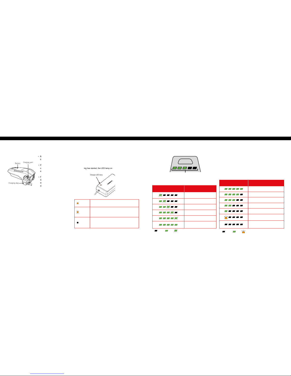
About the Battery LED Lamp
You can check the current c harging status on the LED lamp on th e battery.
Battery LED l amps
Lit up
Charging (Within 1 hour after the completion of charging)
Blinking
Charging error
Turn ed of f
Battery disconnected
(1 hour or more after th e completion of chargi ng)
About the Charger L ED Lamp
After charging has started, the LED lamp on the charger lights up.
Charger LED lamp
Battery Charging
• Bat tery can be charged in the Tazer
frame or outside of Tazer fram e.
• Pull back tab of rubberize d cover
on the back of the batte ry to
access plug inter face.
• For best charging results plu g
Shimano charger directly into a
wall outlet, then plug c harger into
side of battery.
• Both the Shimano Batter y and
Shimano Charger indicator lights
should light up, the yellow c harger
light shows it’s charging. While
the Green lights on t he battery will
blink as they are charging and be
completely solid when fully charged.
• W hen Battery is completely
charged, both it and t he charger
will turn off.
Charging plug
Battery
Charging port
<BT-E8010>
charging time for the
504 Wh Model battery
• 8 0% in 2.5 hours
• 10 0% in 5 hours
Battery level indication*1 Battery level
100% - 81%
80% - 61%
60% - 41%
40% - 21%
20% - 1%
0%
(When batter y is not installed on bic ycle)
0%, Power off / Shutd own
(When batter y is installed on bicyc le)
*1 : No light : Lit up : Blinking
(Charging-in-Progress Indication)
Page 11

20 // tazer user manual INTENSE CYCLES // 2 1
removing the battery //
A Remove battery do or by using
two ngers to compress or pull
the snap lock tab bac k toward
the door. This will allow the d oor
to pivot open so it is now angl ed
off the downtube (Ima ges #1, #2).
B Lift the door up at the a ngle it’s
at, freeing the lower l ocating tab
from the frame (Imag e #3).
C With your right han d, insert
battery key into lock .
D With your left hand, u nfold and
hold battery pu ll strap.
E Turn battery key a quarter t urn
with right hand (Imag e #4).
F Pull battery strap with left hand
until the batter y has moved past
the front lock (Imag e #5).
G Release the key. The key can
now be removed and place d in a
safe, easy to access lo cation.
H Continue pulling battery pull
strap with left han d while holding
onto the top of batter y with right
hand. The batter y will continue to
pivot off the lower mo unt and out
of the downtube (Image # 6).
I Lift the batter y out and away from
the downtube (Image #7).
installing the battery //
A Place p ull strap on batter y as
shown, then lift bat tery up with
two hands, left han d on the pull
strap and right hand at to p of
battery (Image #1).
B Angle the bottom of bat tery into the
lower mount of the downtub e and
push it into the lower mount . The
bottom of the batte ry should now be
hooked into the lower bat tery mount.
With it hooked it should n ow pivot
into the lower batter y mount as the
top of the battery i s pushed toward
the upper batter y mount (Image #2).
C Continue pushin g the top of the
battery so that it s lides into the
upper mount then clic ks and locks
into place.
D Conrm the battery has clicked
and is fully seated in the t op
battery mount by tu gging on the
battery pull str ap. If battery moves
away from the mount then pu sh it
back against mount unti l battery
is fully seated (Image # 3). The
battery pull st rap can now be
folded onto itself so i t doesn’t
obstruct the bat tery door.
E Re-instal l the battery do or
with t he lower tab tting into the
downtube opening rst (Image #4).
F Once the battery d oor fully slides
down into the door open ing, pivot
the door in a closing m otion
(Image #5) .
G As the door is nearing the closed
position at the top of th e door give
the door a good push to a llow the
door’s snap lock feat ure to engage
into the downtub e (Image #6).
6
2
2
5
7
1
3 4
4
5
3
1
6
Page 12
about the
controls
22 // tazer user manual INTENSE CYCLES // 2 3
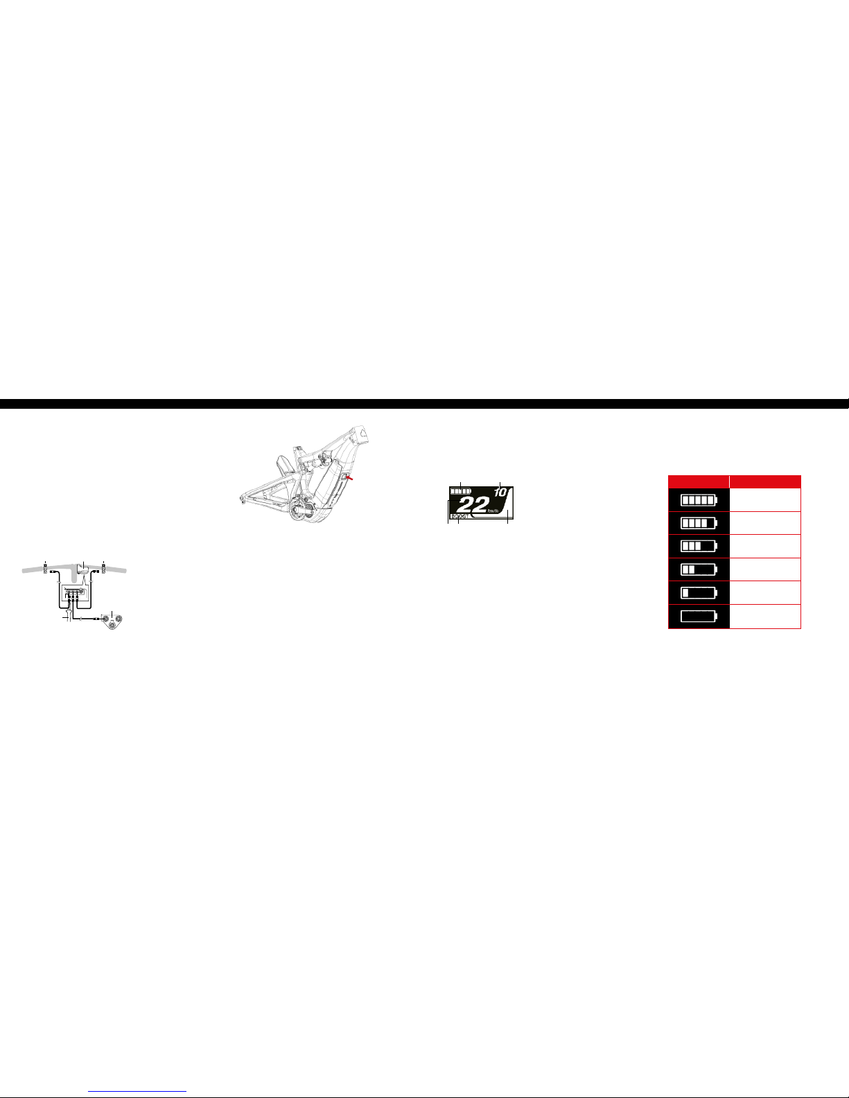
Batt er y Le ve l In di cato r
You can check the batter y level on the cycle computer while ridi ng.
dis play Battery level
81% - 100%
61% - 80%
41% - 60%
21% - 40%
1% - 20%*
0%
*The batter y level indicator bl inks red when remain ing battery
capacity fa lls to this level.
Basic Screen Display
Displays the status of t he power assisted bicycle, traveling data.
(A) (B)
(C)(D)(E)
A. Bat tery level indicator
Displays the curre nt battery level.
B. G ear position
Displays the curre ntly set gear
position. (Only displ ays when
electronic gear s hifting is in use)
C. Assist gauge
Displays the assistance.
D. Assist mode display
Displays the curre nt assist mode.
(Assist mode automat ically switches
to [ECO] as remaining bat tery
capacity dec lines. The switch to
[ECO] occurs earl ier if a battery–
powered light is connected.)
E. Current speed
Displays the curre nt speed. The
display can be switche d between
km/h and mph.
A. C ycle computer
B. Assist switch
C. S hift switch
(not spec'd for Tazer)
D. Drive unit
E. TL-EW0 2
CYCLE COMPUTER DISPLAY AND SETTING //
turning the power on/off //
cable connecting //
connecting switches and the
drive unit to the cycle computer
Turning the power ON and OF F
via the battery
• P ress the power button on the batter y. The LED lamps
will light up indicating remaining battery capacity.
NOTE:
• W hen turning on the power, check that the bat tery is
rmly attache d to the holder.
• Po wer cannot be turned on while charg ing.
• D o not place your foot on the pedals when t urning on.
A system error may result.
Automatic power off function
If the bicycle has not move d for over 10 minutes, the power
will automaticall y turn off. NOTE: the system can be forc ed
to powe r off by holdi ng down the power butt on for 6 seco nds.
(A)
(D)
(E)
(B) (C)
NOTE:
• B e sure to attach dummy plugs to any unused po rts.
• T he electric wire connecto r can be connected to any port of
the cycle computer, but we rec ommend you connect the assist
switch to the switch-side port.
Page 13
24 // tazer user manual INTENSE CYCLES // 2 5
NOTEs on walk assist mode
• I f Y is not pressed for one minute or more, th e mode active before
[WALK] mode wa s set, is re-activated.
• I f the bicycle is not moved after [WAL K] mode is activated, walk
assist is automatic ally inactivated. To re-activate [WALK ] mode,
momentarily rel ease Y and then hold down Y.
• T he walk assist function can oper ate at a maximum of 3.7 mph.
• T he assistance level and speed var y with the gear position.
• T he intelligent walk assist functio n activates when an electric shi fting
system such as XTR, D EORE XT SEIS is connected. Syste m
individually suppl ies assist power to detect gear positi on.
• " Intelligent walk assist" suppo rt rider more torque output in s teep
climb conditio n in lower side gears.
• "Q uick walk assist" function w orks by holding down SW from any mode.
BOOST
WALK
TRAIL
ECO
OFF
BOOST: Assist boost
TRAIL: Assist trail
ECO: Assist eco
OFF: Assist off
WALK: Walk assist
Changing assist mode
X1Y1
SW-E8000-L/SC-E8000
X1
Y1
SW-E6000/SC-E6010
SC-E8000
SC-E6010
Assist high
Assist normal
Assist eco
Assist off
Walk assist
: Short press Y1
BOOST
WALK
TRAIL
: Short press X
Changing assist mode
X1Y1
SW-E8000-L/SC-E8000
X1
Y1
SW-E6000/SC-E6010
SC-E8000
SC-E6010
Assist high
Assist normal
Assist eco
Assist off
Walk assist
: Short press Y1
: Short press X1
BOOST
WALK
TRAIL
ECO
: Short press Y
Changing assist mode
X1Y1
SW-E8000-L/SC-E8000
X1
Y1
SW-E6000/SC-E6010
SC-E8000
SC-E6010
Assist high
Assist normal
Assist eco
Assist off
Walk assist
: Short press Y1
: Short press X1
: Long press Y1
BOOST
WALK
TRAIL
ECO
: Long press Y
Changing assist mode
X1Y1
SW-E8000-L/SC-E8000
X1
Y1
SW-E6000/SC-E6010
SC-E8000
SC-E6010
Assist high
Assist normal
Assist eco
Assist off
Walk assist
: Short press Y1
: Short press X1
: Long press Y1
: Short press X1 (This operation is for canceling
BOOST
WALK
TRAIL
ECO
: Short press X
(This operation i s for canc eling [WALK] mode)
*The Walk assis t mode function may n ot
be able to be used in c ertain region s.
(SC-E8000)
X
Y
(SW-E6000-L / SC-E8000)
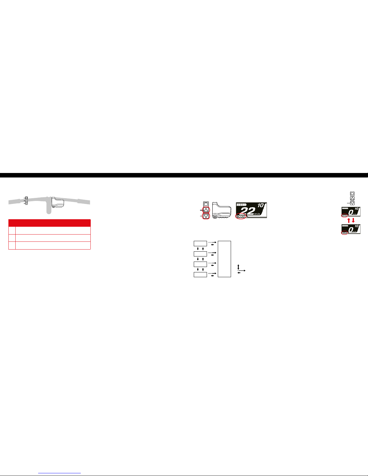
assist modes
To help maximize battery p erformanc e and efficie ncy, select an
appropriate as sist mode for your spec ic application.
Changing assist mode
Press X or Y to switch assi st modes.
switching to walk assist mode
1. With your feet off t he pedals and current speed
at [0 mph], hold down Y until [ WALK] displays.
NOTE: A warning tone wi ll sound while switching
is in progress if it is n ot possible to switch to
[WALK] mode b ecause the current speed is not
[0 mph] or there is pressu re on the pedals etc.
2. Release Y when (WALK) displays.
3. Hol d down Y again to activate walk assist. Walk
assist remains acti ve provided Y is being held down.
4. To cancel ( WALK) mode, release Y and press X .
When (WALK) mod e is canceled, the mode active
before (WALK) mo de was set, is re-activated.
YX
Y
B O O S T //
Use when powerf ul assistance is required, suc h as when riding up
steep uphill slopes. T his mode is designed for use on ste ep inclines
and precipitous mo untains. When riding on level publi c roads with
trafc lig hts, the assistance pr ovided may be excessive, in which
case, switch to [ECO] mod e.
t r a i l //
Use when an intermedi ate level of assistance is needed, such as
when you want to enjoy ridin g comfortab ly on a gentle slope or
level ground.
eco //
Use when you want to enjoy long d istance riding on level ground.
When pedaling is not ver y strong, the amou nt of assistance is
reduced and energy consumption is lessened.
walk //
This mode is part icularly useful when walking the bicyc le, taking
the bicycle out up an inc line or when it is bear ing a heavy load.
It is also useful when wal king the bicycle ac ross uneven terrain
such as rocky area s.
assist and shift switches //
X
Y
A
SW-E6000-L
X Switchi ng assist modes: the level of assi stance becomes stron ger
Y Switching assi st modes: the level of assistanc e becomes weaker
A Changing the cycle computer display
Page 14

26 // tazer user manual INTENSE CYCLES // 2 7
maintenance
maintenance SchedulE* //
Action Every Ride
500 Miles or
1 Month
2000 Miles or 6
Months
4000 Miles o r
1 Year
Tires
Check air pres sure, inspect tread an d sidewalls for tears a nd
punctures
X
Chain
Brush off and l ubricate X
Brakes
Squeeze brakes and conrm function X
General
Clean comple te bike of mud and debris X
Headset
Check adjustment X
Box Link
Add grease thru zerk ttings X
Frame Pivots
Check torques X
Spokes
Inspect for damage, check tension X
Shock and Fo rk
Check air pres sure, inspect for leak s X
Deraileur Cables
Inspect and lub e X
Seatpo st
Clean and regre ase interface wit h frame X
Frame Pivots
Remove pivot bolts, check bearings for pitting and wear X
Headset
Disassemble stem, headset and fork. Check bearings for
pitting and wear
X
Hubs
Pull wheels of f, check hub bearings f or pitting and wear X
Bottom Bracket
Remove crank arm s and check BB bearin gs for pitting and
wear
X
Brakes
Replace brake pads X
Chain
Inspect for damage and check for stretching X
General
Complete Tune-Up X
Shock and Fo rk
Overhaul See MFG Recommendations
general service and care //
You have purchased a high performance bicycle
which requires a ce rtain level of ser vice and
maintenance to sustain the level of performance
your frame was designe d around. Proper care will
also ensure the bike is safe t o ride at all levels. It
is important to re ad and understand t he carbon
care information as well as follow the maintenance
schedule and inspec t your bicycle before each ride.
These will not only hel p to limit or avoid costly
repairs but will als o help to avoid injury du e to
service neglect and component failure.
carbon care //
Intense Cycles empl oys advanced compo site techniques and ma terials
in our frames which d o require a cert ain level of care and mainten ance
to ensure a safe experie nce at the high level of performanc e each frame
is designed around. N ot following these guideline s will decrease the level
of performanc e and possibly cause injury or de ath.
• U se a soft cloth with warm soapy water to c lean the carbon surface s.
Do not use high pressur e washers, abrasive cloths or clea ners.
• B e sure all frame surfaces in co ntact with cables are protecte d.
Cable housing rubb ing on carbon can wear over time.
• B e sure brake levers, handle bar ends and the fo rk crown do not
contact the fram e at full rotation.
• N ever clamp any part of a carbon fram e in a bike stand or car rack.
• A lways inspect your frame if you experi ence any chain suck.
• A lways inspect your frame in full af ter a crash to be sure there is
no damage. Look for cra cks, dents or loose bers. If you disc over
damage in any degree it ’s best to have your frame inspected by a
qualied Intense Cyc les dealer. Any direct impact to the frame c an
cause serious structural damage.
• U se high grade waterproof grease on se at post, BB and head set
bearing contac t areas with the carbon.
• N ever ream or face a carbon frame.
• B e sure to follow all recommended tor que settings.
• Use only genuine replacement par ts for safety-critical components.
* The above mainten ance schedule is on ly a guideline. Refer to c omponent manufa ctuter for speci c instruction o n maintaining thei r parts.
Page 15

28 // tazer user manual INTENS E CYCLES // 2 9
Error indication t ype Indication condition
Lighting patter n *1
Recovery
System error
Communicati on error with
the bicycle system
Make sure that the ca ble is not loose or improp erly connected. If the
situation does n ot improve, contact the pla ce of purchase.
Temperature
protection
If the temperatur e exceeds
the guaranteed operating
range, the batte ry output
is turned off.
Leave the batter y in a cool place away from dir ect sunlight until the
internal temper ature of the battery dec reases sufcient ly. If the situation
does not improve, co ntact the place of purch ase.
Security
authentication
error
This is displayed if a
genuine drive uni t is not
connected.
This is displayed if
any of the cables are
disconnected.
Connect a genui ne battery and drive uni t.
Check the cond ition of the cables.
If the situation d oes not improve, contact t he place of purchase.
Charging error
This is displayed if a n error
occurs during charging.
Remove the charger f rom the battery and pr ess the power button. If an
error appears contact an agency.
Battery malfunction
Electrical failure inside
the battery
Connect the ch arger to the battery an d then remove the charger. Press
the power button w ith only the battery c onnected.
If an error appea rs with only the batt ery connected , contact the plac e of purchase.
*1 : No light : Lighting up : Blinking
Code Display preconditions
Operational r estriction when a n error is being disp layed
Remedy
W010
Temperature of the drive u nit
is higher than it is d uring times
of normal operation.
Power assistance may be lower than usual.
Stop using the ass ist function until the te mperature of the
drive unit drops. I f the situation does not imp rove, contact
the place of purc hase.
W011
The traveling spe ed cannot be
detected.
The maximum spe ed up to which power
assistance is p rovided may be lower than
usual.
Check that the spe ed sensor is properly i nstalled. If the
situation does n ot improve, contact the pla ce of purchase.
W013
Initializati on of torque
sensor was not com pleted
successfully.
Power assistance may be lower than usual.
With your foot of f the pedal, press the bat tery power
button and turn o n the power again. If the situa tion does
not improve, conta ct the place of purchase.
W032
An electroni c derailleur may
have been installe d in place of
a mechanical derailleur.
Power assistanc e provided in [WALK] m ode
may be lower than usual.
The walk assist mo de function may not be
able to be used in cer tain regions.
Reinstall the der ailleur for which the syst em is congured
to support. If t he situation does not imp rove, contact the
place of purchas e.
Warning Messages on the Cycle Computer
This disappear s if the error is xed.
TROUBLESHOOTING //
Battery LED Lamp Error Indications
System errors and similar warnings are indicated by the battery LED lamps through various lighting patterns.
Reference //
Shimano Steps E8000 User Manual: ht tp://si.shimano.com /pdfs/um/UM-72F0A-006-00 -ENG.pdf
Page 16

INTENSE CYCLES // 3 1 30 // This declaration of conformity is specic to countries following CE marking directives.
INTENSE TAZER MANuAL //
Declaration of Conformity
Hereby confirm s the following p roducts:
Product Name: INTENSE TAZER e-Bike
Year of Construction: 2018 / 2019
Conformity with all applicable provisions from
the Machiner y Directive (2006/42 /EC).
The machine confo rms to all applicable provisions of th e
Directive 2014/30/EU Electromagnetic Compatibility Directive.
These standa rds were applied:
EN 15194 / 2017 Bicycles:
Electrically power assisted bicycles, EPAC Bicycles.
ISO 4210-2 Bicycles: Safety requirements for bicycles.
Technical documentation from:
INTENSE CYCLES
42380 Rio Nedo
Temecula, CA 92590- 3708, USA
TEL: 1.951.296.9596
Place and Date of i ssue of this
Declaration of Conformity:
Temecula, CA, August 15, 2018.
Jeff Steber
CEO/ Founder
Chad Peterson
COO/ Product Manager
Chris Knutson
Engineer
The Manufacturer
INTENSE CYCLES
42380 Rio Nedo
Temecula, CA 92590- 3708, USA
TEL: 1.951.296.9596
Tazer intende d for Offroad Use .
Page 17

P h o n e :
+1(951)-307-9211
Customer Service:
techcenter@intensecycles.com
General Info:
info@intensecycles.com
Media, Marketing, Sponsorship:
marketing@intensecycles.com
Intense Cycles USA 42380 rio nedo Temecula, Ca. 92590
www.INTENSeCYCLES.com
330026
 Loading...