

user manual
Sniper XC
Sniper Trail
AT INTENSE, WE HAVE ONE GOAL - TO PROVIDE THE RIDE OF YOUR LIFE //
Our team of designers, engineers and product experts are focused on one thing every
day: your experience on the bike. We build bikes that are as thrilling to look at as they
are to ride, and we build them for the select few of you who understand the difference
and refuse to settle for anything else.
From the early days of Intense, when founder Jeff Steber worked alone in his garage to
today, where a crew of talented people work in a Temecula, CA factory, Intense has been
a brand built on passion by forward thinkers who, even today, love nothing more than
to throw a leg over a sweet bike and head out for a rip. We’re so glad you’ve joined us.
Welcome to Intense, enjoy your experience.
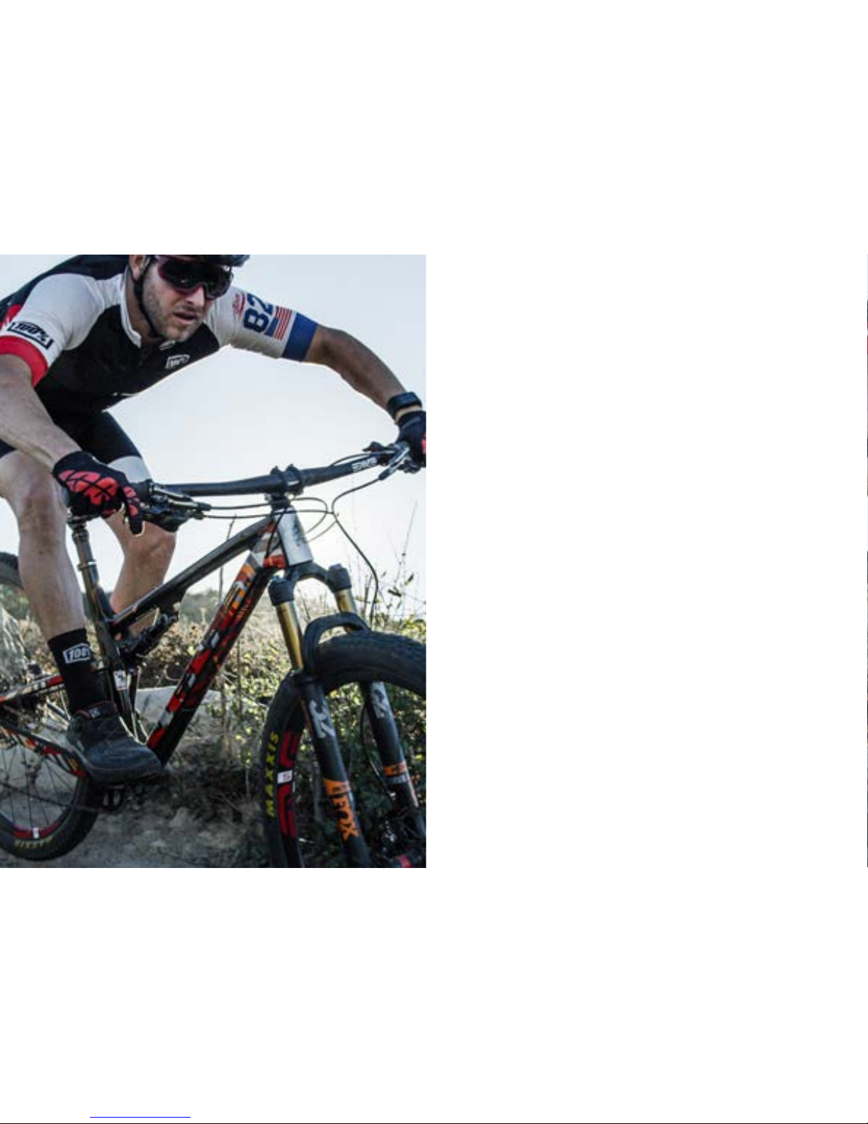
THE SNIPER XC, SNIPER TRAIL //
The Sniper is a ground-up, dedicated, pedaling machine with two different travel
versions, XC 100mm and Trail 120mm. Short travel rigs should descend like their long
travel siblings and that’s what we’ve done. This is no “Twitchy XC bike”. With the 29”
wheel size and progressive XC/Trail geometry, you get a stable ride that goes where you
point it. Offered with a standard hardware package as well as a light weight SL package
to shave some grams, the Sniper takes XC Race and Trail riding to the next level.
registration
WWW.INTENSECYCLES.COM/WARRANTY-CARD/
contact customer service
cs@intensecycles.com
951-296-9596
Welcome to
the family
2 // SNIPER user manual
introduction / registration 2
Sniper xc frame features / component spec 4
sniper xc Geometry 5
sniper trail frame features / Component spec 6
sniper trail geometry 7
exploded view and b.o.m. 8
Assembly 10
torque chart 17
setup 18
maintenance 22
INTENSE CYCLES // 3

4 // SNIPER user manual
sNIPer xc
frame
features /
spec
Frame Features //
• Rear Travel: 3.94 inches (100mm) with 165 x 40 stroke shock
• 29” Wheel size
• Integrated BOOST 148 x 12 dropouts
• 4.76 lbs / 2158 grams = Standard frame w/ alloy lower link & shock
• 4.73 lbs / 2144 grams = SL Super Light frame w/ magnesium lower link & shock
• Injection molded top link
• INTERNAL CABLE ROUTING
• Internal Seat Tube Cable Routing for dropper posts
• Monocoque front triangle
• H20 Bottle Fitment
• FLacK GuaRD Downtube, Chainstay, and Seatstay protection
• Tapered Head Tube
• Max Bearings and Dedicated Frame Hardware
Component Spec //
• Fork: FOX 32 Step Cast 100mm with 44 mm Offset, 503.7mm Axle to crown length
• Rear Shock: FOX Float DPS 165 x 40, trunnion mount, 20mm x 8mm reducers
• Seat post – 31.6mm
• Headset – Cane Creek, 40, Alloy Cartridge (www.canecreek.com) IS 41 Top, IS
52 Lower. IS=Integrated Top and Lower Headset
• Bottom bracket - PF92
• Rear Axle – BOOST 148 x 12 with hidden lever
• Brake Mount – Post Mount for 160mm rotor
• Crank set - BOOST 148 Compatible - single ring only
• Rear Wheel - BOOST 148 Compatible

INTENSE CYCLES // 5
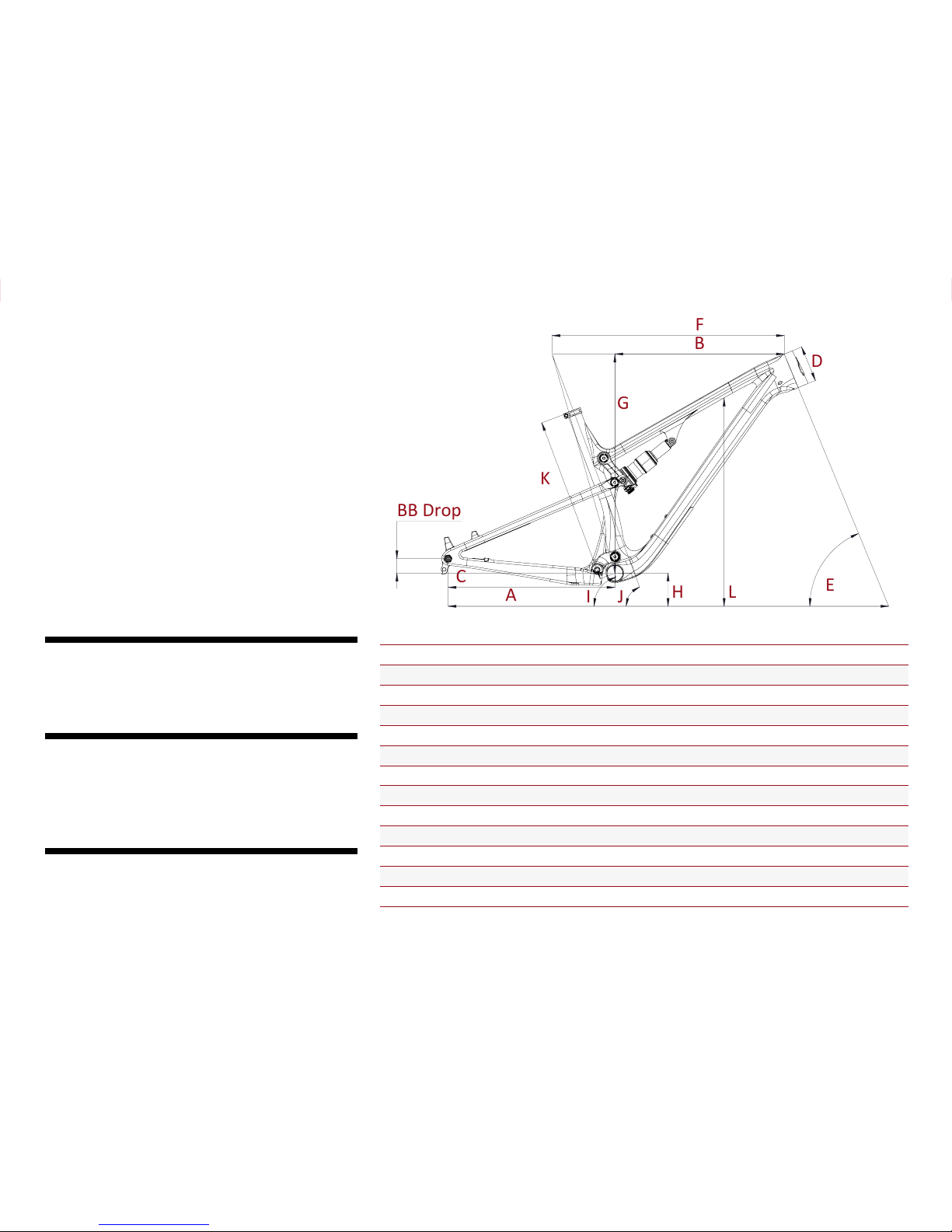
sNiPer xc
Geometry
BB Drop
C
F
A
B
E
D
G
H
L
K
I
J
GEOMETRY NOTEs
GEOMETRY TAKEN AT TOP OUT WITH 503.7MM axle to crown length
AND 44mm FORK OFFSET.
Component spec NOTE
the sniper xc is designe d around the use of a s ingle chain ring
only. Use of a double or triple ring set will not allow prop er
clearance with the frame.
Warning
NOT INTENDED FOR USE WITH FORKS LARGER THAN 120MM OF TRAVEL.
SMALL MEDIUM LARGE XLARGE
A Wheel Base: 1127 mm / 44.4” 1152 mm / 45.37” 1179 mm / 46.4” 1206 mm / 47.5”
B Top Tube Length: 584 mm / 23.0” 609 mm / 24.0” 635 mm / 25” 660 mm / 26”
C Chain Stay Length: 439 mm / 17.3” 439 mm / 17.3” 439 mm / 17.3” 439 mm / 17.3”
D Head Tube Length: 90 mm / 3.54” 95 mm / 3.7” 105 m m / 4.13” 115 mm / 4.5”
E Head Tube Angle: 67. 5 ˚ 67. 5 ˚ 67.5˚ 67. 5 ˚
F Reach: 421 mm / 16.6” 444.5 mm / 17.5” 468 mm / 18.4” 490 mm / 19.3”
G Stack: 570 mm / 22.45” 575 mm / 22.6” 584 mm / 23” 593 mm / 23.4”
H BB Height: 330 mm / 13.0” 330 mm / 13.0” 330 mm / 13.0” 330 m m / 13.0”
BB Drop: 38 mm / 1.50” 38 mm / 1.50” 38 mm / 1.50” 38 mm / 1.50”
I Seat Tube Angle (Effective): 74˚ 74˚ 74˚ 74˚
J Seat Tube Angle (Actual): 6 9.4˚ 69.4˚ 69.4˚ 69.4˚
K Seat Tube Length: 406 mm / 16” 437 mm / 17.2” 488 mm / 19.2” 538 mm / 21.2”
L Standover Height: 769 mm / 30.3” 771 mm / 30.4” 776 mm / 30.5” 781 mm / 30.75”

6 // SNIPER user manual
Frame Features //
• Trail Rear Travel: 4.7 inches (120mm) with 165 x 45 stroke shock
• 29” Wheel size
• Integrated BOOST 148 x 12 dropouts
• 4.76 lbs / 2158 grams = Standard frame w/ alloy lower link and shock
• 4.73 lbs / 2144 grams = SL Super Light frame w/ magnesium lower link & shock
• Injection molded top link
• INTERNAL CABLE ROUTING
• Internal Seat Tube Cable Routing for dropper posts
• Monocoque front triangle
• H20 Bottle Fitment
• FLacK GuarD Downtube, Chainstay, and Seatstay protection
• Tapered Head Tube
• Max Bearings and Dedicated Frame Hardware
Component Spec //
• Fork: FOX 34 120 mm with 51 mm Offset, 527.1mm axle to crown length
• Rear Shock: FOX Float DPS 165 x 45, trunnion mount, 20mm x 8mm reducers
• Seat post – 31.6mm
• Headset – Cane Creek, 40, Alloy Cartridge (www.canecreek.com) IS 41 Top, IS
52 Lower. Is = Integrated Top and Lower Headset
• Bottom bracket - PF92
• Rear Axle – BOOST 148 x 12 with hidden lever
• Brake Mount – Post Mount for 160mm rotor
• Crank set - BOOST 148 Compatible - single ring only
• Rear Wheel - BOOST 148 Compatible
sNIPer trail
frame
features /
spec
INTENSE CYCLES // 7
GEOMETRY NOTEs
GEOMETRY TAKEN AT TOP OUT WITH 527.1MM axle to crown LENGTH
AND 51MM FORK OFFSET.
Component spec NOTE
the sniper trail is designed around the use of a single chain
ring only. Use of a double or triple ring set will not allow
proper clearance with the frame.
Warning
NOT INTENDED FOR USE WITH FORKS LARGER THAN 120MM OF TRAVEL.
sNIPer trail
Geometry
BB Drop
C
F
A
B
E
D
G
H
L
K
I
J
SMALL MEDIUM LARGE XLARGE
A Wheel Base: 1142 mm / 45” 1168 mm / 46” 1195 mm / 47” 1221 mm / 48”
B Top Tube Length: 584 mm / 23.0” 609 mm / 24.0” 635 mm / 25” 660 mm / 26”
C Chain Stay Length: 439 mm / 17.3” 439 mm / 17.3” 439 mm / 17.3” 439 mm / 17.3”
D Head Tube Length: 90 mm / 3.54” 95 mm / 3.7” 105 mm / 4.13” 115 mm / 4.5”
E Head Tube Angle: 66.5˚ 66.5˚ 66.5˚ 66.5˚
F Reach: 421 mm / 16.6” 444.5 mm / 17.5” 468 mm / 18.4” 490 mm / 19.3”
G Stack: 570 mm / 22.45” 575 mm / 22.6” 584 mm / 23” 593 mm / 23.4”
H BB Height: 338 mm / 13.3” 338 mm / 13.3” 338 mm / 13.3” 330 mm / 13.0”
BB Drop 38 mm / 1.50” 38 m m / 1.50” 38 mm / 1.50” 38 mm / 1.50”
I Seat Tube Angle (Effective): 73˚ 73˚ 73˚ 73˚
J Seat Tube Angle (Actual): 68 .4˚ 68.4˚ 68 .4˚ 68.4˚
K Seat Tube Length: 406 mm / 16” 437 mm / 17.2” 488 mm / 19.2” 538 mm / 21.2”
L Standover Height: 779 mm / 30.7” 781 mm / 30.76” 786 mm / 31” 791 m m / 31.2”
8 // SNIPER user manual
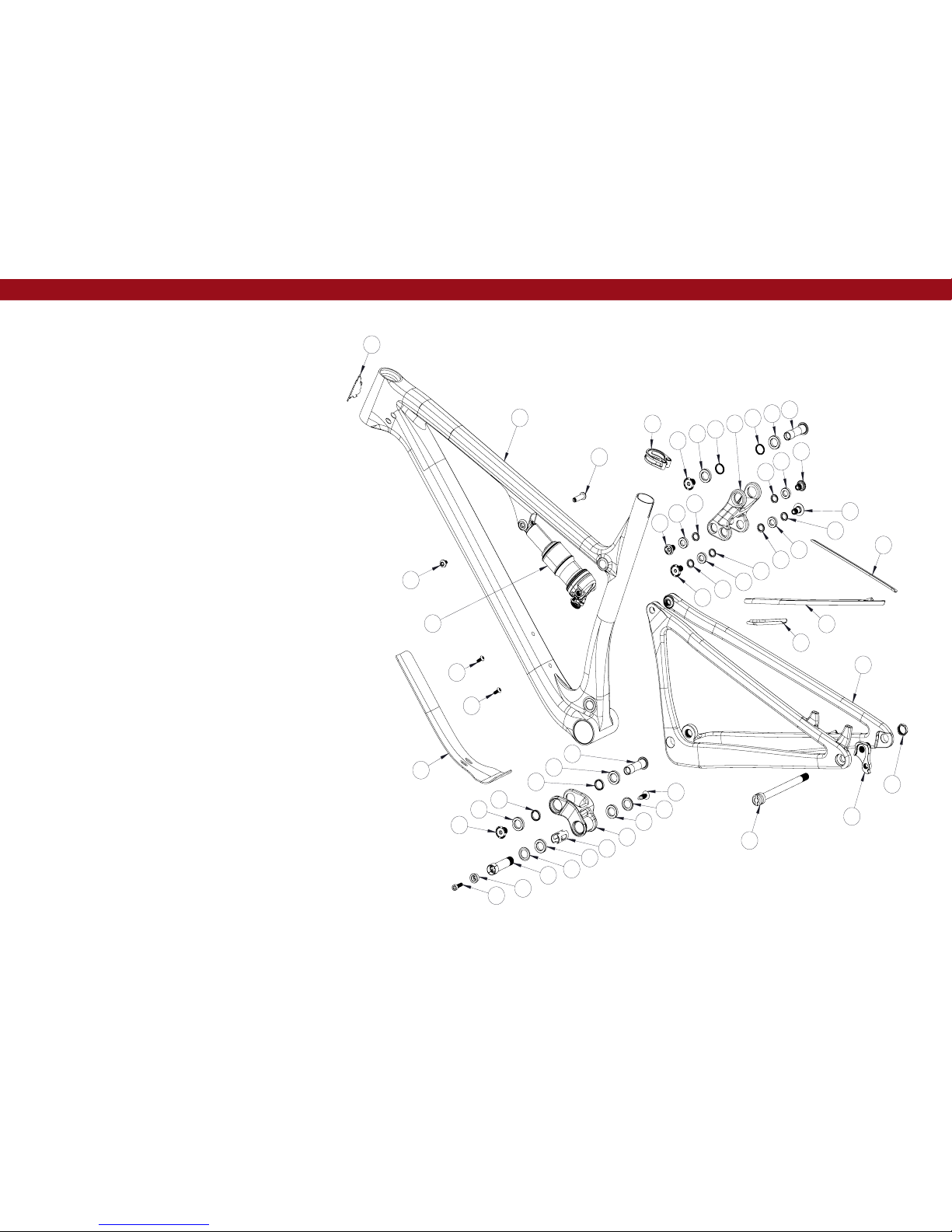
exploded
view and
b.o.m.
29
30
22
12
7
11
9
4
24
8
6
5
15
32
17
1
10
16
23
2
3
19
20
21
1
23
23
7
10
8
11
13
11
13
11
24
11
9
23
11
24
12
24
23
19
23
31
14
26
25
27
18
28

INTENSE CYCLES // 9
ITEM
NO.
ITEM
PART
NUMBER
DESCRIPTION QTY. TORQUE SPEC.
1
Bearing Cap 130765 Top Link Bearing Cap 2 N /A
2
Bolt Main Pivot 130791
Bolt Main Pivot
1.5t Expan der Blk
1
7 Nm /
60 in-lbs
3
Cone Adjuster 130807 Main Pivot Expander Cone 1 N/A
4
Top Lin k 130823 Injection Molded Top Link 1 N /A
5
Hanger 130826 Forged Derailleur Hanger 1 N/A
6
Hanger Nut 130827 Rear Derailleur Hanger Nut 1
11 Nm /
100 in-lbs
7
Axle Upper 130828 Top Link Pivot Axle 2
12 Nm /
106 in-lbs
8
Bolt Shoulder 130829 Top Link Upper Pivot Bolt 2
12 Nm /
106 in-lbs
9
Spacer 130830
Top Link Upper Spacer,
19mm OD 15m m ID 2.5mm
2 N /A
10
Spacer 130831
Lower Lin k Spacer
19mm OD x 15m m ID x 4mm
2 N /A
11
Spacer 130832
Top Link Lower Spacer
15mm OD x 10mm ID x 2.5mm
6 N /A
12
Shock Bolt 130833 Trunnion Shock Bolt 2
16 Nm /
140 i n-l bs
13
Bolt Shoulder 130834 Top Link Lower Pivot Bolt 2
16 Nm /
140 i n-l bs
14
Bearing Spacer 130845 Lower Link Bearing Spacer 1 N/A
15
Rear Axle 130846
148 x 12mm Boost
with Hidden Lever
1
11 Nm /
100 in-lbs
16
Lower Link 130825 Forged Aluminum Lower Link 1 N/A
16
Lower Link 130854 Forged Magnesium Lower Link 1 N/A
17
Plug 140038 Lower Link Pivot Plug 1 N/A
ITEM
NO.
ITEM
PART
NUMBER
DESCRIPTION QTY. TORQUE SPEC.
18
Seat Collar 340343 Bolt-On Seat Clam p 1
4 Nm /
35.5 in-lbs
19
BHCS
M5 X 12
410010
Bottle Mount Bolt,
Button Head, M5 X 12
2
6 Nm /
54 in-lbs
20
SHCS
M6 x 22
410009
Cone Adjuster Bolt,
Socket Head, M6 x 22
1
14 Nm /
125 in-lbs
20
SHCS
M6 x 22
41003 2
Cone Adjuster Bolt,
Socket Head, M6 x 22 Titanium
1
14 Nm /
125 in-lbs
21
Shock Bolt,
Male
410056 M6 Th read, Steel 1
10 Nm /
88 in-lbs
21
Shock Bolt,
Male
410066 M6 Thread, 7075-T6 1
10 Nm /
88 in-lbs
22
Shock Bolt,
Fema le
410060
8mm OD x 31mm
Long Female Steel
1
10 Nm /
88 in-lbs
22
Shock Bolt,
Fema le
410067
8mm OD x 31mm
Long Female 7075-T6
1
10 Nm /
88 in-lbs
23
Bearing 6802 430008
15 x 24 x 5 2RS,
MAX Radia l Bearing
6 N /A
24
Bearing 6800 430011
10 x 19 x 5 2RS,
MAX Radia l Bearing
4 N/A
25
Guard Fla ck CS 500294 Flack Guard Sniper Chainstay Top 1 N /A
26
Guard Fla ck Ststy 500295 Flack Guard Sniper Seatstay 1 N/A
27
Guard Fla ck CS 500296
Flack Guard Snipe r
Chainstay Bottom
1 N/A
28
Guard Fla ck DT 500297 Flack Guard Sniper Downtube 1 N/A
29
Head Badge 500335 Head Badge Flame Logo 1 N/A
30
Rear Shock Shock 165 x 40 XC, 165 x 45 Trail 1 N/A
31
Front Triangle Carbon, 4 Sizes 1 N/A
32
Rear Triangle Carbon, 1 Size 1 N/A
(ST)
(ST)
(ST)
(ST)
(SL)
(SL)
(SL)
(SL)

10 // SNIPER user manual
Assembly
Tools needed
• HIGH GRADE WATERPROOF GREASE
• 5MM HEX WRENCH
• 6MM HEX WRENCH
• 8MM HEX WRENCH
• TORQUE WRENCH
• 5MM HEX BIT
• 8MM HEX BIT
• 19MM SOCKET
pro tips
• BE SURE TO APPLY A THIN COAT OF GREASE TO ALL PIVOT AXLES AND REAR AXLE.
THIS WILL REDUCE THE CHANCES OF CORROSION DUE TO MOISTURE AND PREVENT ANY
POSSIBLE CREAKS.
• AFTER THE FIRST FEW RIDES AND ALL THE COMPONENTS ARE BROKEN IN AND SETTLED
INTO PLACE, GO THROUGH AND RE TORQUE ALL PIVOT AXLES AND FASTENERS. AFTER
THIS FIRST ADJUSTMENT, YOU WILL BE READY TO RIP FOR THE LONG HAUL.
• USE GREASE ON ANY METAL TO CARBON INTERFACE, INCLUDING BB AND HEADSET.
PREFACE //
Service and maintenance on an Intense bicycle requires special tools, abilities and
knowledge of working on bicycles. It is always recommended to use an authorized
Intense dealer for service and maintenance. Always wear eye protection. It is critical
to use the proper tools, loctite, grease and torque specs during assembly. Failure to
follow these instructions may result in serious bodily injury or death.

INTENSE CYCLES // 1 1
1
53
642
CONNECTING TOP LINK TO FRONT TRIANGLE //
A Holding top link (#130823) as oriented
in the above picture; hold upper link
pivot bolt spacers (#130830) with your
fingertips against the inside of the bearing
races (IMAGE #1).
B Match upper link to pivot point on top
tube making sure the spacers don’t fall out.
C Using upper pivot axle (#130828), insert
through non-drive side of top link bearing
and push through to drive side bearing
(IM AGE #2).
D Thread shoulder bolt (#130829) by
hand until snug. We will return with a
6mm hex key and a 5mm hex key bit on
a torque wrench after completed frame
assembly.
CONNECTING THE LOWER LINK TO FRONT TRIANGLE //
A Holding the lower link (#130854), use
a small dab of grease on the lower link
spacers (#130831) to help keep them
against the inside of the bearing races
for easier installation (IMAGE #3).
B From the back of the seat tube, slide
the lower link over and match lower link
to pivot point on front triangle, making
sure the spacers don’t fall out (IMAGE #4).
C Using the pivot axle (#130828), insert
through drive side of lower link bearing
and push through to drive side bearing
(IMAGE #5).
D Thread shoulder bolt (#130829) by
hand until snug. We will return with a
6mm hex key and 5mm hex bit on a
torque wrench after completed frame
assembly (IMAGE #6).

12 // SNIPER user manual
8
7
11 139
12 1410
CONNECTING REAR TRIANGLE TO LOWER LINK //
A Put a small dab of grease on the
outside bearing race as well as on
the contacting surface of the bearing
cap (#130765). This will help hold the
bearing caps in place during installation
(IMAGE #7).
B Slide rear triangle over the lower link
and line up the pivot point over the
bearing caps (IMAGE #8).
C Insert greased main pivot bolt
(#130791) into non-drive side of lower
link. Insert 8mm hex wrench and tighten
till lightly snug. We will return with a
torque wrench after completed frame
assembly (IMAGE #9).
D Insert push rivet (#140038) on the
drive side in the pivot axle (IMAGE #10).
CONNECTING REAR TRIANGLE TO TOP LINK //
A Put a small dab of grease on the
outside/inside bearing races as well as
on the contacting surface of the bearing
spacers (#130832). Be sure to place a
greased bearing spacer on both the
outside and inside bearing faces. You
will use a total of 4 spacers for this
step (IMAGE #11 and #12).
B Swing the rear triangle up to line up
pivot point with upper link bearing cap
(IMAGE #13).
C Insert clevis bolts (#130834) into
drive side and non-drive side seat stays.
Tighten by hand until snug. We will come
back with 5mm hex torque wrench after
complete frame assembly (IMAGE #14).

INTENSE CYCLES // 1 3
INSTALLING REAR SHOCK //
A Holding the shock with the shaft and
eyelet pointing towards the front of the
bike, align shock eyelet with shock tab.
Insert shock shoulder bolt (#410067) from
non-drive side and thread in shock shoulder
bolt (#410066) on drive side (IMAGE #15).
Tighten until snug by hand and we will
return with a 5mm hex key and torque
wrench after completed frame assembly.
B Put a small dab of grease on the bearing
spacer (#130832) and place on inside
facing bearing race. You will be using 2
bearing spacers for this step. Then gently
pivot shock trunnion mount tabs into place
and align (IMAGE #16 and #17).
C Insert and thread in trunnion bolt
(#130833) on drive side and non-drive
side and tighten by hand until snug. We
will return with a 5mm hex key torque
wrench after completed frame assembly
(IMAGE #18).
17 2015
19
18 2116
INSTALLING DERAILLEUR HANGER //
A Apply a thin layer of grease to the
derailleur hanger (#130826) shank and
install into the keyed insert on the drive
side of the rear triangle (IMAGE #19).
B Install derailleur hanger nut (#130827)
using a 19mm socket, torque to 11 nm /
100 in-lbs (IMAGE #20 and #21).

14 // SNIPER user manual
TOP LINK TORQUE PROCEDURE //
A First step here is to tighten the top link
pivot axle (#130828 & #130829). Using
a 6mm hex wrench and a 5mm hex bit
on a torque wrench, tighten to 12 nm /
106 in-lbs (IMAGE #24).
B Next we will tighten the clevis bolt
(#130834). Using a 5mm hex bit on a
torque wrench, tighten to 16 nm / 140
in-lbs (IMAGE #25).
22 2423 25
SHOCK TORQUE PROCEDURE //
A Using a 5mm hex key and a 5mm hex
bit on a torque wrench, tighten shock
bolt (#410066 &410067) to 10 nm /
88 in-lbs (IMAGE #22).
B Using a 5mm hex bit on a torque
wrench, tighten trunnion bolts (#130833)
to 16 nm / 140 in-lbs (IMAGE #23).

INTENSE CYCLES // 1 5
27
26 29
28
LOWER LINK TORQUE PROCEDURE PT.1 //
A Using a 8mm hex bit on a torque
wrench, tighten main pivot bolt (#130791)
to 7 nm / 60 in-lbs (IMAGE #26).
B Next install the cone spacer (#130807)
with the M6x22mm bolt (#410032) and
tighten until snug by hand (IMAGE #27).
C Using a 5mm hex bit on a torque
wrench, tighten to 14 nm / 125 in-lbs
(IMAGE #28).
LOWER LINK TORQUE PROCEDURE PT.2 //
A Using a 6mm hex wrench and a 5mm hex bit on a torque wrench, tighten the pivot axle
& shoulder bolt (#130828 & #130829) to 12 nm / 106 in-lbs (IMAGE #29).

16 // SNIPER user manual
31
30 33 34
32
REAR AXLE ASSEMBLY //
A Insert QR 148x12mm rear axle
(#130846) into axle opening on non-drive
side (IMAGE #30).
B Align and start the axle thread. (IMAGE
#31) then, grab the tips of the silver bar
going through the rear axle, pull out and
push over to one side (IMAGE #32).
C Tighten axle using the integrated lever
to approximately 10 nm.
D Tip lever back over until parallel with axle and push back in until flush (IMAGE #33
an d #34) .

INTENSE CYCLES // 1 7
torque
Achieving proper torque is vital to
ensuring the safe performance and
function of the SNIPER frame. Failure
to do so could result in sub-optimal
performance of your fra me as well as
premature wear and tear of individual
parts.
additional reference
In addition to this chart, all torque
values are laser etched onto
corresponding hardware for your
reference.
torque chart
12 Nm / 106 in/lbs
4 Nm / 35.5 in/lbs
16 Nm / 140 in/lbs
16 Nm / 140 in/lbs
12 Nm / 106 in/lbs
10 Nm / 88 in/lbs
M8 HEX 7 Nm / 60 in/lbs
M5 HEX 14 Nm / 125 in/lbs
Derailleur Cap: 11 Nm / 100 in/lbs
Axle (non-drive side): 10 Nm / 88 in/lbs

seatpost
Before insertion, liberally coat the seat post with carbon paste and gently slide
into the seat tube. With a minimum seat post insertion of 4", tighten seat post
clamp to 4nm. (Over tightening the seat post clamp will inhibit the movement of
the seat post and potentially damage seat post and/or seat tube.
18 // SNIPER user manual
set up
4”
seatpost
PREFACE //
We are almost ready to rip. Just a few
more checkpoints and adjustments
to ensure the performance and ride
characteristics of the Sniper is optimised
for you.
Tools needed
• shock pump
• small ruler or measuring device
• Intense Carbon Paste
• TORQUE WRENCH
recommendation
When setting up the suspension sag, ask a fellow ripper to help. but if alone,
using a wall to lean your shoulder against will do just fine.

INTENSE CYCLES // 1 9
setting the sag
1. Remove fork and shock air caps and be sure you have a shock
pump and a small ruler or measuring device handy.
2. Go ahead and hop on the bike. Be sure to place all your weight on the
seat with the dropper in the up position and both hands on the grips.
3. Give the bike 5-6 moderate bounces and sit back down on the saddle.
4. Now have your friend slide both the rear shock and the front fork
o-rings down against the seal lip of the damper bodys (IMAGE #1).
5. Step off the bike nice and easy. Be sure to not compress the suspension
after the o-rings have been set.
Pro Tip
Here is where having a friend helps. Have them straddle the front wheel and pull
the handle bars in a upward direction as to not allow the suspension to compress
as you get off (image #4).
6. Using your measuring device, measure the gap between the suspension
seal lip and the o-ring. Using the chart on the following page will tell you
if you need more air pressure or less air pressure (IMAGES #2, #3).
7. Adjust air pressure with your shock pump accordingly (IMAGE #5).
8. Re-visit steps 2-6 until your desired sag measurement have been reached.
9. Install valve caps.
10. Go ride your bike!
15% - 25%
While suspension
is comp ressed on
fork or rea r shock,
slide o-ring down
against the seal lip
of damper body.
Release compression.
Measure gap from
o-ring to seal lip.
Sniper XC = 12mm
Sniper Trail = 13.5mm
4
21
3 5
cm 1 2 3 4 5 6 7 8 9 10

Snipe r XC
Trav el
100mm
Shock StRoke
40mm
Shock Sag
30% when sitting on the bike
Fork Sag
15-25% when sittin g on the bike
SHOCK:
Float DPS Performance Elite
SHOCK:
Float DPS Factory
RIDER WEIGHT(LBS/KGS) SPRING (PSI) Rebound (Clicks Out)
100 lb s/ 45 kgs
100 11
110 lbs/ 50 kgs
110 10
120 lb s/ 54 kgs
120 9
130 lb s/ 59 kgs
130 9
140 l bs/ 63.5 kgs
140 9
150 LB S / 68 KGS
150 8
160 LB S / 73 KGS
160 8
170 LBS / 77 KGS
170 8
180 LB S / 82 KGS
180 7
190 LB S / 86 KGS
190 7
200 LB S / 91 KGS
200 7
210 LB S / 95 KGS
210 6
220 LB S / 100 KGS
220 6
230 LB S / 104 KGS
230 5
240 LB S / 109 KGS
240 5
250 LB S / 113 KGS
250 4
260 LB S / 118 KGS
260 4
270 LB S / 122 KGS
270 3
280 LB S / 127 KGS
280 3
290 LB S / 131.5 KGS
290 2
300 LB S / 136 KGS
300 2
20 // SNIPER user manual
set up and tune
proper set up and tuning can vary
from shock to shock. Please
consult the Fox manual included
with your bike for complete
information about set up, tuning
and general maintenance or visit
www.foxracingshox.com
The PSI settings in the following
chart are suggestions to quickly set
baseline sag. be sure the end of your
sag set up results in 30% of rear
suspension sag.
shock setup
fox float dps
XC 165 x 40mm
trail 165 x 45mm

Sniper trail
Trav el
120mm
Shock StRoke
45mm
Shock Sag
30% when sitting on the bike
Fork Sag
15-25% when sittin g on the bike
SHOCK:
Float DPS Performance Elite
SHOCK:
Float DPS Factory
RIDER WEIGHT(LBS/KGS) SPRING (PSI) Rebound (Clicks Out)
100 lb s/ 45 kgs
105 11
110 lbs/ 50 kgs
115 10
120 lb s/ 54 kgs
130 9
130 lb s/ 59 kgs
140 9
140 l bs/ 63.5 kgs
150 9
150 LB S / 68 KGS
160 8
160 LB S / 73 KGS
170 8
170 LBS / 77 KGS
180 8
180 LB S / 82 KGS
190 7
190 LB S / 86 KGS
200 7
200 LB S / 91 KGS
210 7
210 LB S / 95 KGS
220 6
220 LB S / 100 KGS
230 6
230 LB S / 104 KGS
240 5
240 LB S / 109 KGS
250 5
250 LB S / 113 KGS
260 4
260 LB S / 118 KGS
270 4
270 LB S / 122 KGS
280 3
280 LB S / 127 KGS
290 3
290 LB S / 131.5 KGS
300 2
300 LB S / 136 KGS
310 2
INTENSE CYCLES // 2 1

22 // SNIPER user manual
maintenance
GENERAL SERVICE AND CARE //
You have purchased a high performance bicycle which requires a certain level of service
and maintenance to sustain the level of performance your frame was designed around.
Proper care will also ensure the bike is safe to ride at all levels. It is important to read
and understand the carbon care information as well as follow the maintenance schedule
and inspect your bicycle before each ride. These will not only help to limit or avoid costly
repairs but will also help to avoid injury due to service neglect and component failure.
carbon care
Intense Cycles employs advanced comp osite techniques and materials in
our frames which do require a certain level of care and maintenance to
ensure a safe experience at the high level of performance each frame is
designed around. Not following these guidelines will decrease the level
of performance and possibly cause injury or death.
• Use a soft cloth with warm soapy water to clean the carbon surfaces. Do
not use abrasive cloths or cleaners.
• Be sure all frame surfaces in contact with cables are protected. Cable
housing rubbing on carbon can wear over time.
• Be sure brake levers, handle bar ends and the fork crown do not contact
the frame at full rotation.
• Never clamp any part of a carbon frame in a bike stand or car rack.
• Always inspect your frame if you experience any chain suck. Intense
frames come equipped with steel chain suck plates but damage can still
be done in the event of chain suck.
• Always inspect your frame in full after a crash to be sure there is no
damage. Look for cracks, dents or loose fibers. If you discover damage
in any degree it’s best to have your frame inspected by a qualified
Intense Cycles dealer. Any direct impact to the frame can cause serious
structural damage.
• Use high grade waterproof grease on seat post, BB and head set bearing
contact areas with the carbon.
• Never ream or face a carbon frame.
• Be sure to follow all recommended torque settings.

INTENSE CYCLES // 2 3
maintenance Schedule*
Action Every Ride
500 Mil es or
1 Month
2000 Mi les or 6
Months
4000 Miles or
1 Year
Tires
Check air pressure, inspect tread and sidewalls for tears and p unctures X
Chain
Brush off and lubricate X
Brakes
Squeeze brakes and confirm function X
General
Clean co mplete bike of mud and debris X
Headset
Check adjustment X
Box Lin k
Add grea se thru zerk fittings X
Frame Pivots
Check torques X
Spokes
Inspect for damage, check tension X
Shock a nd Fork
Check air pressure, inspect for leaks X
Deraileur Cables
Inspect and lube X
Seat post
Clean and regrease interface with frame X
Frame Pivots
Remove pivot bolts, check bearings for pitting and wear X
Headset
Disass emble stem, headset and fork. Check bearin gs for pitting and wea r X
Hubs
Pull whe els off, check hub bearings for pit ting and wear X
Bottom Bracket
Remove crank arm s and check BB bearings for pitting and wear X
Brakes
Replace brake pad s X
Chain
Inspe ct for damage and check for stretching X
General
Complete Tune-Up X
Shock a nd Fork
Overhaul See MFG Recommendations
* THE ABOVE MAINTENANCE SCHEDULE IS ONLY A GUIDELINE. refer to COMPONENT MANUFACTURER FOR SPECIFIC INSTRUCTION ON MAINTAINING THEIR PARTS.

phone: (951)-296-9596
Customer Service: cs@intensecycles.com
General Info: info@intensecycles.com
Media, Marketing, Sponsorship: marketing@intensecycles.com
Intense Cycles USA 42380 rio nedo Temecula, Ca. 92590
www.I NTENSeCYCLES. co m
330023
 Loading...