

user manual recluse
AT INTENSE WE HAVE ONE GOAL - TO PROVIDE THE RIDE OF YOUR LIFE //
Our team of designers, engineers and product experts are focused on one thing every
day: your experience on the bike. We build bikes that are as thrilling to look at as they
are to ride, and we build them for the select few of you who understand the difference
and refuse to settle for anything else.
From the early days of Intense, when founder Jeff Steber worked alone in his garage to
today, where a crew of talented pe ople wo rk in a Temecula, CA factory, Intense has been
a brand built on passion by forward thinkers who, even today, love nothing more than
to throw a leg over a sweet bike and head out for a rip. We’re so glad you’ve joined us.
Welcome to Intense, enjoy your experience.
THE RECLUSE //
Introducing the Recluse, an All Mountain ride with 140mm of rear wheel travel. This
full carbon monocoque chassis is built with the strength and stiffness needed for all
mountain riding but maintains the comfort and forgiveness for those longer trail rides.
It’s equipped with Flak Guard Armor, grease zerks for easy maintenance and a whole
lot of attitude that will keep you alone, out in front of the pack.
registration
WWW.INTENSECYCLES.COM/WARRANTY-CARD/
contact customer service
cs@intensecycles.com
951-296-9596
Welcome to
the family
2 // recluse user manual
introduction / registration 2
frame features / component spec 4
Geometry 5
exploded view and b.o.m. 6
Assembly 8
torque chart 13
setup 14
maintenance 18
INTENSE CYCLES // 3

4 // recluse user manual
frame
features /
spec
Frame Features //
• Travel: 5.5" (140mm)
• 27.5” Wheel size
• Integrated BOOST 148 x 12 dropouts
• 5.98 lbs / 2,715 grams = Standard frame w/ alloy link, no shock
• 5.55 lbs / 2,520 grams = SL Super Light frame w/ alloy link,
Titanium ha rdware, no shock
• INTERNAL CABLE ROUTING
• Internal Seat Tube Cable Routing for dropper posts
• Monocoque front triangle
• H20 Bottle Fitment
• FLacK GauRD Downtube and Chainstay protection
• Tapered He ad Tube
• Direct Mount Front Derailleur
• Angular Contact/Collet Be aring System with repl aceable Gre ase Zerks
Component Spec //
• Fork – 1.5” tapered steer, 150mm Travel, 542mm lower leg length, 42mm offset
• Shock – 200mm x 5 7.15mm (7.875” x 2.25”), 22mm x 6mm and
30mm x 6mm reducers
• Front derailleur – Direct Mount
• Seat post – 31.6mm
• Headset – Cane Creek, 40, Alloy Cartridge (www.canecreek.com)
• Bottom bracket - PF92
• Rear Axle – BOOST 148 x 12 T/A
• Brake Mount – international standard for 160mm rotor
• Crank set - BOOST 148 Compatible - single or double ring only
• Rear Wheel - BOOST 148 Compatible
INTENSE CYCLES // 5
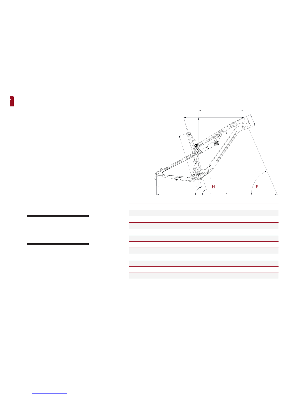
Geometry
C
A
J
GEOMETRY NOTEs
GEOMETRY TAKEN AT TOP OUT WITH 542MM
FORK LENGTH AND 42MM FORK OFFSET.
Component spec NOTE
the recluse is designed around the use
of single or double cha in ring sets only.
Use of a triple ring set will not allow
proper clearance with the frame.
SMALL MEDIUM LARGE XLARGE
A
Wheel Base: 1142 mm/ 45” 1169 mm/ 46” 1196 m m/ 47” 1222 mm/ 48”
B
Top Tube Length: 575 mm/ 22.6” 601 mm/ 23.6” 626 mm/ 24.6” 652 mm/ 25.6”
C
Chain St ay Length: 419 mm/ 16.5” 419 mm/ 16.5” 419 mm/ 16.5” 419 mm/ 16.5”
D
Head Tube Length: 102 mm/ 4” 115 mm/ 4.5” 127 mm/ 5” 127 mm/ 5”
E
Head Tube Angle: 66˚ 66˚ 66˚ 66˚
F
Reach: 417 mm/ 16.4” 438 m m/ 17.3” 460 mm/ 18.1” 486 mm/ 19.2”
G
Stack: 587 mm/ 23.1” 599 mm / 23.6” 611 mm/ 24” 611 mm/ 24”
H
BB Height: 344 mm/ 13.5” 344 mm/ 13.5” 344 mm/ 13.5” 344 m m/ 13.5”
I
Seat Tube Angle (Effect ive): 75˚ 75˚ 75˚ 75˚
J
Seat Tube Angle (Actu al): 72˚ 72˚ 72˚ 72˚
K
Seat Tube Length: 376 mm/ 14.8” 446 mm/ 17.6” 484 mm/ 19” 515 mm/ 20.3”
L
Standover Height: 792 mm / 31.2” 800 mm/ 31.5” 807 m m/ 31.8” 807 mm/ 31.8”
6 // recluse user manual
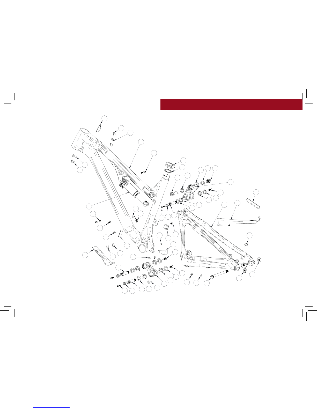
exploded view
and b.o.m.
21
18
35
36
13
29
5
29 6
37
30
33
10
1
25
11
8
3
7
24
12
4
2
28
4
16
14
34
18
22
27
26
23
18
9
38
9
9
20
20
31
16
23
18
17
29
18
17
24
12
3
16
29
18
32
19
15
18

INTENSE CYCLES // 7
ITEM
NO.
ITEM
PART
NUMBER
DESCRIPTION QTY. TORQUE SPEC.
1
Deraill eur Mou nt
Cover
130209 For Single Ring Se tup 1 N/A
2
Box Link 130764 Forged Lo wer Link 1 N/A
3
Bearing Cap
24mm OD
130765
Top Link B earing Spacer
(Lower)
2 N/A
4
Bearing Cap 130778 Box Lin k Bearing Cap 4 N/A
5
Axle Upper 130780
Top Link Pivot Axl e
(U pp er)
1
20 Nm /
175 in-lbs
6
Bolt Shoulder 1 30785 Top Link Pivot B olt 1
20 Nm /
175 in-lbs
7
Spacer 130789 Top Link B earing Spacer (Upper) 2 N/A
8
Hanger 130790 Derailleur Hanger Forged 1 N/A
9
Bolt Ma in Pivot 130791 Box Link Expander Bolt 3
7 Nm /
60 in-lb s
10
Hanger Bolt 130792 Derailleur Hanger Bolt 1
11 Nm /
100 in-lbs
11
Rear Axle 130799 Axle 148 x 12 Boost 1
11 Nm /
100 in-lbs
12
Cone Adjuster 130807 Cone Adjuster Bl k, 8.3 mm Height 3 N/A
13
Top Li nk 130808 Forged Top Link 1 N/A
14
Bumper 140006 Box Link Bumper 1 N/A
15
O-Ring 140013 Seat Clamp o-ring 1 N/A
16
Plug 140038 Box Link Pivot Plug 3 N/A
17
Cable Guide
Grommet
140039
Cable Guide Grommet
(Head Tube)
2 N/A
18
Cable Guide Pl ug 140040 Cable Guide P lug (Thr u) 8 N/A
19
Cable Guide
Grommet
140042
Cable Guide Grommet
(Rear Triangl e)
1 N/A
20
Clip 310001 Cable Guide Clip 2 N/A
21
Seat Collar 346941 Bolt-on 36.1 Blk 1 N/A
ITEM
NO.
ITEM
PART
NUMBER
DESCRIPTION QTY. TORQUE SPEC.
22
Zerk Fitting 401011 M6 x 1.0 2
5 Nm /
40 in-lb s
23
BHCS M5 X 12 410010
Water Bo ttle Bo lt, But ton Head,
M5 X 12
2
6 Nm /
54 in-lb s
24
SHCS M6 x 22 41003 2
Cone Adjuster Bolt, Soc ket Head ,
M6 x 22 Titan ium
3
14 Nm /
125 in-lbs
24ST
SHCS M6 x 22 410009
Cone Adjuster Bolt, Soc ket Head ,
M6 x 22 Stainless Steel
3
14 Nm /
125 in-lbs
25
FHCS M6 x 12 410 037
Front Der ailleur Mount B olt,
Flat Hea d, M6 x 12 Blk
1
7 Nm /
60 in-lb s
26
SHCS M6 x 40 410050
Front Sho ck Bolt, Socket Head,
M6 x 40 Titan ium
1
7 Nm /
60 in-lb s
26ST
SHCS M6 x 40 410053
Front Sho ck Bolt, Socket Head,
M6 x 40 St ainless Steel
1
7 Nm /
60 in-lb s
27
SHCS M6 x 45 4100 51
Rear Shock Bol t, Socke t Head,
M6 x 45 Titanium
1
7 Nm /
60 in-lb s
27ST
SHCS M6 x 45 41 0054
Rear Shock Bol t, Socke t Head,
M6 x 45 Stai nless St eel
1
7 Nm /
60 in-lb s
28
Bearing 7902 430007
15 x 28 x 7 2RS
MAX Angular Contact Bearing
4 N /A
29
Bearing 6802 430008
15 x 24 x 5 2RS
MAX Radial Bearing
4 N /A
30
Guard Flack SS 500254 Flack Gua rd Seat stay 1 N/A
31
Protector Chainstay 500255 Protector Chainstay 1 N/A
32
Guard Flack DT 500256 Flack G uard Dow n Tube 1 N /A
33
Guard Flack CS 500259 Flack Guard Chainstay 1 N/A
34
Decal 500300 Decal California Bear 1 N /A
35
Head Badge 500335 Head Badge Flame Logo 1 N/A
36
Front Triangle Carbon - 4 Sizes 1 N /A
37
Rear Triang le Carbon - 1 Size 1 N /A
38
Rear Shock Shock
7.875in x 2.25in
(200mm x 57mm)
1 N/A

8 // recluse user manual
Assembly
Tools needed
• High Grade, waterproof grease
(Maxima Waterproof Grease
recommended)
• Blue Loctite® #243
• 5mm HEX wrench x2
• 8mm HEX wrench
Recommendation
use Grease on lower linkage bolts
only. use loctite on upper linkage
bolts, dropout bolts and hanger bolt.
PREFAC E //
Service and maintenance on an Intense bicycle requires special tools, abilities and
knowledge of working on bicycles. It is always recommended to use an authorized
Intense dealer for service and maintenance. Always wear eye protection. It is critical
to use the proper tools, loctite, grease and torque specs during assembly. Failure to
follow these instructions may result in serious bodily injury or death.

INTENSE CYCLES // 9
2
3
CONNECTING TOP LINK TO FRONT TRIANGLE //
A Holding top link (#130808) with shock
mount pointed forward, hold upper spacer
(#130789) against insid e of bearing race
(IMAGE #1).
B Match upper link to top tube, making
sure that spacers do not fall out.
C Using upper pivot axle (#130780),
insert through non-drive side of top link
bearing and push through to drive side
bearing, making sure spacers do not fall
out (IMAGE #2). Install shoulder bolt
(#130785) into drive side of top link
pivot, and tighten to 20 NM or 175 in/
lbs (IMAGE #3).
CONNECTING BOX LINK TO FRONT TRIANGLE //
A Hold bearing caps (#130778) with
rounded ends facing outwards against
bearings on box link (#130764), (note
box link orientation (IMAGE #4), with
rubber bumper facing upward and
rearward on box link).
B Match link to front triangle and from
non drive side, insert greased main pivot
bolt (#130791) through the non-drive
side of frame (IMAGE #5).
C Use 8mm HEX to install, then torque
pivot bolt (#130791) to 7 NM or 60 in/lbs.
41 5

10 // r ecluse user manual
6 11
97
108
CONNECTING REAR TRIANGLE TO BOX LINK //
A Follow previous step to connect rear
triangle to box link (IMAGE #6).
B Use 8mm HEX to install, then torque
pivot bolt (#130791) to 7 NM or 60 in/
lbs (IMAGES #7 & 8).
CONNECTING REAR TRIANGLE TO TOP LINK //
A Holding bearing cap (#130765) with
squared edges against the bearing and the
rounded side facing outward (IMAGE #9),
Swing the seat stays up and align with
the lower spacers. From the non drive
side of top link insert greased main pivot
bolt (#130791) through the non-drive
side of frame (IMAGES #9 & 10).
B Use an 8mm HEX to insta ll torq ue main
pivot bolt (#130791) to 7 NM or 60 in/
lbs (IMAGE #11).

INTENSE CYCLES // 1 1
TIGHTENING SEATSTAYS TO TOP LINK //
A Grease and install adjuster cone
(#130807) into head of main pivot bolt
(#130791) and greased M6x22mm bolt
(#410032) through the adjuster cone
into the main pivot bolt (IMAGE #16).
B Using hand pressure, squeeze the top
of seat stay together at the lower top
link location to eliminate side to side
play (IMAGE #17) then use a 5mm HEX
to make snug.
C Torque M6x22mm (#410032) to 14 NM
or 125 in/lbs (IMAGE #18).
INSTALLING REAR SHOCK //
A Holding rear shock match forward
end to forward shock mount, and install
greased M6x40mm bolt (#410050)
through drive side of frame (IMAGE #12).
Do not tighten.
B Match rear end of shock to upper
link and install greased M6x45mm bolt
(#400051) through non-drive side of lin k
(IMAGE #13).
C Torque shock bolts (#410050 &
#400051) to 7 NM or 60 in/lbs (IMAGES
#14 & 15).
1712 14
16 1813 15

12 // recluse user manual
INSTALLING DERAILLEUR HANGER //
A Greas e outer edges of derailleur hanger
(#130790) and loctite derailleur bolt
(#130792) if not pre loctite applied.
B Insert hanger (#130790) into back of
frame opening and match derailleur bolt
(#130792) on the front side threading
bolt into hanger (IMAGE #22 & 23).
C Torque derailleur bolt (#130792) to 11
NM or 100 in/lbs (IMAGE #24).
22
2423
INSTALLING ADJUSTER CONES ON LOWER LINK //
A Grease and install adjuster cone
(#130807) into head of main pivot bolt
(#130791) and greased M6x22mm bolt
(#410032) through the adju ster cone into
the main pivot bolt (IMAGES #19 & 20).
B Torque M6x22mm (#410032) to 14 NM
or 125 in/lbs (IMAGE #21).
19
2120

torque
Achieving proper torque is vital to
ensuring the safe performance and
function of the recluse fr ame. Failure
to do so could result in sub-optimal
performance as well as premature
wear and tear of individual parts.
additional reference
In addition to this chart, all torque
values are laser etched onto
corresponding hardware for your
reference.
INTENSE CYCLES // 1 3
torque chart
20 Nm / 175 in/lbs
7 Nm / 60 in/lbs
7 Nm / 60 in/lbs
M8 HEX 7 Nm / 60 in/lbs
M5 HEX 14 Nm / 125 in/lbs
M8 HEX 7 Nm / 60 in/lbs
M5 HEX 14 Nm / 125 in/lbs
11 Nm / 100 in/lbs
M8 HEX 7 Nm / 60 in/lbs
M5 HEX 14 Nm / 125 in/lbs

seatpost
make sur e to insert seat post at le ast
4” into the main frame. Anything less
than this amount could cause damage
to the frame or even failure.
14 // recluse user manual
set up
4”

INTENSE CYCLES // 1 5
shock setup
rock shox monarch rC3 / R 200 x 57mm
set up and tune
proper set up and tuning can
vary from shock to shock. Please
consult the rockshox manual
included with your bike for complete
information about set up, tuning
and genera l maintenance or visit
www.sram.com/rockshox/products
Trav el 140 mm
Shock Stoke
57 mm
Shock Sag
20% when sitting on the bike
Fork Sag
25-30% when sitting on the bike
SHOCK: Recluse 275 Expert
Rock Sh ox Monar ch RC3 200x57 mm DB2 MM S 320
SHOCK: Recluse 275 Foundation
Rock Sh ox Monar ch R 200x57 mm DB2 MM S 320
RIDER W EIGHT (LB S/KGS) SPRING (PSI) REBOUND (clicks out)
100 LB S / 45 KGS
80
2 to 3
110 LB S / 50 KGS
88
120 LB S / 54 KGS
97
130 LB S / 59 KGS
105
140 LB S / 63.5 KGS
114
150 LB S / 68 KGS
122
3 to 4
160 LB S / 73 KGS
131
170 LB S / 77 KGS
139
180 LB S / 82 KGS
148
190 LB S / 86 KGS
156
200 LBS / 9 1 KGS
164
210 LB S / 95 KGS
173
220 LB S / 100 KGS
181
230 LB S / 104 KGS
190
5 to 6
240 LB S / 109 KGS
198
250 LB S / 113 KGS
207
260 LB S / 118 KGS
215
270 LB S / 122 KGS
224
280 LB S / 127 KGS
232
290 LB S / 131.5 KGS
241
300 LB S / 136 KGS
249

16 // r ecluse user manual
shock setup
FOX FLOAT X2 200 x 57mm
set up and tune
proper set up and tuning ca n vary
from shock to shock. Ple ase
consult the Fox manual included
with your bike for complete
information about set up, tuning
and genera l maintenance or visit
www.foxracingshox.com
Trav el 14 0 mm
Shock Stoke
57 mm
Shock Sag
20% when sitting on the bike
Fork Sag
25-30% when sitting on the bike
SHOCK: Recluse 275 Factory
FOX Shox, FLOAT X2, F-S, K, 2POS Lever, 200x57 m m
SHOCK: Recluse 275 Pro
FOX Shox, FLOAT X2, P-SE, A, 2P OS Lever, 200 x57 mm
RIDER WEIGHT(LBS/KGS) SPRING (PSI)
100 LB S / 45 KGS
100
110 LB S / 50 KGS
111
120 LB S / 54 KGS
121
130 LB S / 59 KGS
132
140 LB S / 63.5 KGS
142
150 LB S / 68 KGS
152
160 LB S / 73 KGS
163
170 LB S / 77 KGS
173
180 LB S / 82 KGS
184
190 LB S / 86 KGS
194
200 LBS / 9 1 KGS
204
210 LB S / 95 KGS
215
220 LB S / 100 KGS
225
230 LB S / 104 KGS
235
240 LB S / 109 KGS
246
250 LB S / 113 KGS
256
260 LB S / 118 KGS
267
270 LB S / 122 KGS
277
280 LB S / 127 KGS
287
290 LB S / 131.5 KGS
298
300 LB S / 136 KGS
308

INTENSE CYCLES // 1 7

18 // r ecluse user manual
maintenance
GENERAL SERVICE AND CARE //
You have pu rchased a high per for ma nce bic ycle which requires a cer tain level of service
and maintenance to sustain the level of performance your frame was designed around.
Proper care will also ensure the bike is safe to ride at all levels. It is important to read
and und ersta nd the carb on care info rmation as wel l as follow the maintenanc e schedul e
and ins pect your bicycle before each ride. These will not only help to limit or avo id costly
repairs but will also help to avoid injury due to service neglect and component failure.
carbon care
Intense Cycles employs advanced comp osite techniques and materials in
our frames which do require a certain level of care and maintenance to
ensure a safe experience at the high level of performance each frame is
designed around. Not fol lowing these guidelines will decrease the level
of performance and possibly cause injury or death.
• Use a soft cloth with warm soapy water to clean the carbon surfaces. Do
not use abrasive cloths or cleaners.
• Be sure all frame surfaces in contact with cables are protected. Cable
housing rubbing on carbon can wear over time.
• Be sure brake levers, handle bar ends and the fork crown do not contact
the frame at full rotation.
• Never clamp any part of a carbon frame in a bike stand or car rack.
• Always inspect your frame if you experience any chain suck. Intense
frames come equipped with steel chain suck plates but damage can still
be done in the event of chain suck.
• Always inspect your frame in full after a crash to be sure there is no
damage. Look for cracks, dents or loose fibers. If you discover damage
in any degree it’s best to have your frame inspected by a qualified
Intense Cycles dealer. Any direct impact to the frame can cause serious
structural damage.
• Use high grade waterproof grease on seat post, BB and head set bearing
contact areas with the carbon.
• Never ream or face a carbon frame.
• Be sure to follow all recommended torque settings.

INTENSE CYCLES // 1 9
maintenance Schedule*
Action Every Ride
500 Mil es or
1 Month
2000 Mil es or 6
Months
4000 Mi les or
1 Year
Tires
Check air pre ssure, i nspec t tread and sid ewalls fo r tears and pu ncture s X
Chain
Brush off and lubrica te X
Brakes
Squeeze brakes and confirm function X
General
Clean c omplete bike o f mud and debris X
Headset
Check adjustment X
Box Lin k
Add gre ase thru zerk fittings X
Frame Pivots
Check torques X
Spokes
Inspect for damage, check tension X
Shock a nd Fork
Check air pre ssure, i nspec t for lea ks X
Deraileur Cables
Inspect and lube X
Seat post
Clean and regrease interface with frame X
Frame Pivots
Remove pivot bo lts, ch eck bea rings for pittin g and wear X
Headset
Disass emble stem, headset and fork. Chec k bearin gs for pitting a nd wear X
Hubs
Pull wh eels off, c heck hub bearings for pitting and wea r X
Bottom Bracket
Remove crank a rms an d check BB bea rings for pittin g and wear X
Brakes
Replace brake p ads X
Chain
Inspe ct for da mage and chec k for str etching X
General
Complete Tune-Up X
Shock a nd Fork
Overhaul See MFG Recommendations
* THE ABOVE MAINTENANCE SCHEDULE IS ONLY A GUIDELINE. refer to COMPONENT MANUFACTURER FOR SPECIFIC INSTRUCTION ON MAINTAINING THEIR PARTS.

phone: (951)-296-9596
Customer Service: cs@intensecycles.com
General Info: info@intensecycles.com
Media, Marketing, Sponsorship: marketing@intensecycles.com
Intense Cycles USA 42380 rio nedo Temecula, Ca. 92590
www.I NTENS eCYCLES. com
330020
 Loading...