


user manual PRIMER 29

introduction / registration 2
frame features / component spec 4
Geometry 5
exploded view and b.o.m. 6
Assembly 8
torque chart 13
setup 14
maintenance 18
AT INTENSE, WE H AVE ONE GOAL - TO P ROVIDE THE RIDE OF YOUR LIF E //
Our team of design ers, engineers a nd product exper ts are focused on one thing every
day: your experience o n the bike. We build bikes that are as thrilling to loo k at as they
are to ride, and we build t hem for the select few of you who underst and the difference
and refuse to settle for a nything else.
From the early days of Inte nse, when founder Jeff Steber worked a lone in his garage to
today, where a crew of tale nted people work in a Temecula, CA factor y, Intense has been
a brand built on pass ion by forward thinker s who, even today, love nothi ng more than
to throw a leg over a sweet b ike and head out for a rip. We’re so glad you’ve joined us.
Welcome to Intense, e njoy your experience.
THE PRIMER 29 //
Designed for the big wh eel, trail enthusia st, the Primer 29 spor ts 4.5” or 5” of rear
wheel travel on an ext ra wide, Boost 148 rear end. The carbon front an d rear triangles
provide an exceptio nally stiff yet comforta ble ride that is light an d nimble. The bike
is race ready and featu res internal cab le routing, 160mm post m ounts and prote ctive
flak guards as stand ard amenities.
registration
WWW.INTENSECYCLES.COM/WARRANTY-CARD/
contact customer service
cs@intensecycles.com
951-296-9596
Welcome to
the family
2 // PRIMER 29 user manual INTENSE CYCLES // 3

4 // PRIMER 29 user manual INTENSE CYCLES // 5
frame
features /
spec
Geometry
C
A
B
F
E
D
G
H
L
K
I
J
GEOMETRY NOTEs
GEOMETRY TAKE N AT TOP OUT WITH 538MM
FORK LENGT H AND 51MM FORK OF FSET.
Component spec NOTE
the PRIMER 29 is d esigned around the
use of single or do uble chain ri ng
sets only. Use of a triple rin g set will
not allow pro per clearance w ith the
frame.
SMALL MEDIUM LARGE XLarge
A
Wheel Base: 1130 mm/ 44.5” 115 6 mm/ 45.5” 11 8 1 m m / 4 6. 5” 12 0 7 m m / 4 7.5 ”
B
Top Tube Lengt h: 572 mm/ 22.5 ” 597 mm / 23.5” 622 mm/ 24. 5” 648 mm/ 25.5”
C
Chain Stay Length: 438 mm/ 17.25” 438 mm/ 17.25” 438 mm/ 17.25” 438 mm/ 17.25”
D
Head Tu be Length : 94 mm/ 3.7” 102 mm/ 4” 114 mm/ 4.5 ” 119 mm/ 4.7”
E
Hea d Tube Angle: 67. 5 ˚ 6 7.5 ˚ 6 7.5 ˚ 67. 5 ˚
F
Reach: 40 8 m m/ 1 6.1 ” 431 mm / 17” 453 mm/ 17.8” 4 77 mm/ 18.8”
G
Stac k: 609 mm/ 2 4” 616 mm / 24.25” 628 mm/ 24.7” 632 mm/ 24.9”
H
BB Hei ght: 337 m m/ 1 3.25” 337 mm/ 13.25 ” 33 7 mm/ 13.2 5” 33 7 mm / 13 .25”
I
Seat Tube Angle (Effective): 75˚ 75˚ 75˚ 75˚
J
Seat Tube Angle (Actual): 72.3˚ 72.3˚ 72.3 ˚ 72.3˚
K
Seat Tube Length: 432 mm/ 17” 457 mm/ 18” 4 83 mm/ 1 9” 508 mm/ 20”
L
Standover Height: 800 m m/ 31.5 ” 80 3 mm/ 3 1.6” 809 mm/ 31.8” 811 mm/ 31.9”
Frame Features //
• Adjustable Travel: 4.5" to 5" (115mm-130mm)
• 29” Wheel size
• 5.8 lbs / 2,620 grams = Stand ard frame w/ alloy l ink, no shock, size m
• 5.2 lbs / 2,380 grams = SL S uper Light fram e w/carbon link, no sho ck, size m
• Tapered Head Tube
• Monocoque front triangle
• Integrated BOOST 148 x 1 2 dropouts
• Internal Brake and D erailleur Ca ble Routing System
• Internal Seat Tube Cabl e Routing for drop per posts
• Angular Contact/Colle t Bearing System w ith replacea ble Grease Zerks
• Flack guard Downtu be and Chainstay protec tion
• H20 Bottle Fitment
Component Spe c //
• Fork – 1.5” tapered steer, 13 0mm Travel, 538mm low er leg length, 51mm of fset
• Shock – 200mm x 50.8mm (7.875” x 2”), 22mm x 6mm and 30 mm x 6mm reducers
• Front derailleur – Dir ect Mount
• Seat post – 31.6mm
• Headset – zero stack 44 upp er / external cup 4 9 lower
• Bottom bracket - Pres s Fit BB92
• Rear Axle – BOOST 14 8 x 12 T/A
• Brake Mount – internation al standard for 160mm r otor
• Crank set - BOOST 148 C ompatible - single or doubl e ring only
• Rear Wheel - BOOST 14 8 Compatible
6 // PRIMER 29 user manual INTENSE CYCLES // 7
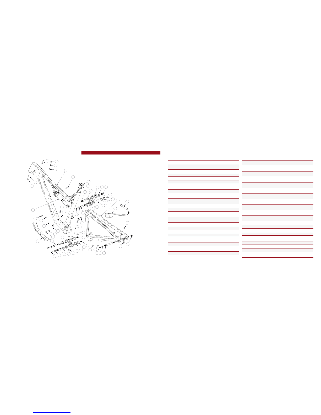
exploded view
and b.o.m.
22
19
36
37
4
30
8
30 9
38
31
34
13
1
26
2
11
6
10
25
14
7
5
29
7
17
15
35
19
23
28
27
24
19
12
39
12
12
21
21
32
17
24
19
18
30
19
18
25
14
6
17
30
19
20
33
19
16
19
3
1425
ITEM
NO.
ITEM
PAR T
NUMBER
DESCRIPTION QTY.
TORQUE
SPEC.
1
Derailleur Mount Cover 130209 For Single Ring Setup 1 N/A
2
Re ar Ax le 130757 Axle 148 x 12 Boost Locking Blk 1
11 Nm /
100 in-lbs
3
Bear ing S pace r 130759 Top Link Bearing Spacer (Lower) 1 N/A
4
Top L ink 1 30762 Forged T op Link 1 N/A
4
Top L ink 1 30760 Carb on To p L ink 1 N/A
5
Box Link 130764 Forged Lower Link 1 N/A
6
Bear ing Cap
24mm OD
130765 Top L ink Bearing Cap (Lower) 2 N/A
7
Bear ing Cap 130778 Box L ink Bearing Cap 4 N/A
8
Axle Upper 130780 Top Li nk Pivot Axle (Upper) 1
20 Nm /
175 in-lbs
9
Bolt Should er 130785 Top Link Pivot Bolt 1
20 Nm /
175 in-lbs
10
Spacer 130789 Top Link Bearing Spacer (Upper ) 2 N/A
11
Hanger 1307 90 Derai lleur Hanger Forged 1 N/A
12
Bolt Main Pi vot 1307 91 Bo x Link E xpand er Bolt 3
7 Nm /
60 in-lbs
13
Hanger Bolt 130798 Derailleur Hanger Bolt 1
11 Nm /
100 in-lbs
14
Con e Adju ster 130807 Cone Adjuster Blk, 8.3 mm Height 4 N/A
15
Bumper 140006 Box L ink Bumper 1 N/A
16
O-Ring 140013 Se at Clamp o-ring 1 N/A
17
Plug 140038 Box Link Pivot P lug 3 N/A
18
Cable Guide
Gromm et
140039
Cable Guide Grommet
(Head Tub e)
2 N/A
19
Cable Guide Plug 140040 Cable Guid e Plug (Thru) 8 N/A
20
Cable Guide
Gromm et
140042
Cable Guide Grommet
(Rear Triangle)
1 N/A
21
Clip 310001 Cable Guide Clip 2 N/A
22
Seat Co llar 346941 Bo lt - on 36. 1 B lk 1 N /A
ITEM
NO.
ITEM
PAR T
NUMBER
DESCRIPTION QTY.
TORQUE
SPEC.
23
Zerk Fi tting 401011 M 6 x 1.0 2
5 Nm /
40 in-lbs
24
BHCS M 5 X 12 410010
Water Bot tle Bolt,
Butt on H ead, M5 X 12
2
6 Nm /
54 in-lbs
25
SHCS M 6 x 22 410009
Con e Adju ster Bolt,
Socket Head, M 6 x 2 2
4
14 Nm /
125 in-lbs
25
SHCS M 6 x 22 41 0032
Con e Adju ster Bolt,
Socket Head, M 6 x 22 T itanium
4
14 Nm /
125 in-lbs
26
FHCS M6 x 12 41003 7
Front D erailleur Mount Bolt,
Flat Head , M6 x 1 2 Blk
1
7 Nm /
60 in-lbs
27
SHCS M 6 x 40 410053
Front Shock Bolt,
Socket Head, M6 x 40
1
7 Nm /
60 in-lbs
27
SHCS M 6 x 40 410050
Front Shock Bolt, Socket Head,
M6 x 40 Titanium S275C SL
1
7 Nm /
60 in-lbs
28
SHCS M 6 x 45 410054
Rear Shock Bolt,
Socket Head, M6 x 45
1
7 Nm /
60 in-lbs
28
SHCS M 6 x 45 410 051
Rear Shock Bolt, Socket H ead,
M6 x 45 Titanium S275C SL
1
7 Nm /
60 in-lbs
29
Bear ing 7 902 430007
15 x 28 x 7 2RS
MAX Angular Contact Bearing
4 N/A
30
Bear ing 6 802 430008
15 x 24 x 5 2RS
MAX Radial Bearing
4 N/A
31
Guard Flack SS 5002 54 Flac k Guard S275C Seatstay 1 N/A
32
Pro tec tor Chai nsta y 500255 Chain Stay Protector 1 N /A
33
Guard Flack D T 500 262 Down Tube Flack Guard 1 N/A
34
Guard Flack CS 50 0263 Chainstay Flack Guard 1 N/A
35
Decal California
Bear
500300 Decal California Bear 1 N/A
36
Head Badge 50 0335 Head Badge Flame Lo go 1 N/A
37
Front Tr iangle Carb on, 4 Siz es 1 N /A
38
Rear Triangle Carb on, 1 Siz e 1 N/A
39
Shock
Rear Shock 7.875” x 2”
(200mm x 50.8mm)
1 N/A
(ST)
(ST)
(ST)
(ST)

8 // PRIMER 29 user manual INTENSE CYCLES // 9
Assembly
Tools needed
• High Grade, waterproof greas e
(Maxima Waterproof Gre ase
recommended)
• Blue Loctite® #243
• 5mm HEX wrench x2
• 8mm HEX wrench
Recommendation
use Grease on low er linkage bolts
only. use loctite on upper link age
bolts, dropout bolts an d hanger bolt.
PR EFA CE //
Service and maint enance on an Intense bicycle requires spec ial tool s, abili ties and
knowledge of working on b icycles. It is always recommend ed to use an aut horized
Intense dealer for service and maintenance. Always wear eye prot ection. It i s critical
to use th e prop er tool s, loctite, grease and torque specs during assembly. Failure to
fol lo w th ese in struc tion s may r esult in ser ious b od ily injury o r d eat h.
2
3
CONNECTING T OP LINK TO FRON T TRIANGLE //
A Hold ing top link (#130760) wit h
shock mount pointed forward, hold upper
spacers (#130789) against in side of
bearing race (IMAGE #1).
B Match upp er link t o top tube, making
sure that spac ers do not fal l out.
C Using upper pivot axle (#130780),
insert through n on-drive side of top
link bearing and pu sh through to drive
side bearing, mak ing sure spacers do not
fall out (IMAGE #2). Install shoulder bolt
(#130785) into drive side of top link
pivot, and tighten to 20 NM o r 175 in/
lbs (IMAGE #3).
CONNECTING B OX LINK TO FRONT TRIANGLE //
A Hold bearing cap s (#130778) with
rounded ends facin g outwards against
bearings on box link (IMAGE #4), (note
box link orientation in i mage #4, with
rubber bumper facing upward and
rearward on box link).
B Match link to fron t triangle and from
non drive side, ins ert greased main pivot
bolt (#130791) through the non-drive
side of frame (IMAGE #5).
C Use 8mm HEX to install, th en torque
pivot bolt (#130791) to 7 NM or 60 in/lbs.
41 5

10 // PRIMER 29 user manual INTENSE CYCLES // 1 1
TIGHTENING S EATSTAYS TO TOP LINK //
A Grease and insta ll adjuster cone
(#130807) into head of main pivot bo lt
(#130791) and greased M6x22mm bolt
(#410032) through the adjuster cone
into the main pivot bo lt (IMAGE #14).
B Using hand press ure, squeeze the t op
of seat stay togethe r at the lower top
link location to elim inate side to side
play (IMAGE #15) then use a 5mm HEX
to make snug.
C Torque M6x22mm (#410032) to 14 NM
or 125 in/lbs (IMAGE #16).
INSTALLING RE AR SHOCK //
A Holding rear shoc k match forward end to for ward shock mount, a nd install grease d
M6x40mm bolt (#410050) through drive side of frame (IMAGE #10). Do not tighten.
B Match rear end of sho ck to desired travel s etting (see below) on upper link and
install greased M6x45mm bolt (#410051) through non-drive side of link (IMAGE #11).
C Torque shock bolts (#410050 & #410051) to 7 NM or 60 in/lbs (IMAGES #12 & 13).
adjustable travel NOTE
the top link of the P RIMER 29 features dual mo unting positions. The U pper shock
mounting hole o n top link is for LONG travel , the lower hole is for S HORT travel.
for more inform ation see the set up guide on page 1 4.
7
6
8
9
1510 12
14 1611 13
CONNECTING REAR TRIANGLE
TO BOX LINK //
A Follow previous step to co nnect rear
triangle to box link (IMAGES #6 & 7).
B Use 8mm HEX to install, th en torque
pivot bolt (#130791) to 7 NM or 60 in/lbs.
CONNECTING REAR TRIANGLE
TO TOP LINK //
A Holding spacers (#130765) with squared
edges against the be aring and the rounded
side facing outward (IMAGE #8), Swing
the seat stays up and a lign with the lower
spacers. From the non d rive side of top
link, install greas ed pivot bolt (#130791)
(IMAGE #9). Use an 8mm HEX to install.
B Use an 8mm HEX to instal l torque
main pivot bolt (#130791) to 7 NM or
60 in/lbs.
INSTALLING ADJUSTER CONES ON LOWER LINK //
A Grease and insta ll adjuster cone
(#130807) into head of main pivot b olt
(#130791) and greased M6x22mm bolt
(#410032) through the adjuster cone into
the main pivot bolt (IMAGES #17 & 18).
B Torque M6x22mm (#410032) to 14 NM
or 125 in/lbs (IMAGE #19).
17
1918

torque
Achieving pro per torque is vital to
ensuring the sa fe performa nce and
function of the P RIMER 29 fra me.
Failure to do so coul d result in suboptimal performance of your frame
as well as prem ature wear and tear
of individual pa rts.
additional reference
In addition to this c hart, all torque
values are laser e tched onto
corresponding hardware for your
reference.
12 // PRIMER 29 user manual INTENSE CYCLES // 1 3
torque chart
20 Nm / 175 in/lbs
7 Nm / 60 in/lbs
7 Nm / 60 in/lbs
M8 HEX 7 Nm / 60 in/lbs
M5 HEX 14 Nm / 125 in/lbs
M8 HEX 7 Nm / 60 in/lbs
M5 HEX 14 Nm / 125 in/lbs
M8 HEX 7 Nm / 60 in/lbs
M5 HEX 14 Nm / 125 in/lbs
11 Nm / 100 in/lbs
INSTALLING DERAILLEUR HANGER //
A Grease outer edge s of derailleur
hanger (#130790) and loctite derailleur
bolt (#130798) if not pre loctite app lied
(IMAG E #20).
B Insert hanger (#130790) into back of
frame opening and m atch derailleur b olt
(#130798) on the front side threading
bolt into hanger (IMAGE #21).
C Torque derailleur bolt (#130798) to
11NM or 100 in/lbs (IMAGE #22).
REAR AX LE //
A The Primer uses a rea r axle with an
expanding collet s ystem similar to our
main pivot bolts. Th is ensures a secu re
fit between the axle an d frame (IMAGE
#23). To install rear axle, in sert threaded
end of axle through n on-drive side
dropout until it rea ches female threaded
end of hanger. You can then inser t a 5mm
allen through ope ning on the hanger bolt,
which will allow you to tight en axle in
a counterclockwise (rearward) direction
to 100 in/lb (IMAGE #24). You may then
grease and instal l the cone adjuster into
the opening on the n on-drive side of the
axle, then insert M6x25mm b olt into cone
adjuster and tighten to 125 in/lb s.
20
2221
23 24

seat post
make sure to inse rt seat post at least
4” into the main fr ame. Anything less
than this amo unt could cause da mage
to the frame or e ven failure.
14 // PRIMER 29 user manual INTENSE CYCLES // 1 5
shock setup
rock shox monarch rt3 / R 200 x 51mm
set up and tune
proper set up a nd tuning can
vary from shock to sh ock. Pleas e
consult the rockshox m anual
included with yo ur bike for complete
information about set up, tuning
and general m aintenanc e or visit
www.sram.com/rockshox/products
set up
adjustable travel
upper mount: 130mm
lower mount: 115m m
upper mount
lower mount
4”
Travel 115 mm 130 mm
Shock Stoke
51 mm
Shock Sag
20% wh en sitting on th e bike
Fork Sag
25-30% wh en sitting on t he bike
SHOCK: Primer 29 Expert
Rock Shox Monarch RT3 200x51 mm DB2 MM S 320
SHOCK: Pri mer 29
Foundation
Rock Sho x Monarch R 200x51 mm DB2 MM S 320
RIDER WEIG HT (LBS/KG S) SPRING (PSI) REBOUND (clicks out) SPRING (PSI) REBOUND (clicks out)
100 LBS / 45 KGS
103
2 to 3
98
2 to 3
110 LBS / 50 KGS
116 114
120 LBS / 54 KGS
130 130
130 LBS / 59 KGS
144 146
140 LBS / 63. 5 KGS
157 162
150 LBS / 68 KGS
171
3 to 4
177
3 to 4
160 LBS / 73 KGS
185 193
170 LBS / 77 KG S
198 209
180 LBS / 82 KGS
212 225
190 LBS / 86 KGS
226 241
200 LBS / 91 KGS
239 256
210 LBS / 95 KGS
253 272
220 LBS / 100 KGS
267 288
230 LBS / 104 KG S
281
5 to 6
304
5 to 6
240 LBS / 109 KG S
294 319
250 LBS / 113 KG S
308 335
260 LBS / 118 KG S
322 351
270 LBS / 122 KG S
335 367
280 LBS / 127 KGS
349 383
290 LBS / 131 .5 KGS
363 398
300 LBS / 136 KGS
376 414

16 // PRIMER 29 user manual INTENSE CYCLES // 1 7
shock setup
FOX FLOAT DPS 200 x 51mm
Travel 115 mm 130 mm
Shock Stoke
51 mm
Shock Sag
20% wh en sitting on th e bike
Fork Sag
25-30% wh en sitting on t he bike
SHOCK: Primer 29 Factory
FOX Sh ox , FLOAT D PS, F-S, K, 3PO S-ADJ EV OL LV, 2 00×51 mm CM, RM, CLIMB
SHOCK: Pri mer 29 Pro
FOX Sh ox , FLOAT D PS, P-SE, A, 3POS-ADJ EVOL L V, 200×51 mm CM, RM, CLI MB
RIDER WEIG HT (LBS/KG S) SPRING (PSI) REBOUND (clicks out) SPRING (PSI) REBOUND (clicks out)
100 LBS / 45 KGS
76
3 to 4
86
3 to 4
110 LBS / 50 KGS
88 98
120 LBS / 54 KGS
100 110
130 LBS / 59 KGS
112 122
140 LBS / 63. 5 KGS
124 134
150 LBS / 68 KGS
136
5 to 6
146
5 to 6
160 LBS / 73 KGS
148 158
170 LBS / 77 KG S
161 171
180 LBS / 82 KGS
173 183
190 LBS / 86 KGS
185 195
200 LBS / 91 KGS
197 207
210 LBS / 95 KGS
209 219
220 LBS / 100 KGS
221 231
230 LBS / 104 KG S
233
7 to 8
243
7 to 8
240 LBS / 109 KG S
245 255
250 LBS / 113 KG S
257 267
260 LBS / 118 KG S
269 279
270 LBS / 122 KG S
282 2 92
280 LBS / 127 KGS
294 304
290 LBS / 131 .5 KGS
306 316
300 LBS / 136 KGS
318 328
set up and tune
proper set up and tuning can vary
from shock to shock. Please
consult the Fox manu al included
with your bike for c omplete
information about set up, tuning
and general m aintenanc e or visit
www.foxrac ingshox.com

18 // PRIMER 29 user manual INTENSE CYCLES // 1 9
maintenance
maintenance Schedule*
Action Every Ride
500 Miles or
1 Month
2000 Miles or 6
Months
4000 Miles o r
1 Year
Tires
Check air pres sure, inspect tread a nd sidewalls for tears an d punctures X
Chain
Brush off and lub ricate X
Brakes
Squeeze brakes and confirm function X
General
Clean comple te bike of mud and debris X
Headset
Check adjustment X
Box Link
Add grease thr u zerk fittings X
Frame Pivots
Check torques X
Spokes
Inspect for damage, check tension X
Shock and Fo rk
Check air pres sure, inspect for leak s X
Deraileur Cables
Inspect and lube X
Seatpo st
Clean and regrease interface with frame X
Frame Pivots
Remove pivot bo lts, check bearings for pi tting and wear X
Headset
Disassemb le stem, headset and for k. Check bearings for pit ting and wear X
Hubs
Pull wheels off, che ck hub bearings for pitti ng and wear X
Bottom Bracket
Remove crank ar ms and check BB bearin gs for pitting and wear X
Brakes
Replace brake pa ds X
Chain
Inspect for da mage and check for stretc hing X
General
Complete Tune-Up X
Shock and Fo rk
Overhaul See MFG Recommendations
GENERAL SE RVICE AND CARE //
You have purchased a high pe rformance bicycle which requi res a certain level of service
and maintenanc e to sustain the level of performanc e your frame was designed around.
Proper care will al so ensure the bike is safe to ride at all levels. I t is important to read
and understand t he carbon care information as well a s follow the maintenance sched ule
and inspect you r bicycle before each ride. These wil l not only help to limit or avoid costl y
repairs but will als o help to avoid injury due to service negle ct and component failure.
carbon care
Intense Cycles e mploys advanced c omposite tech niques and material s in
our frames wh ich do require a certain lev el of care and main tenance to
ensure a safe e xperience at the high le vel of performa nce each fra me is
designed aroun d. Not following the se guidelines will dec rease the leve l
of performa nce and possibly cause in jury or death.
• Use a so ft cloth with warm soapy water to clean the ca rbon surfaces. Do
not use abrasive c loths or cleaners.
• Be sure a ll frame surfaces in contact with cable s are protected. Cable
housing rubbin g on carbon can wear over time.
• Be sure b rake levers, handle bar ends and th e fork crown do not co ntact
the frame at full rotation.
• Never cl amp any part of a carbon frame in a bike stan d or car rack.
• Always in spect your frame if you experience a ny chain suck. Intense
frames come equi pped with steel chain suck plates but d amage can still
be done in the event of c hain suck.
• Always in spect your frame in full after a crash to be su re there is no
damage. Look for crac ks, dents or loose fibers. If you disco ver damage
in any degree it’s best to have yo ur frame inspected by a qualified
Intense Cycles dea ler. Any direct impa ct to the frame can cause serious
structural damage.
• Use high g rade waterproof grease on seat po st, BB and head set bearing
contact areas with the carbon.
• Never re am or face a carbon frame.
• Be sure t o follow all recommended torque s ettings.
* THE ABOVE MAINTENANCE SCHEDULE IS ONLY A GUIDELINE. refer to COMPONENT MANUFACTURER FOR SPECIFIC INSTRUCTION ON MAINTAINING THEIR PARTS.

phone: (951)-296-9596
Customer Service: cs@intensecycles.com
General Info: info@intensecycles.com
Media, Marketing, Sponsorship: marketing@intensecycles.com
Intense Cycles USA 42380 rio nedo Temecula, Ca. 92590
www.I NTENSeCYCLES.com
330019
 Loading...