

user manual m16 Carbon

introduction 2
frame features / component spec 4
Geometry 5
exploded view and b.o.m. 6
Assembly 8
torque chart 14
setup 15
maintenance 18
AT INTENSE, WE H AVE ONE GOAL - TO PRO VIDE THE RIDE OF YOUR LIFE.
Our team of design ers, engineers a nd product expe rts are focused on on e thing every
day: your experience o n the bike. We build bikes that are as thrilling to loo k at as they
are to ride, and we build t hem for the select few of you who underst and the difference
and refuse to settle for a nything else.
From the early days of Inte nse, when founder Jeff Steber worked a lone in his garage to
today, where a crew of tale nted people work in a Temecula, CA factor y, Intense has been
a brand built on pass ion by forward thinker s who, even today, love noth ing more than
to throw a leg over a sweet b ike and head out for a rip. We’re so glad you’ve joined us.
Welcome to Intense, e njoy your experience.
THE M16 CARB ON
This is a serious bike… Full DH in Full carb on. Our standard v ersion comes wit h robust
stainless hardwa re and a bombpro of carbon layup cr eating a strong, race r eady sled.
Kick it up a notch to our SL ve rsion to get titanium b its, a carbon top lin k and an
extra lite carbon lay up. Both use the sa me DH race geometr y, an asymmetrical s wing
arm for easy shock re moval and Intens e suspension tha t will get you to the top of
the podium… Fast.
registration
WWW.INTENSECYCLES.COM/WARRANTY-CARD/
contact customer service
cs@intensecycles.com
951-296-9596
Welcome to
the family
2 // m16C user Manual INTENSE CYCLES // 3
4 // m16C user Manual INTENSE CYCLES // 5
frame
features /
spec
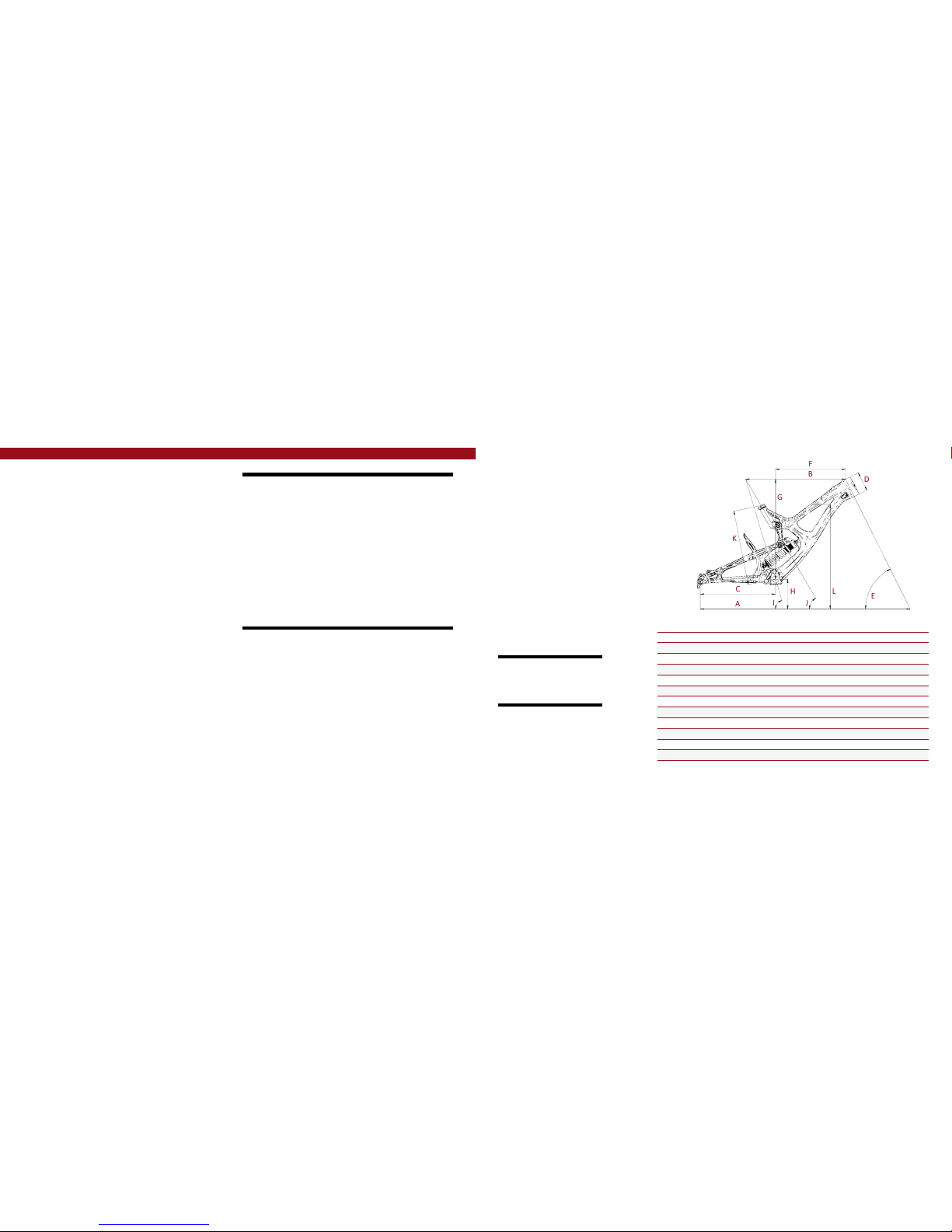
Geometry
A
B
C
F
E
D
G
H
L
K
I
J
GEOMETRY NOTEs
GEOMETRY TAKEN AT TOP OU T WITH 594MM
FORK LENGTH A ND 42MM FORK OFFS ET.
Component spec NOTE
the m16c is design ed around the use of
a single chain rin g set only. Use of a
double or tripl e ring set will not al low
proper cle arance with the f rame.
SMALL MEDIUM LARGE XLarge
A
Wheel Base 1194 mm/ 47” 1219 mm/ 48” 1245 mm/ 49” 1265 mm/ 49.8”
B
Top Tube Length 565 mm/ 22.25” 591 mm/ 23.25” 616 mm/ 24.25” 634 mm/ 25”
C
Chain Stay Lengt h 445 mm/ 17.5” 445 mm/ 17.5” 445 mm/ 17.5” 445 mm/ 17.5”
D
Head Tube Length 109 mm/ 4.3” 115 mm/ 4.5” 122 mm/ 4.8” 132 mm/ 5.2”
E
Head Tube Angle 63.5˚ 63.5˚ 63.5˚ 63.5˚
F
Reach 391 mm/ 15.4” 413 mm/ 16.3” 436 mm/ 17.15” 452 mm/ 17.8”
G
Stack 587 mm/ 23.1” 592 mm / 23.3” 598 mm/ 23.55” 607 mm/ 23.9”
H
BB Height 365 mm/ 14.375” 365 mm/ 14.375” 365 mm/ 14.375” 365 mm/ 14.375”
I
Seat Tube Angle (Effectiv e) 73.3˚ 73.3˚ 73.3˚ 73.3˚
J
Seat Tube Angle (Actual) 59.5˚ 59.5˚ 59.5˚ 59. 5˚
K
Seat Tube Length 416 mm/ 16.4” 440 mm/ 17.3” 455 mm/ 17.9” 457 mm/ 18”
L
Standover Height 797 mm/ 31.4” 803 mm/ 31.6” 809 mm/ 31.9” 816 mm / 32.1”
Frame features //
• Adjustable travel – 8.5” or 9.5” (215mm or 24 1mm)
• 27.5" wheel size
• Progressive Shock Curve
• Tapered Head Tube
• ISCG 05 Mounts
• Modern DH Race Geometry
• Integrated 157mm X 12mm dro pouts
• Internal Cable Rout ing System
• Angular Contact Bearin g / Collet 15MM Ax le System with
replaceable Grease Zerks
• FLack GuaRD Chain stay & Down tu be Protection
• Integrated fork bumper/ca ble guide system
• Non-symmetric rear triangle
Component spec
• Fork – accepts 1.125" straigh t steer or 1.125"/1.5" tapered steer, 200 mm Travel,
594mm lower l eg length, 42mm off set
• Shock – 9.5” x 3”(241mm x 76mm), 22mm x 8mm and 34 mm x 8mm reducers
• Chain Guide Mount - ISCG-05
• Seat post – 31.6mm
• Headset – zero stack 49mm up per / 56mm lower cup s
• BOTTOM BRACKET - THR EADED 83MM
• Rear Axle – 157mm x 12 mm TA
• Brake Mount – internation al standard for 200mm ro tor

6 // m16C user Manual INTENSE CYCLES // 7
ITEM
NO.
ITEM
PART
NUMBER
DESCRIPTION Q TY. TORQUE SPEC.
1
Bearing Spacer 130754 Lower Link Bearing Spacer 2 N/A
2
Bolt Shoulder 130766 Top Lin k Pivot Bolt, Lower Pivot 2 20 Nm / 175 i n-lbs
3
Top Li nk 130768 Forged Top Link 1 N /A
3
Top Li nk 130767 Carbon Top Link 1 N/A
4
Box Link 130769 Forged Lower Link 1 N/A
5
Bearing Cap 130778 Box Link Bearing C ap 4 N/A
6
Axle Upper 130780 Top Link Pivot Axle 1 20 N m / 175 in-lbs
7
Washer 1 30784 Top Lin k Pivot, Lower Washer 2 N/A
8
Bolt Shoulder 130785 Top Link Pivot Bolt, Upper Pivot 1 20 Nm / 175 in-lbs
9
Spacer 130789 Top Link P ivot, Upper Spacer 2 N/A
10
Hanger 130790 Forged Derailleur Hanger 1 N/A
11
Rear Axle 130794 157 x 12mm Axle 1 11 Nm / 100 in-lbs
12
Bolt Main Pivot 130795 Bolt Main Pivot 1.5T 2 7 Nm / 60 in-lbs
13
Hanger Bolt 130798 Rear Derail leur Hanger Bolt 1 11 Nm / 100 in-l bs
14
Cone Adjuster 130807 Exp ander Cone, 8.3 mm Height 3 N/A
15
Plug 140004 Box Li nk Pivot Plug 2 N/A
16
Bumper 140009 Fork Bumper, Left 1 N/A
17
Bumper 140010 Fork Bumper, Right 1 N/A
18
Fender 1400 12 Rear Wheel Fender 1 N/A
19
Cable Guide 140040 Rear Deraille ur Cable Exit Guide 1 N/A
20
Grommet 140041
Rear Derailleu r Cable grommet,
1/2 OD x 3/16 ID
1 N/A
21
Seat Collar 346941 Bolt-On, 3 6.1mm 1 N/A
22
Zerk Fitting 401011 M6 x 1.0 2 5 Nm / 40 in-lbs
23
SHCS M6 x 22 410009
Cone Adjuster Bo lt, Socket Head,
M6 x 22
2 14 Nm / 125 in-lbs
24
BHCS M5 X 12 410010 Guid e Bolt, Button Head, M5 x 12 2 6 Nm / 54 in-l bs
ITEM
NO.
ITEM
PART
NUMBER
DESCRIPTION Q TY. TORQUE SPEC.
25
SHCS M6 x 25 410039
Cone Adjuster Bo lt, Socket Head,
M6 x 25
1 14 Nm / 125 in-lbs
26
BHCS M5 X 16 410041
Fork Bumper Bol t, Button Head,
M5 x 16
2 6 Nm / 54 in-lb s
27
SHCS M8 x 35 41 0045 Shock Bo lt, M8 x 35 1 16 Nm / 140 in-lb s
27
SHCS M8 x 35 4 10042 Shock Bolt, M8 x 35 Titaniu m 1 16 N m / 140 in-lbs
28
M6 Shoulder
Bolt, Left
410046
Shock Bolt Mal e, M8 x 25mm
Shoulder, M6 Thread
1 16 Nm / 140 in-lbs
28
M6 Shoulder
Bolt, Left
410043
Shock Bolt Mal e, M8 x 25mm
Shoulder, M6 Threa d, Titanium
1 16 Nm / 140 in-lbs
29
M6 Shoulder
Bolt, Right
410047
Shock Bolt Femal e, M8 x 19mm
Shoulder, M6 Internal Thread
1 16 Nm / 140 in-lbs
29
M6 Shoulder
Bolt, Right
410044
Shock Bolt Femal e, M8 x 19mm
Shoulder, M6 Internal Thread,
Titan ium
1 16 Nm / 140 in-lbs
30
Bearing 61901 430001 12 x 24 x 6 2RS Rad ial Bearing 2 N/A
31
Bearing 7902 430007
12 x 28 x 7 2RS MAX Angular
Contact Bearing
4 N/A
32
Bearing 6802 430008
15 x 24 x 5 2RS MAX
Radial Bearing
2 N/A
33
Guard Flack DT 500239 Flack Guard M16C Down Tube 1 N /A
34
Guard Flack CS 500240 Flack Guard M16 C Chain Stay 1 N/A
35
Guard Flack SS 500245 Fl ack Guard M16C Seat Stay 1 N/A
36
Protective Tape 500252 150mm x 30mm x 0.6mm 2 N/A
37
Decal 500300 Decal California Bear 1 N /A
38
Head Badge 500337 M16 Head Badge 1 N/A
39
Front Triangle Carbon, 4 Size s 1 N/A
40
Rear Triangle Carbon, 1 Size 1 N/A
41
Rear Shock 240 x 76 1 N/A
exploded view
and b.o.m.
23
14
12
5
22
31
4
31
5
15
25
14
11
10
13
22
27
37
41
16
38
17
21
32
32
7
9
3
18
30
30
35
34
33
24
26
26
8
2
2
6
29
39
40
28
36
20
19
1
(sl)
(sT)
(sl)
(sl)
(sl)
(sT)
(sT)
(sT)

8 // m16C user Manual INTENSE CYCLES // 9
Assembly
Tools needed
• High Grade, waterproof greas e
(Maxima Waterproof Gre ase
recommended)
• Blue Loctite #243
• 5mm HEX wrench x2
• 6mm hex wrench
• 8mm HEX wrench
Recommendation
use Grease on low er linkage bolts
only. use loctite on upper link age
bolts, dropout bolts an d hanger bolt.
CONNECTING B OX LINK TO FRONT TRIANGLE //
A Hold bearing cap (PART #130778) with
flat edge against the bea ring of the box
link (PART #130769) (IMAGE #4).
B Match box link (PART #130769) to
front triangle pivot p oint and insert main
pivot expander bo lt (PART #130795)
with greased threads through the nondrive side of the box lin k, holding bearing
caps in place (IMAGE #5).
C Use 8MM hex wrench to thr ead main
pivot expander bo lt into box link, and
torque to 60 in/lb (IMAGE #6).
1 4
PR EFA CE //
Service and maint enance on an Inten se bicycle requir es special tools, a bilities and
knowledge of workin g on bicycles. It is alwa ys recommend ed to use an authoriz ed
Intense dealer for s ervice and maint enance. Always wea r eye protection . It is critical
to use the proper t ools, loctite, grea se and torque spe cs during asse mbly. Failure to
follow these instruc tions may result i n serious bodily injur y or death.
2 5
3 6
CONNECTING T OP LINK TO FRON T TRIANGLE //
A Hold narrow en d of the link
(PART #130767); hold upper spacer
(PART #130789) against in side of
bearing race. Match u pper linkage to
pivot on front triangle, m aking sure the
spacers do not fall ou t (IMAGE #1). See
exploded view for linka ge orientation.
B Using upper pivot a xle (PART #130780).
Insert through l eft (non-drive) side
of top link, making su re spacers do
not fall out. Thread sho ulder bolt
(PART #130785) into up per pivot from
opposite side of t op link (IMAGE #2).
C Holding 5MM hex wrench o n non-drive
side of upper pivot a xle, insert torqu e
wrench into shoul der bolt on drive sid e
and tighten to 175 in/lb (IMAGE #3).

10 // m16C user Manual INTENSE CYCLES // 1 1
CONNECTING R EAR TRIAN GLE TO BOX LINK //
A Follow previous steps to c onnect rear trian gle to box link (IMAGES #7, 8 & 9).
CONNECTING R EAR TRIAN GLE TO TOP LINK //
A Hold washer (PART #130784) against
inside of top link m ount, then bring the
rear triangle forward matching upper
pivot to top link (IMAGE #14).
B Match shoulder bo lts (PART#130766)
to top linkage, thread ing bolts into the
rear triangle while h olding washers i n
place between bea ring and linkage
(IMAGE #15 & 16), and tighten to 175
in/lb (IMAGE #17).
INSTALLING AD JUSTER CONES //
A Grease and inser t adjuster cone (PART
#130807) into head of main pivot
expander bolt (PART #130795) with
M6 x 22 bolt (PART#410009) inserte d
through adjuster con e (IMAGE #10 & 11).
B Tighten M6 x 22 bolt (PART #410009)
with 5MM hex wrench to 125 in/lb
(IMA GE #12).
C Insert trim plugs (PART #140004)
(IMAG E #13).
INSTALLING RE AR SHOCK //
A Holding rear shock with reservoir up
and forward, inser t into frame from drive
side above box link (IMAGE #18). Move
into position, an d insert shock en d into
front triangle (IMAGE #19).
B Install shock mount shoulder bolt
(PART #410044) through the rig ht side
forward shock moun t (IMAGE #20)
and install shock b olt (PART #410043)
through left side forward shock mount
(IMAGE #21) and tighten to 140 in/lb.
7
8 9
10 12 18
20
1614
11 13 19
21
1715

12 // m16C user Manual INTENSE CYCLES // 1 3
INSTALLING RE AR SHOCK (CON'T) //
C Match rear shock to s hock mount locat ion on box link and ins ert M8 x 35 shock
mount bolt (PART #410042) through drive side of box link shock mo unt and shock
(IMAGE #22) and tighten to 54 in/lb (IMAGE #23).
22
23
INSTALLING DERAILLEUR HANGER //
A Grease outer edge s of derailleur hanger (PART #130790) and insert into frame from
inside of rear trian gle (IMAGE #24) matching deraill eur hanger mount bolt (PART #130798)
to hanger threads fro m outside the frame and tighten to 100 in/lb (IMAGE #25).
REAR AXLE I NSTALLATION //
A The M16 Carbon uses a re ar axle with an expanding system sim ilar to the main pivot
bolts on the box link (IMAGE #26). This insures a se cure fit between axle and frame.
To install rear axle (PART #130794), inse rt threaded end of axle through n on-drive side
of dropout until it rea ches the female thr eads of the deraill eur hanger. Insert a 5MM
hex wrench into the d rive side of the axle thr ough the derailleur hanger (IMAGE #27)
and thread counte rclockwise int o the derailleur han ger, hand tighten to approx imately
100 in/lb (IMAGE #28). Grease the expander cone (Part #130807), insert M6 x 25 bolt
(PART #410039) and tigh ten expander bolt t o 125 in/lb (IMAGE #29).
24
25
26
28
27 29
adjustable travel
the box link shock mo unt features
dual mounting p ositions which allow
you to choose bet ween 215mm a nd
241mm of rear trave l.
upper mount: 215m m
lower mount: 241mm

torque
Achieving pro per torque is vital to
ensuring the sa fe perform ance and
function of the m 16 Carbon fr ame.
Failure to do so coul d result in suboptimal performance of your frame
as well as prem ature wear and tear
of individual pa rts.
additional reference
In addition to this c hart, all torque
values are laser e tched onto
corresponding hardware for your
reference.
14 // m16C user Manual INTENSE CYCLES // 1 5
torque chart
20 Nm / 175 in-lbs
16 Nm / 140 in-lbs
20 Nm / 175 in-lbs
16 Nm / 140 in-lbs
6 Nm / 54 in-lbs
M8 HEX 7 Nm / 60 in-lbs
M6 HEX 14 Nm / 125 in-lbs
M8 HEX 7 Nm / 60 in-lbs
M6 HEX 14 Nm / 125 in-lbs
Rear Axle 11 Nm / 100 in-lbs
M6 HEX 14 Nm / 125 in-lbs
set up
4”
adjustable travel
seat post
make sure to inse rt seat post at least
4” into the main fr ame. Anything les s
than this amo unt could cause d amage
to the frame or e ven failure.
upper mount: 215m m
lower mount: 241mm

INTENSE CYCLES // 1 7
shock setup
cane creek db coil 241 x 76mm (9.5" x 3.0")
set up and tune
proper set up a nd tuning can
vary from shock to sh ock. Pleas e
consult the cane cr eek manual
included with yo ur bike for complet e
information abou t set up, tuning
and general m aintenan ce or visit
www.canecreek.com/ products/
suspension
note
coil springs stoc ked in 50 lb.
increments fr om 350 to 500
travel
216 mm (8.5")
travel
241 mm (9.5")
RIDER WEIG HT
(LBS/KG S)
SPRING WEIGHT
(LBS)
RIDER WEIG HT
(LBS/KG S)
140 lbs / 64 kgs
350
140 lbs / 64 kgs
150 lbs / 68 kgs 150 lbs / 68 kgs
160 lbs / 73 kgs 160 lbs / 73 kg s
170 lbs / 77 kgs 17 0 lbs / 77 kgs
180 lbs / 82 kgs
400
180 lbs / 82 kgs
190 lbs / 86 kgs 190 lbs / 86 kgs
200 lbs / 91 kgs 200 lbs / 91 kgs
210 lbs / 95 kgs
450
210 lbs / 95 kgs
220 lbs / 100 kgs 220 lbs / 100 kgs
230 lbs / 104 kgs
500
230 lbs / 104 kgs
240 lbs / 109 kgs 240 lbs / 109 kgs
250 lbs / 113 kgs 250 lbs / 113 kgs
260 lbs / 118 kgs 26 0 lbs / 118 kgs
270 lbs / 122 kgs 270 l bs / 122 kgs
Shock Sag
35% when sitting on th e bike
shock stroke
76 mm (3.0")
Fork Sag
25-30% when sitting on t he bike

18 // m16C user Manual INTENSE CYCLES // 1 9
maintenance
maintenance Schedule*
Action Every Ride
500 Miles or
1 Month
2000 Miles or 6
Months
4000 Miles o r
1 Year
Tires
Check air pres sure, inspect tread a nd sidewalls for tears an d punctures X
Chain
Brush off and lub ricate X
Brakes
Squeeze brakes and confirm function X
General
Clean comple te bike of mud and debris X
Headset
Check adjustment X
Box Link
Add grease thr u zerk fittings X
Frame Pivots
Check torques X
Spokes
Inspect for damage, check tension X
Shock and Fo rk
Check air pres sure, inspect for leak s X
Deraileur Cables
Inspect and lube X
Seatpo st
Clean and regrease interface with frame X
Frame Pivots
Remove pivot bo lts, check bearings for pi tting and wear X
Headset
Disassemb le stem, headset and for k. Check bearings for pit ting and wear X
Hubs
Pull wheels off, che ck hub bearings for pitti ng and wear X
Bottom Bracket
Remove crank ar ms and check BB bearin gs for pitting and wear X
Brakes
Replace brake pa ds X
Chain
Inspect for da mage and check for stretc hing X
General
Complete Tune-Up X
Shock and Fo rk
Overhaul See MFG Recommendations
GENERAL SE RVICE AND CARE //
You have purchased a high pe rformance bicycle which requi res a certain level of service
and maintenanc e to sustain the level of performanc e your frame was designed around.
Proper care will al so ensure the bike is safe to ride at all levels. I t is important to read
and understand t he carbon care information as well a s follow the maintenance sched ule
and inspect you r bicycle before each ride. These wil l not only help to limit or avoid costl y
repairs but will als o help to avoid injury due to service negle ct and component failure.
carbon care
Intense Cycles e mploys advanced c omposite tech niques and material s in
our frames wh ich do require a certain lev el of care and main tenance to
ensure a safe e xperience at the high le vel of performa nce each fra me is
designed aroun d. Not following the se guidelines will dec rease the leve l
of performa nce and possibly cause in jury or death.
• Use a so ft cloth with warm soapy water to clean the ca rbon surfaces. Do
not use abrasive c loths or cleaners.
• Be sure a ll frame surfaces in contact with cable s are protected. Cable
housing rubbin g on carbon can wear over time.
• Be sure b rake levers, handle bar ends and th e fork c rown do not contact
the frame at full rotation.
• Never cl amp any part of a carbon frame in a bike stan d or car rack.
• Always in spect your frame if you experience a ny chain suck. Intense
frames come equi pped with steel chain suck plates but d amage can still
be done in the event of c hain suck.
• Always in spect your frame in full after a crash to be su re there is no
damage. Look for crac ks, dents or loose fibers. If you disco ver damage
in any degree it’s best to have yo ur frame inspected by a qualified
Intense Cycles dea ler. Any di rect impact to the frame can cause s erious
structural damage.
• Use high g rade waterproof grease on seat po st, BB and head set bearing
contact areas with the carbon.
• Never re am or face a carbon frame.
• Be sure t o follow all recommended torque s ettings.
* THE ABOVE MAINTENANCE SCHEDULE IS ONLY A GUIDELINE. refer to COMPONENT MANUFACTURER FOR SPECIFIC INSTRUCTION ON MAINTAINING THEIR PARTS.

phone: (951)-296-9596
Customer Service: cs@intensecycles.com
General Info: info@intensecycles.com
Media, Marketing, Sponsorship: marketing@intensecycles.com
Intense Cycles USA 42380 rio nedo Temecula, Ca. 92590
www.I NTENSeCYCLES.com
330014
 Loading...