

user manual spider 275 CARBON BOOST
AT INTENSE, WE HAVE ONE GOAL - TO PROVIDE THE RIDE OF YOUR LIFE.
Our team of designers, engineers and product experts are focused on one thing every
day: your experience on the bike. We build bikes that are as thrilling to look at as they
are to ride, and we build them for the select few of you who understand the difference
and refuse to settle for anything else.
From the early days of Intense, when founder Jeff Steber worked alone in his garage to
today, where a crew of talented people work in a Temecula, CA factory, Intense has been
a brand built on passion by forward thinkers who, even today, love nothing more than
to throw a leg over a sweet bike and head out for a rip. We’re so glad you’ve joined us.
Welcome to Intense, enjoy your experience.
THE SPIDER 275 CARBON BOOST
Carbon front and rear triangles are the mainstay of the Spider 275C trail bike along
with the short chain stays and nimble geometry that help you whip the bike around on
flowing single track. Ideal for light trail riding and racing, the optimized wheel path and
efficient pedaling platform offer up an easy ride that won’t let you down on the long haul.
registration
WWW.INTENSECYCLES.COM/WARRANTY-CARD/
contact customer service
cs@intensecycles.com
951-296-9596
Welcome to
the family
2 // spider 275 Carbon boost
introduction / registration 2
frame features / component spec 4
Geometry 5
exploded view and b.o.m. 6
Assembly 8
torque chart 13
setup 14
maintenance 18
INTENSE CYCLES // 3

4 // spider 275 Carbon boost
frame
features /
spec
frame Features //
• Adjustable Travel: 4.5" to 5" (115mm-130mm)
• 27.5” Wheel size
• Integrated BOOST 148 x 12 dropouts
• 5.96 lbs / 2,705 grams = Standard frame w/ alloy link, no shock
• 4.48 lbs / 2,490 grams = SL Super Light frame w/ carbon link, no shock
• ISCG 05 Mounts
• INTERNAL CABLE ROUTING
• Internal Seat Tube Cable Routing for dropper posts
• Monocoque front triangle
• H20 Bottle Fitment
• FLK – GRD Downtube and Chainstay protection
• Tapered Head Tube
• Direct Mount Front Derailluer
• Angular Contact/Collet Bearing System with replaceable Grease Zerks
component spec //
• Fork – 1.5” tapered steer, 130mm Travel, 519mm lower leg length, 42mm offset
• Shock – 200mm x 50.8mm (7.875” x 2”), 22mm x 6mm and 30mm x 6mm reducers
• Front derailleur – Direct Mount
• Seat post – 31.6mm
• Headset – Cane Creek, 40, Alloy Cartridge (www.canecreek.com)
• Bottom bracket - PF92
• Rear Axle – BOOST 148 x 12 T/A
• Brake Mount – international standard for 160mm rotor
• crank set - BOOST 148 Compatible - single or double ring only
• REAR WHEEL - BOOST 148 Compatible
INTENSE CYCLES // 5
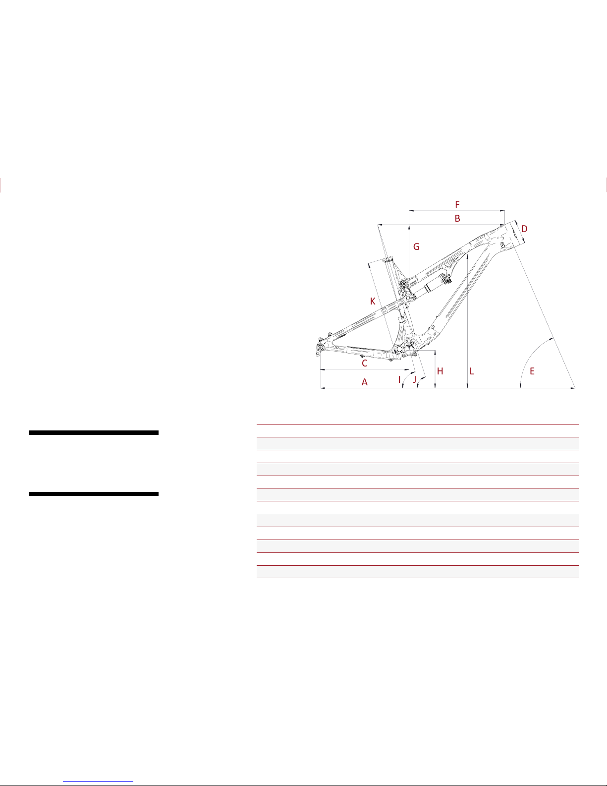
Geometry
C
A
B
F
E
D
G
H L
K
I J
GEOMETRY NOTEs
GEOMETRY TAKEN AT TOP OUT WITH 519MM
FORK LENGTH AND 42MM FORK OFFSET.
Component spec NOTE
the spid er 275 boost is d esigned aroun d
the use of single or double chain ring
sets only. Use of a triple ring set will
not allow proper clearance with the
frame.
SMALL MEDIUM LARGE XLARGE
A Wheel Base: 1125 mm/ 44.3” 1152 mm/ 45.4” 1178 mm/ 46.4” 1203 mm/ 47.4”
B Top Tube Length: 572 mm/ 22.5” 597 mm/ 23.5” 622 mm/ 24.5” 648 mm/ 25.5”
C Chain Stay Length: 419 mm/ 16.5” 419 mm/ 16.5” 419 mm/ 16.5” 419 mm/ 16.5”
D Head Tube Length: 102 mm/ 4” 115 mm/ 4.5” 127 mm/ 5” 127 mm/ 5”
E Head Tube Angle: 67˚ 67˚ 67˚ 67˚
F Reach: 422 mm/ 16.6” 445 mm/ 17.5” 467 m m/ 18.4” 492 mm/ 19.4”
G Stack: 579 mm/ 22.8” 591 mm / 23.25” 602 mm/ 23.7” 602 mm/ 23.7”
H BB Height: 337 mm/ 13.25” 337 mm/ 13.25” 337 mm/ 13.25” 337 mm/ 13.25”
I Sea t Tube Angle (Effective): 75.5˚ 75.5˚ 75.5˚ 75.5˚
J Seat Tube Angle (Actual): 72.5˚ 72.5˚ 72.5˚ 72.5˚
K Seat Tube Length: 375 m m/ 14.75” 445 mm/ 17.5” 483 m m/ 19” 514 mm/ 20.25”
L Standover Height: 781 mm/ 30.76” 790 mm/ 31.1” 797 mm/ 31.38” 796 mm/ 31.33”
6 // spider 275 Carbon boost
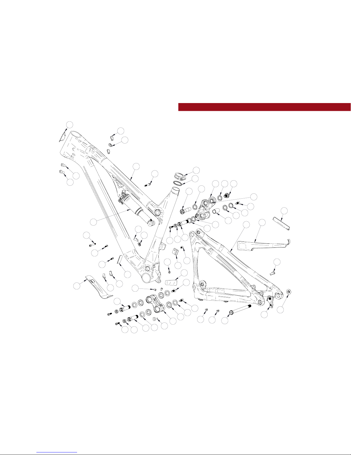
exploded view
and b.o.m.
22
19
36
37
3
30
7
30 8
38
32
31
12
1
26
13
10
5
9
25
14
6
4
29
6
17
15
35
19
23
28
27
24
19
11
39
11
11
21
21
33
17
24
19
18
30
19
18
25
14
5
17
30
19
34
20
2
16
19

INTENSE CYCLES // 7
ITEM
NO.
ITEM
PART
NUMBER
DESCRIPTION Q TY. TORQUE SPEC.
1
Derailleur Mount
Cover
130209 For Single Ring Setip 1 N /A
2
Crush Tube 130759 Top Link Bearing Crush Tube 1 N/A
3
Top Link 130762 Forged Top Link 1 N /A
3
Top Link 130760 Carbon Top Link 1 N/A
4
Box Link 130764 Forged Lower Link 1 N/A
5
Bearing Cap 130765 Top Link Bearing Cap 2 N /A
6
Bearing Cap 130778 Box Link Bearing Cap 4 N /A
7
Axle Upper 130780 Top Link Pivot Axle 1
20 Nm /
175 in-lbs
8
Bolt Shoulder 130785 Top Link Pivot Bolt 1
20 Nm /
175 in-lbs
9
Spacer 130789 Top Link Pivot Upper Sp acer 2 N /A
10
Hanger 130790 Forged Derailleur Hanger 1 N /A
11
Bolt Main Pivot 130791
Bolt Main Pivot 1.5t
Expander Blk
3
7 Nm /
60 in-lbs
12
Hanger Bolt 130792 Derailleur Hanger Bolt 1
11 Nm /
100 in-lbs
13
Rear Axle 130799
Axle Rear 148 x 12mm Boost
Wheel Axle Kit
1
11 Nm /
100 in-lbs
14
Cone Adjuster 130807 Box Link Expander Cone 3 N/A
15
Bumper 140006 Box Link Bum per 1 N /A
16
O-Ring 14 0013 Seat Collar Seal 1 N/A
17
Plug 140038 Top Link & Box Link Pivot Plug 3 N /A
18
Cable Guide Plug 140039 Cable Guide Plug 2 N/A
19
Cable Guide 140040 Guide Cable 8 N/A
20
Grommet 140042
Chain Stay Cable Ho le Grommet,
10 mm OD x 6 mm ID
1 N/A
21
Clip 310001 Cable Guide Clip 2 N /A
22
Seat Collar 346941 B ol t-On, 36.1 1 N/A
ITEM
NO.
ITEM
PART
NUMBER
DESCRIPTION Q TY. TORQUE SPEC.
23
Zerk Fitting 401011 M6 x 1.0 2
5 Nm /
40 in-lbs
24
BHCS M5 X 12 410010
Bottle Mount Bolt,
Button Head, M5 X 12
2
6 Nm /
54 in-lbs
25
SHCS M6 x 22 410009
Cone Adjuster Bolt,
Socket Head, M6 x 22
3
14 Nm /
125 in-lbs
25
SHCS M6 x 22 410032
Cone Adjuster Bolt, Socket
Head, M6 x 22, Titanium
3
14 Nm /
125 in-lbs
26
FHCS M6 x 12 41003 7
Derailleur Mount Cover,
Flat Head , M6 x 12
1
7 Nm /
60 in-lbs
27
SHCS M6 x 40 410002 SHCS, Socket Head, M6 x 40 1
7 Nm /
60 in-lbs
27
SHCS M6 x 40 410050
SHCS, Socket Head,
M6 x 40, Titanium
1
7 Nm /
60 in-lbs
28
SHCS M6 x 45 410015 SHCS, Socket Head, M6 x 45 1
7 Nm /
60 in-lbs
28
SHCS M6 x 45 41 0051
SHCS, Socket Head, M6 x 45
Tit an iu m
1
7 Nm /
60 in-lbs
29
Bearing 7902 430007
15 x 28 x 7 2RS,
MAX Angular Contact Bearing
4 N /A
30
Bearing 6802 430008
15 x 24 x 5 2RS,
MAX Radia l Bearin g
4 N /A
31
Guard Fla ck CS 500253 Flack Guard S275C Chainstay 1 N /A
32
Guard Fla ck SS 500254 Flack Guard S275C Seatstay 1 N /A
33
Protector
Chainstay
500255 Chain Suck Protector 1 N /A
34
Guard Fla ck 500256 Fla ck Guard S275C Down Tube 1 N /A
35
Decal 500300 Decal California Bear 1 N /A
36
Head Badge 500335 Head Badge Flame Logo 1 N/A
37
Front Triangle Carbon, 4 Sizes 1 N /A
38
Rear Triangle Carbon 1 Size 1 N/A
39
Rear Shock Rear Shock, 7.875 x 2 1 N/A
(sl)
(sl)
(sl)
(sl)

8 // spider 275 Carbon boost
Assembly
Tools needed
• High Grade, waterproof grease
(Maxima Waterproof Grease
recommended)
• Blue Loctite #243
• 5mm HEX wrench x2
• 8mm HEX wrench
Recommendation
use Grease on lower linkage bolts
only. use loctite on upper linkage
bolts, dropout bolts and hanger bolt.
PRE F A C E //
Service and maintenance on an Intense bicycle requires special tools, abilities and
knowledge of working on bicycles. It is always recommended to use an authorized
Intense dealer for service and maintenance. Always wear eye protection. It is critical
to use the proper tools, loctite, grease and torque specs during assembly. Failure to
follow these instructions may result in serious bodily injury or death.

INTENSE CYCLES // 9
1 4 5
2
3
CONNECTING TOP LINK TO FRONT TRIANGLE //
A Holding top link (#130760) with shock
mount pointed forward, hold upper spacer
(#130789) against inside of bearing race
(IMA GE #1).
B Match upper link to top tube, making
sure that spacers do not fall out.
C Using upper pivot axle (#130780), insert
through non-drive side of top link bearing and
push through to drive side bearing, making
sure spacers do not fall out (IMAGE #2).
Install shoulder bolt (#130785) into drive
side of top link pivot, and tighten to 20
NM or 175 in/lbs (IMAGE #3).
CONNECTING BOX LINK TO FRONT TRIANGLE //
A Hold bearing caps with rounded ends
facing outwards against bearings on
box link (IMAGE #4), (note box link
orientation in image #4, with rubber
bumper facing downward and rearward
on box link).
B Match link to front triangle and from
non drive side, insert greased main pivot
bolt (#130791) through the non-drive
side of frame (IMAGE #5).
C Use 8mm HEX to install, then torque
pivot bolt (#130791) to 7 NM or 60 in/lbs.

10 // spider 275 Carbon boost
7
6
8
9
CONNECTING REAR TRIANGLE
TO BOX LINK //
A Follow previous step to connect rear
triangle to box link (IMAGES #6 & 7).
B Use 8mm HEX to install, then torque
pivot bolt (#130791) to 7 NM or 60 in/lbs.
CONNECTING REAR TRIANGLE
TO TOP LINK //
A Holding spacers (#130765) with squared
edges against the bearing and the rounded
side facing outward (IMAGE #8), Swing
the seat stays up and align with the lower
spacers. From the non drive side of top
link, install greased pivot bolt (#130791)
(IMAGE #9). Use an 8mm HEX to install.
B Use an 8mm HEX to install torque main
pivot bolt (#130791) to 7 NM or 60 in/lb

INTENSE CYCLES // 1 1
TIGHTENING SEATSTAYS TO TOP LINK //
A Grease and install adjuster cone
(#130807) into head of main pivot bolt
(#130791) and greased M6x22mm bolt
(#410032) through the adjuster cone
into the main pivot bolt (IMAGE #14).
B Using hand pressure, squeeze the top
of seat stay together at the lower top
link location to eliminate side to side
play (IMAGE #15) then use a 5mm HEX
to make snug.
C Torque M6x22mm (#410032) to 14 NM
or 125 in/lbs (IMAGE #16).
INSTALLING REAR SHOCK //
A Holding rear shock match forward end to forward shock mount, and install greased
M6x40mm bolt (#410050) through drive side of frame (IMAGE #10). Do not tighten.
B Match rear end of shock to desired travel setting (see below) on upper link and
install greased M6x45mm bolt (#410051) through non-drive side of link (IMAGE #11).
C Torque shock bolts (#410050 & #410051) to 7 NM or 60 in/lbs (IMAGES #12 & 13).
adjustable travel NOTE
the top link of the spider 275 carbon boost features dual mounting p ositions. The
Upper shock mounting hole on top link is for LONG travel, the lower hole is for
SHORT travel. for more information see the set up guide on page 14.
1510 12
14 1611 13

12 // spider 275 Carbon boost
INSTALLING ADJUSTER CONES ON LOWER LINK //
A Grease and install adjuster cone
(#130807) into head of main pivot bolt
(#130791) and greased M6x22mm bolt
(#410032) through the adjuster cone into
the main pivot bolt (IMAGES #17 & 18).
B Torque M6x22mm (#410032) to 14 NM
or 125 in/lbs (IMAGE #19).
INSTALLING DERAILLEUR HANGER //
A Grease outer edges of derailleur
hanger (#130790) and loctite derailleur
bolt (#130792) if not pre loctite applied
(IMAGE #20).
B Insert hanger (#130790) into back of
frame opening and match derailleur bolt
(#130792) on the front side threading
bolt into hanger (IMAGE #21).
C Torque derailleur bolt to 11NM or 100 in/
lbs (IMAGE# 22).
2017
19 222118

torque
Achieving proper torque is vital to
ensuring the safe performance and
function of the spider 275 carbon
boost frame. Failure to do so could
result in sub-optimal performance of
your frame as well as premature wear
and tear of individual parts.
additional reference
In addition to this chart, all torque
values are laser etched onto
corresponding hardware for your
reference.
INTENSE CYCLES // 1 3
torque chart
20 Nm / 175 in-lbs
7 Nm / 60 in-lbs
7 Nm / 60 in-lbs
M8 HEX 7 Nm / 60 in-lbs
M5 HEX 14 Nm / 125 in-lbs
M8 HEX 7 Nm / 60 in-lbs
M5 HEX 14 Nm / 125 in-lbs
M8 HEX 7 Nm / 60 in-lbs
M5 HEX 14 Nm / 125 in-lbs
11 Nm / 100 in-lbs

seatp ost
make sure to insert seat post at lea st
4” into the main frame. Anything less
than this amount could cause damage
to the frame or even failure.
14 // spider 275 Carbon boost
set up
adjustable travel
upper mount: 130mm
lower mount: 115mm
upper mount
lower mount
4”

INTENSE CYCLES // 1 5
shock setup
rock shox monarch rt3 200x50mm
set up and tune
proper set up and tuning can vary
from shock to shock. Please consult
the rockshox manual included with
your bike for complete information
about set up, tuning and general
maintenance or visit www.sram.com/
rockshox/products
Trav el 115 mm 130 mm
Shock Stoke
50 mm
Shock Sag
30% when sitting on the bike
Fork Sag
25-30% when sitting on the bike
SHOCK
Rock Shox Monarch RT3 200x50mm
RIDER WEIGHT(LBS/KGS)
SPRING (PSI) REBOUND (clicks out) SPRING (PSI) REBOUND (clicks out)
100 lb s/ 45 kgs
92
2 to 3
99
2 to 3
110 lb s/ 50 kgs
98 107
120 lb s/ 54 kgs
104 114
130 lb s/ 59 kgs
110 122
140 l bs/ 63.5 kgs
116 129
150 lbs / 68 kgs 122
3 to 4
137
3 to 4
160 lbs / 72.57 kgs 128 145
170 lbs / 77.11 kgs 133 152
180 lbs / 81.65 kgs 139 160
190 lbs / 86.18 kgs 145 167
200 lbs / 90.72 kgs 151 175
210 lbs / 95.25 kgs 157 182
220 lbs / 99.79 kgs 163 190
230 lbs / 140.33 kgs 169
5 to 6
197
5 to 6
240 lbs / 108.86 kgs 174 205
250 lbs / 113.40 kgs 180 212
260 lbs / 117.93 kgs 186 220
270 lbs / 122.50 kgs 192 227
280 lbs / 127.00 kgs 198 235
290 lbs / 131.54 kgs 204 242
300 lbs / 136.08 kgs 210 250

16 // spider 275 Carbon boost
shock setup
x-fusion 02 rl 200x50mm
set up and tune
prope r set up and tun ing can vary from
shock to shock. Please consult the
X-Fusion manual included with your
bike for complete information about
set up, tuning a nd general ma intenance
or visit www.xfusionshox.com
Trav el 115 mm 130 mm
Shock Stoke
50 mm
Shock Sag
30% when sitting on the bike
Fork Sag
25-30% when sitting on the bike
SHOCK
X-Fusion 02 RL 200x50m m
RIDER WEIGHT(LBS/KGS)
SPRING (PSI) REBOUND (clicks out) SPRING (PSI) REBOUND (clicks out)
100 lb s/ 45 kgs
42
2 to 3
54
2 to 3
110 lb s/ 50 kgs
50 63
120 lb s/ 54 kgs
58 71
130 lb s/ 59 kgs
66 80
140 l bs/ 63.5 kgs
74 89
150 lbs / 68 kgs 82
4 to 5
97
4 to 5
160 lbs / 72.57 kgs 90 106
170 lbs / 77.11 kgs 98 114
180 lbs / 81.65 kgs 106 123
190 lbs / 86.18 kgs 113 131
200 lbs / 90.72 kgs 121 14 0
210 lbs / 95.25 kgs 129 148
220 lbs / 99.79 kgs 137 157
230 lbs / 140.33 kgs 145
6 to 7
165
6 to 7
240 lbs / 108.86 kgs 153 174
250 lbs / 113.40 kgs 161 182
260 lbs / 117.93 kgs 169 191
270 lbs / 122.50 kgs 177 199
280 lbs / 127.00 kgs 184 208
290 lbs / 131.54 kgs 192 217
300 lbs / 136.08 kgs 200 225

INTENSE CYCLES // 1 7

18 // spider 275 Carbon boost
maintenance
GENERAL SERVICE AND CARE //
You have purchased a high performance bicycle which requires a certain level of service
and maintenance to sustain the level of performance your frame was designed around.
Proper care will also ensure the bike is safe to ride at all levels. It is important to read
and understand the carbon care information as well as follow the maintenance schedule
and inspect your bicycle before each ride. These will not only help to limit or avoid costly
repairs but will also help to avoid injury due to service neglect and component failure.
carbon care
Intense Cycles employs advanced composite techniques and materials in
our frames which do require a certain level of care and maintenance to
ensure a safe experience at the high level of performance each frame is
designed around. Not following these guidelines will decrease the level
of performance and possibly cause injury or death.
• Use a soft cloth with warm soapy water to clean the carbon surfaces. Do
not use abrasive cloths or cleaners.
• Be sure all frame surfaces in contact with cables are protected. Cable
housing rubbing on carbon can wear over time.
• Be sure brake levers, handle bar ends and the fork crown do not contact
the frame at full rotation.
• Never clamp any part of a carbon frame in a bike stand or car rack.
• Always inspect your frame if you experience any chain suck. Intense
frames come equipped with steel chain suck plates but damage can still
be done in the event of chain suck.
• Always inspect your frame in full after a crash to be sure there is no
damage. Look for cracks, dents or loose fibers. If you discover damage
in any degree it’s best to have your frame inspected by a qualified
Intense Cycles dealer. Any direct impact to the frame can cause serious
structural damage.
• Use high grade waterproof grease on seat post, BB and head set bearing
contact areas with the carbon.
• Never ream or face a carbon frame.
• Be sure to follow all recommended torque settings.

INTENSE CYCLES // 1 9
maintenance Schedule*
Action Every Ride
500 Mil es or
1 Month
2000 Mi les or 6
Months
4000 Miles or
1 Year
Tires
Check air press ure, ins pect tread and sidewalls for tears a nd punc tures X
Chain
Brush off and lubricate X
Brakes
Squeeze brakes and confirm function X
General
Clean co mplete bike of mud and debris X
Headset
Check adjustment X
Box Lin k
Add grea se thru zerk fittings X
Frame Pivots
Check torques X
Spokes
Inspect for damage, check tension X
Shock a nd Fork
Check air press ure, ins pect for leaks X
Deraileur Cables
Inspect and lube X
Seat post
Clean and regrease interface with frame X
Frame Pivots
Remove pivot bolt s, check bearings for pitting and wear X
Headset
Disass emble stem, headset and fork. Check bearings for pitting an d wear X
Hubs
Pull whe els off, chec k hub bearings for pitting and wear X
Bottom Bracket
Remove crank arms and check BB bearings for pitting a nd wear X
Brakes
Replace brake pads X
Chain
Inspe ct for dam age and ch eck for stretchin g X
General
Complete Tune-Up X
Shock a nd Fork
Overhaul See MFG Recommendations
* THE ABOVE MAINTENANCE SCHEDULE IS ONLY A GUIDELINE. refer to COMPONENT MANUFACTURER FOR SPECIFIC INSTRUCTION ON MAINTAINING THEIR PARTS.

phone: (951)-296-9596
Customer Service: cs@intensecycles.com
General Info: info@intensecycles.com
Media, Marketing, Sponsorship: marketing@intensecycles.com
Intense Cycles USA 42380 rio nedo Temecula, Ca. 92590
www.I NTENSeCYCLES.com
330016
 Loading...