

user manual m16

AT INTENSE, WE HAVE ONE GOAL - TO PROVIDE THE RIDE OF YOUR LIFE.
Our team of designers, engineers and product experts are focused on one thing every
day: your experience on the bike. We build bikes that are as thrilling to look at as they
are to ride, and we build them for the select few of you who understand the difference
and refuse to settle for anything else.
From the early days of Intense, when founder Jeff Steber worked alone in his garage to
today, where a crew of talented people work in a Temecula, CA factory, Intense has been
a brand built on passion by forward thinkers who, even today, love nothing more than
to throw a leg over a sweet bike and head out for a rip. We’re so glad you’ve joined us.
Welcome to Intense, enjoy your experience.
THE M16
We haven’t forgotten our heritage… Introducing the all new, M16 DH. Made strictly for
downhill racing, this new aluminum frame features 27.5” wheels, race specific geometry,
adjustable travel and adjustable shock curve progression to fine tune the performance
for any trail. Couple that with a tapered head and steer tube, Patented VPP suspension
technology and extra wide 157mm rear wheel spacing to give you a solid race bike
that’s going to respond in the most demanding World Cup courses.
Welcome to
the family
2 // m16 user Manual

introduction 2
frame features / component spec 4
Geometry 5
exploded view and b.o.m. 6
Assembly 8
torque chart 14
setup 16
maintenance 18
registration
WWW.INTENSECYCLES.COM/WARRANTY-CARD/
contact customer service
cs@intensecycles.com
951-296-9596
INTENSE CYCLES // 3

Frame features //
• Adjustable travel – 8.5” or 9.5” (215mm or 241mm)
• adjustable shock curve progression
• 27.5" wheel size
• Patented VPP Suspension Technology
• Tapered Head Tube
• ISCG 05 Mounts
• Modern DH Race Geometry
• Integrated 157X12 dropouts
• External Cable Routing System
• Angular Contact Bearing / Collet 15MM Axle System with
replaceable Grease Zerks
• FLack GuaRD Chain stay & Down tube Protection
• Integrated fork bumper/cable guide system
Component spec //
• Fork – accepts 1.125" straight steer or 1.125"/1.5" tapered steer, 200mm Travel,
594mm lower leg length, 42mm offset
• Shock – 9.5” x 3”(241mm x 76mm), 22mm x 8mm and 34mm x 8mm reducers
• Chain Guide Mount - ISCG-05
• Seat post – 31.6mm
• Headset – zero stack 49 upper / 56 lower cups
• BOTTOM BRACKET - THREADED 83MM (M16)
• Rear Axle – 157mm x 12mm TA
• Brake Mount – international standard 160mm - 203mm rotor
4 // m16 user Manual
frame
features /
spec

INTENSE CYCLES // 5
Geometry
C
A
B
F
E
D
G
H
L
K
I
J
GEOMETRY NOTEs
GEOMETRY TAKEN AT TOP OUT WITH 594MM
FORK LENGTH AND 42MM FORK OFFSET.
Component spec NOTE
the m16 is designed around the use of
a single chain ring set only. Use of a
double or triple ring set will not allow
proper clearance with the frame.
SMALL MEDIUM LARGE XLarge
A
Wheel Base: 1194 mm/ 47” 1219 mm/ 48” 1245 mm/ 49” 1270 mm/ 50”
B
Top Tube Length: 565 mm/ 22.25” 591 mm/ 23.25” 616 mm/ 24.25” 641 mm/ 25.25”
C
Chain Stay Length: 445 mm/ 17.5” 445 mm/ 17.5” 445 mm/ 17.5” 445 mm/ 17.5”
D
Head Tube Length: 109 mm/ 4.3” 115 mm/ 4.5” 122 mm/ 4.8” 122 mm / 4.8”
E
Head Tube Angle: 63.5˚ 63.5˚ 63.5˚ 63.5˚
F
Reach: 391 mm/ 15.4” 413 mm/ 16.3” 436 mm / 17.15” 461 mm/ 18.15”
G
Stack: 587 mm/ 23.1” 592 mm / 23.3” 598 mm/ 23.55” 598 mm/ 23.55”
H
BB Height: 365 mm/ 14.375” 365 mm/ 14.375” 365 mm/ 14.375” 365 mm/ 14.375”
I
Seat Tube Angle (Effective): 73.3˚ 73.3˚ 73.3˚ 73.3˚
J
Seat Tube Angle (Actual): 59.5˚ 59.5˚ 59.5˚ 59.5˚
K
Seat Tube Length: 436 mm/ 17.2” 442 mm/ 17.4” 454 mm/ 17.9” 454 mm/ 17.9”
L
Standover Height: 797 mm/ 31.4” 803 m m/ 31.6” 809 mm/ 31.9” 816 mm/ 32.1”

6 // m16 user Manual
exploded view
and b.o.m.
26
17
17
21
3
11 4 20
28
1
28
4
13
25
3
10
9
12
37
20
19
24
33
26
17
17
14
34
15
17
17
35
18
29
29
36
6
8
2
17
16
27
27
30
32
31
22
22
22
22
7
7
7
5
23

INTENSE CYCLES // 7
ITEM PART NUMBER DESCRIPTION FR AME SIZE USE D ON
Shock
370335 Shock CCDB-C M16, 240 x 76 x 350 Small
Shock
370336 Shock CCDB-C M16, 240 x 76 x 400 Medium
Shock
370337 Shock CCDB-C M16, 240 x 76 x 450 Large
ITEM
NO.
ITEM
PART
NUMBER
DESCRIPTION Q TY. TORQUE SPEC.
1
Box Link 130214 Forged Lowe r Link 1 N /A
2
Top Link 130215 Forged Top Lin k 1 N/A
3
Cone Adjuster 130777 Expander Cone 3 N/A
4
Bearing Cap 130778 Main Pivo t Bearing Cap 4 N/A
5
Axle Upper 130780 Top Link Pivot Axle 1
20 Nm /
175 in-lbs
6
Washer 130784 Top Link Pivot, Lower Washer 2 N/A
7
Bolt Shoulder 130785 Top Link Pivot B olt 3
20 Nm /
175 in-lbs
8
Spacer 130789 Top Link Pivot, Upper Spacer 2 N /A
9
Hanger 130790 Forged Derailleur Hanger 1 N /A
10
Rear Axle 130794 157 x 12mm Axle 1
11 Nm /
100 in-lbs
11
Bolt Main
Pivot
130795 Main Pivot 1.5T Expander Bolt 2
7 Nm /
60 in-lbs
12
Hanger Bolt 130798 Rear Derailleur Hanger B olt 1
11 Nm /
100 in-lbs
13
Plug 140004 Box Link Pivot Plug 2 N /A
14
Bumper 140009 Fork Bumper Left 1 N/A
15
Bumper 140010 Fork Bumper Right 1 N /A
16
Fender 140011 Rear Wheel Fende r 1 N/A
17
Clip Plastic 310001 Sna p-on Cable Guide Single 9 N /A
18
Seat Collar 346941 Bolt-o n 3 6.1 1 N /A
19
M8 Nut 400005 Shock Bolt Nyloc Nut 1
16 Nm /
140 i n-lbs
20
Zerk Fitting 401011 M6 x 1.0 2
5 Nm /
40 in-lbs
21
SHCS
M6 x 22
410009
Cone Adjuster Bolt, Socke t Head,
M6 x 22
2
14 Nm /
125 in-lbs
ITEM
NO.
ITEM
PART
NUMBER
DESCRIPTION Q TY. TORQUE SPEC.
22
BHCS
M5 X 12
410010
Guide Bo lt, Button Head,
M5 X 12
4
6 Nm /
54 in-lbs
23
SHCS
M8 x 60
410012
Shock Bolt Socket Head,
M5 X 12
1
16 Nm /
140 i n-lbs
24
SHCS
M8 x 35
410038
Shock Bolt, Socket Head,
M8 x 35
1
16 Nm /
140 i n-lbs
25
SHCS
M6 x 25
410039
Cone Adjuster Bolt, Socke t Head,
M6 x 25
1
14 Nm /
125 in-lbs
26
M8 Washer 420004 Shock Bolt Washer 2 N/A
27
Bearing 6901 430001 12 x 24 x 6 2RS Radial Bearing 2 N/A
28
Bearing 7902 430007
15 x 28 x 7 2RS
MAX Angular Contact Bearing
4 N/A
29
Bearing 6802 430008
15 x 24 x 5 2RS
MAX Radia l Bearing
2 N/A
30
Guard Fla ck SS 500235 Flack Guard, M16 Seat Stay 1 N /A
31
Guard Fla ck
DT
500236 Flack Guard, M16 Down Tube 1 N/A
32
Guard Fla ck CS 500238 Flack Guard, M16 Chain Stay 1 N /A
33
Decal 500300 Decal California Bear 1 N/A
34
Head Badge 500337 M16 Head Badge 1 N/A
35
Front Triangle Aluminum, 3 sizes 1 N/A
36
Rear Triangle Aluminum, 1 Size 1 N /A
37
Rear Shock 240mm x 76mm 1 N /A

8 // m16 user Manual
Assembly
Tools needed
• High Grade, waterproof grease
(Maxima Waterproof Grease
recommended)
• Blue Loctite #243
• 5mm HEX wrench x2
• 6mm hex wrench
• 8mm HEX wrench
Recommendation
use Grease on lower linkage bolts
only. use loctite on upper linkage
bolts, dropout bolts and hanger bolt.
PR E F A CE //
Service and maintenance on an Intense bicycle requires special tools, abilities and
knowledge of working on bicycles. It is always recommended to use an authorized
Intense dealer for service and maintenance. Always wear eye protection. It is critical
to use the proper tools, loctite, grease and torque specs during assembly. Failure to
follow these instructions may result in serious bodily injury or death.

INTENSE CYCLES // 9
CONNECTING TOP LINK TO FRONT TRIANGLE //
A Holding narrow end of top link
(PART#130215); hold upper spacer
(PART#130789) against inside of bearing
race. Match upper linkage to pivot point
on front triangle, making sure that
spacers do not fall out (IMAGE #1). See
exploded view for linkage orientation.
B Using upper pivot axle (PART
#130780), insert through left (non-drive)
side of top link, making sure spacers do
not fall out. Thread shoulder bolt (PART
# 130785) into upper pivot axle from
opposite side of top link (IMAGE #2).
C Holding 5mm allen wrench on non-
drive side upper pivot axle, insert torque
wrench into shoulder bolt on drive side
and tighten to 175 in/lb (IMAGE #3).
CONNECTING BOX LINK TO FRONT TRIANGLE //
A Hold bearing cap (PART #130778) with
rounded edge facing outwards against
bearings pressed into box link (PART
#1 3 0 2 14) ( I M AGE #4).
B Match box link (PART # 130214) to
front triangle pivot point and insert main
pivot expander bolt (PART #130795)
with greased threads through non-drive
side of box link, holding bearing caps in
place (IMAGE #5).
C Use 8mm allen to thread main pivot
expander bolt into box link, and torque
to 60 in/lb (IMAGE #6).
1 4
2 5
3 6

10 // m16 user Manual
CONNECTING REAR TRIANGLE TO BOX LINK //
A Follow previous steps to connect rear triangle to box link (IMAGES #7-9).
INSTALLING ADJUSTER CONES //
A Grease and insert cone adjuster
(PART #130777) into head of main
pivot expander bolt (PART #130795)
with M6x22mm bolt (PART #410009)
inserted through cone adjuster (IMAGE
#10 & #11).
B Tighten M6x22mm bolt (PART
#410009) with 5mm allen and torque
to 125 in/lb (IMAGE #12).
7
8 9
10
1211

INTENSE CYCLES // 1 1
CONNECTING REAR TRIANGLE TO TOP LINK //
A Hold washer (PART #130784) against
inside of lower top link mount, then bring
rear triangle forward matching upper
pivot point to top link (IMAGE #13).
B Match shoulder bolts (PART #130785)
to top link and insert through linkage,
threading bolts into the rear triangle
while holding washer is in place between
bearing and linkage (IMAGE #14 & #15).
c Tighten shoulder bolts to 175 in/lb
(IMAGE #16).
INSTALLING REAR SHOCK //
A Holding rear shock with reservoir above
and forward, insert into frame with lower
eyelet towards shock mount on box link,
then bring forward shock eyelet to
forward shock mount (IMAGE #17 & #18).
B Install forward M8x60mm shock
mount bolt (#410012) with 8mm washer
(#420004) on bolt head through drive
side of frame to the desired progression
setting (IMAGE #19).
1713 15
191814 16
Shock curve progression
upper mount: more progressive
lower mount: less progressive

12 // m16 user Manual
INSTALLING REAR SHOCK (CON'T) //
C Match second 8mm washer (PART
#420004) to threads on non-drive side
of forward shock mount bolt (PART
#410013), then thread 8mm nut (PART
#400005) on to forward shock mount
bolt (IMAGE #20 & # 21).
d Hold nut with 8mm wrench and tighten
opposite side with 6mm allen to 140 in/
lb (IMAGE #22).
e Match rear eyelet of shock to box link shock mount and thread bolt through top link
at desired travel setting. Tighten with 6mm allen to 140 in/lb (IMAGE #23 & #24).
20
24232221
adjustable travel
the box link shock mount features
dual mounting positions which allow
you to choose between 215mm and
241mm of rear travel.
upper mount: 215mm
lower mount: 241mm

INTENSE CYCLES // 1 3
INSTALLING DERAILLEUR HANGER //
A Grease outer edges of derailleur hanger
(#130790) and insert into frame from
inside of rear triangle, matching hanger
bolt (PART #130798) to hanger threads
from the outside of the frame (IMAGE #25).
B Tighten hanger bolt using 6mm allen
to 100 in/lb (IMAGE #26).
REAR AXLE INSTALLATION //
A The M16 uses a rear axle with an
expanding collet system similar to our
main pivot bolts. This ensures a secure
fit between the axle and frame. To install
rear axle, insert threaded end of axle
through non-drive side dropout until it
reaches female threaded end of hanger.
You can then insert a 5mm allen through
opening on the hanger bolt, which will
allow you to tighten axle in a counterclockwise (rearward) direction to 100
in/lb. You may then grease and install
the cone adjuster into the opening on
the non-drive side of the axle, then
insert M6x25mm bolt into cone adjuster
and tighten to 125 in/lb (AXLE IMAGES
#27-29).
25
26 27
28
29
torque
Achieving proper torque is vital to
ensuring the safe performance and
function of the m16 frame. Failure
to do so could result in sub-optimal
performance of your frame as well as
premature wear and tear of individual
parts.
additional reference
In addition to this chart, all torque
values are laser etched onto
corresponding hardware for your
reference.
14 // m16 user Manual
torque chart
20 Nm / 175 in-lbs
16 Nm / 140 in-lbs
20 Nm / 175 in-lbs
16 Nm / 140 in-lbs
6 Nm / 54 in-lbs
M8 HEX 7 Nm / 60 in-lbs
M6 HEX 14 Nm / 125 in-lbs
M8 HEX 7 Nm / 60 in-lbs
M6 HEX 14 Nm / 125 in-lbs
Rear Axle 11 Nm / 100 in-lbs
M6 HEX 14 Nm / 125 in-lbs

INTENSE CYCLES // 1 5
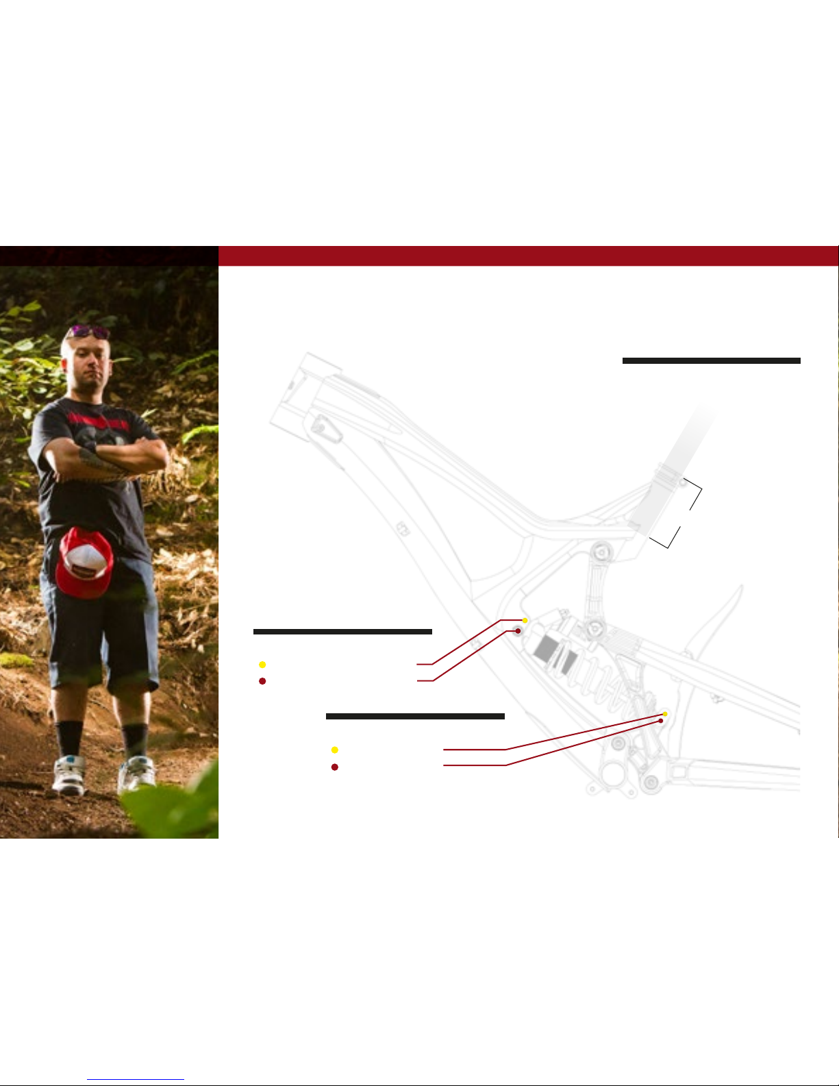
set up
4”
Shock curve progression
upper mount: more progressive
lower mount: less progressive
adjustable travel
seatpost
make sure to insert seat post at le ast
4” into the main frame. Anything less
than this amount coul d cause damage
to the frame or even failure.
upper mount: 215mm
lower mount: 241mm

INTENSE CYCLES // 1 7
shock setup
cane creek db coil 241 x 76mm (9.5" x 3.0")
set up and tune
proper set up and tuning can
vary from shock to shock. Please
consult the cane creek manual
included with your bike for complete
information about set up, tuning
and general maintenance or visit
www.canecreek.com/products/
suspension
note
coil springs stocked in 50 lb.
increments from 350 to 500
trav el
216 mm (8. 5")
trav el
241 mm (9.5 ")
RIDER WEIGHT
(LB S/KGS)
SPRING WEIGHT
(LB S)
RIDER WEIGHT
(LB S/KGS)
140 l bs / 64 kgs
350
140 l bs / 64 kgs
150 lb s / 68 kgs 150 lb s / 68 kgs
160 lb s / 73 kgs 160 lb s / 73 kgs
170 lbs / 77 kgs 1 70 lbs / 77 kgs
180 lb s / 82 kgs
400
180 lb s / 82 kgs
190 lb s / 86 kgs 190 lb s / 86 kgs
200 lbs / 91 kgs 200 lb s / 91 kgs
210 lb s / 95 kgs
450
210 lb s / 95 kgs
220 lbs / 1 00 kgs 220 lbs / 1 00 kgs
230 lbs / 104 kgs
500
230 lbs / 104 kgs
240 lbs / 1 09 kgs 240 lbs / 109 kgs
250 lbs / 113 kgs 250 lbs / 113 kgs
260 lbs / 118 kgs 260 lbs / 118 kgs
270 lb s / 122 kgs 270 lb s / 122 kgs
Shock Sag
35% when sitting on the bike
shock stroke
76 mm (3.0")
Fork Sag
25-30% when sitting on the bike

18 // m16 user Manual
maintenance
GENERAL SERVICE AND CARE //
You have purchased a high performance bicycle which requires a certain level of service
and maintenance to sustain the level of performance your frame was designed around.
Proper care will ensure the bike is safe to ride at all levels. It is important to follow
the maintenance schedule and inspect your bicycle before each ride. These will not
only help to limit or avoid costly repairs but will also help to avoid injury due to service
neglect and component failure.

INTENSE CYCLES // 1 9
maintenance Schedule*
Action Every Ride
500 Mil es or
1 Month
2000 Mi les or 6
Months
4000 Miles or
1 Year
Tires
Check air pressure, in spect tread and sidewalls for tears and punctures X
Chain
Brush off and lub ricate X
Brakes
Squeeze brakes and confirm function X
General
Clean co mplete bike of mud and debris X
Headset
Check adjustment X
Box Lin k
Add grea se thru zerk fittings X
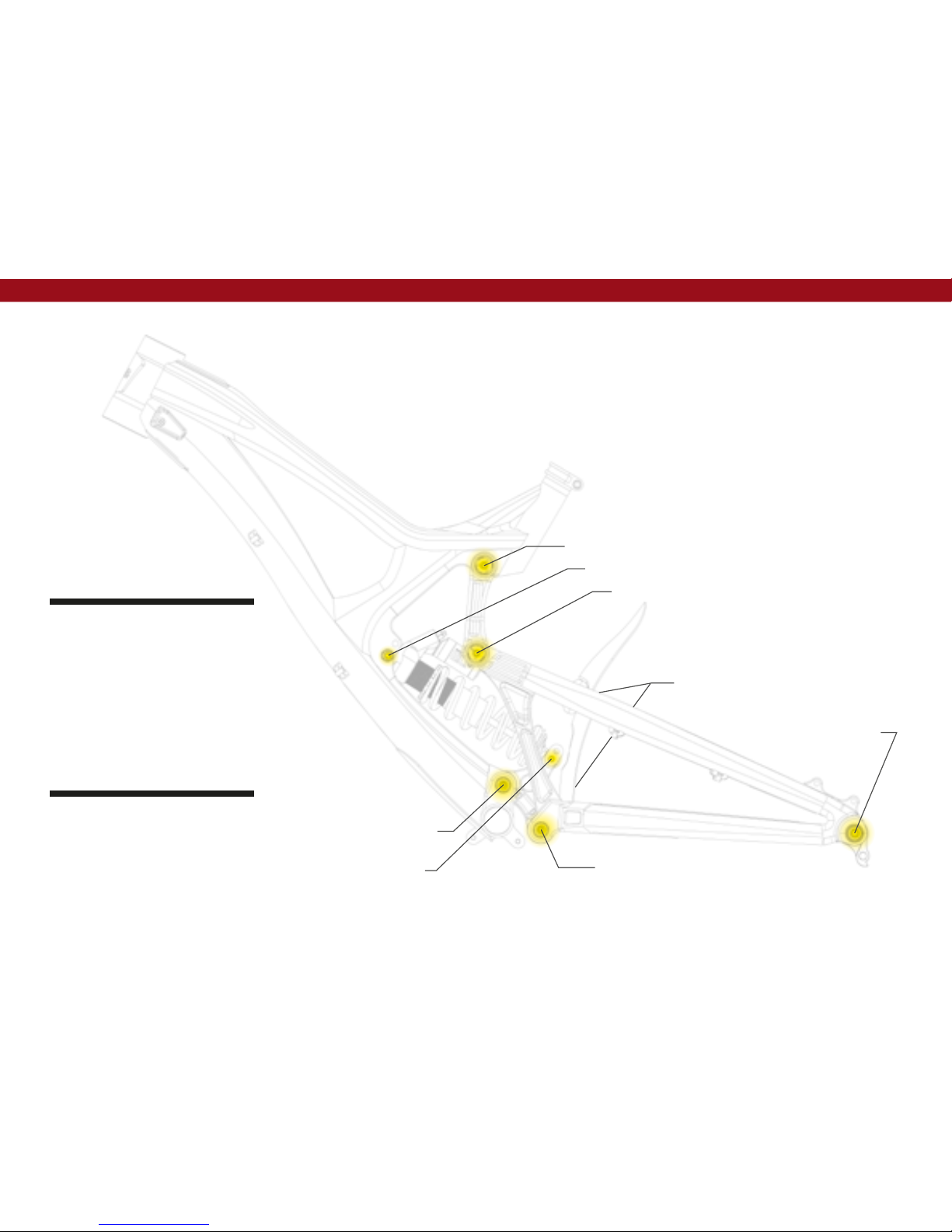
Frame Pivots
Check torques X
Spokes
Inspect for damage, check tension X
Shock a nd Fork
Check air pressure, in spect for leaks X
Deraileur Cables
Inspect and lube X
Seat post
Clean and regrease interface with frame X
Frame Pivots
Remove pivot bolts, check bearings for pitting and wear X
Headset
Disass embl e stem, headse t and fork. Check bearin gs for pitting and wear X
Hubs
Pull whe els off, check hub bearings for pitting and wear X
Bottom Bracket
Remove crank arms and check BB bearings for pitting and wear X
Brakes
Replace brake pa ds X
Chain
Inspe ct for damage and check for stretching X
General
Complete Tune-Up X
Shock a nd Fork
Overhaul See MFG Recommendations
* THE ABOVE MAINTENANCE SCHEDULE IS ONLY A GUIDELINE. refer to COMPONENT MANUFACTURER FOR SPECIFIC INSTRUCTION ON MAINTAINING THEIR PARTS.

phone: (951)-296-9596
Customer Service: cs@intensecycles.com
General Info: info@intensecycles.com
Media, Marketing, Sponsorship: marketing@intensecycles.com
Intense Cycles USA 42380 rio nedo Temecula, Ca. 92590
www.I NTENSeCYCLES.com
330013
 Loading...