


Installation
Guide
English Svenska Suomi Norsk
FG500 Fiber Residential Gateway
Installation
English Svenska Suomi Norsk
English
Guide
FG500 Fiber Residential Gateway
Language Page
English ....................... 4
Svenska ..................... 8
Suomi ...................... 12
Norsk ....................... 16
32
FG500
AR560
WLAN
LAN1
2
LAN3
4
LAN2
3
LAN4
5
6
8
79
1
USB
Fiber Residential Gateway
1
WPS
FG500
Fiber Residential Gateway
USB
USB
TEL1TEL2
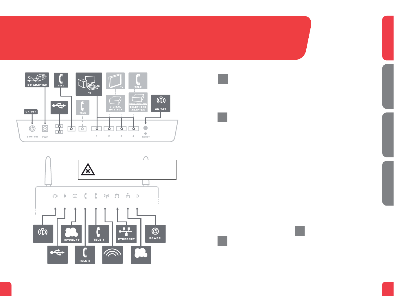
Back
Attention! This product contains a laser transmitter. Lasers
WPS USB Internet TEL2 TEL1 WiFi Ethernet WAN POWER
3
2 4
USB
can be harmful to the eyes. Therefore, the product should
be handled according to instructions. FG500 should only be
on (”ON”) when installed in the wall bracket/tray.
5
79
6
WIFI
Front/top
8
WAN
WPS
This installation guide will help you install the Inteno FG500, Fiber
a
Residential Gateway. Your service provider will supply you with
information about login.
Start Box
b
Check that the following items
are in the Start Box:
• Inteno FG500 Fiber Residential
Gateway
• Power adapter
• Network cable (white) (large connector)
• Two antennas for WiFi (wireless data
connection)
The product must be placed so that it has
adequate ventilation. The product must
not be covered or placed in a confined
space as it can lead to overheating. A
misplaced product can mean shortened
lifespan due to increased operating temperature. This may also affect the product
warranty.
Connecting the WAN
c
The WAN connection on the FG500 is a
fiber port on the bottom of the modem.
1. Remove the plastic cover which is
mounted on the fiber port on the
bottom of the modem.
2. The modem should be installed on the
wall bracket/tray mounted on the wall.
3. Remove the cover on the bracket by
moving it to the right.
4. A fiber connection is mounted in the
bracket. Remove the plastic covering
from the connector.
5. The bracket and the modem have three
(3) longitudinal mounting guides to
allow easy mounting of the modem to
the bracket.
6. Match the modem’s mounting guides
to the bracket and pull the modem to
the left.
7. The modem is now connected. If you
intend to use the wireless connection,
make sure you attach the two antennas
included in the start box.
Connecting the LAN
d
1. Connect the white network cable
between the FG500 network port (LAN
1-4) and the network port on the back
or side of your computer. NOTE! In
some cases, your broadband service
provider will instruct you to connect to
Fiber Residential Gateway
English Svenska Suomi Norsk
FG500
54

a specific network port (LAN 1-4). Verify
this in the documents and/or manual
you received from your service provider.
2. Finally, plug the power adapter into an
electrical outlet and the small connector
into the modem labelled “Power.”
3. The indicator lights will blink for roughly
30 seconds. If you have connected your
modem properly, the Power, WAN and
Internet indicator lights will be a fixed
green or yellow color. See picture labelled “Front.” You have now connected
the FG500.
Connecting the
e
Wireless Local Area
Network (WiFi)
1. For wireless connection first perform a
search for available wireless networks in
your computer.
2. Compare the list with the SSID which is
shown on a sticker placed on the bottom of the FG500.
3. Connect by clicking on the correct SSID
and then type in the encryption code
which is shown on the sticker labelled
WPA on the under side of the FG500.
Connecting your
f
digital TV Box for IPTV
1. A network cable was provided with
your digital TV Box. Connect it to the
network port (LAN 1-4). NOTE! In some
cases, your broadband service provider
will instruct you to connect to a specific
network port (LAN 1-4). Verify this in the
documents and/or manual you received
from your service provider.
2. Connect the other end of the network
cable to your digital TV Box for IPTV.
3. Start the digital TV Box for IPTV.
4. If a problem should occur during the
connection process, we recommend
that you contact your service provider.
Connecting
g
IP Telephony (VoIP)
1. Connect a telephone cable to the port
labeled TEL 1 on the FG500.
2. Connect the other end of the telephone
cable to your telephone. Alternatively,
follow the instructions from your service
provider.
3. Activate the telephony service according
to the instructions from your service
provider.
Description of
h
the front panel
From left to right
1. WPS
Off – WPS not activated
Blinking (green) – WPS activated
2. USB
On (green) – USB device detected
Off – No USB device detected
3. Internet
On (green) – IP-address received
On (red) – IP-adress not received
4. TEL 2
On (green) – Telephony service activated
Off – Telephony not service activated
Slow blinking (green) – Failed telephony
service activation
Fast blinking (green) – Incoming call
5. TEL 1
On (green) – Telephony service activated
Off – Telephony not service activated
Slow blinking (green) – Failed telephony
service activation
Fast blinking (green) – Incoming call
6. WiFi
On (green) – WIFI activated
Off – WIFI not activated
Blinking (green) – Activity
7. Ethernet
On (green) – LAN connected
Off – LAN not connected
Blinking (green) – Activity
8. WAN
On (green) – WAN connected
1000Mbps
Blinking (green) – Activity 1000Mbps
On (yellow) – WAN connected 100Mbps
Blinking (yellow) – Activity 100Mbps
Off – WAN not connected
9. Power
On (green) – Power on
On (red) – Start up failure (contact
service provider)
Off – Power off
Advanced network
i
administration
Check that the computer which is
connected to your modem has been
issued an automatic IP address between
192.168.1.2 and 192.168.1.254. You may
need to manually set the IP address.
For example: 192.168.1.23,
subnet mask: 255.255.255.0.
1. In your browser’s address line type
http://192.168.1.1
2. Login in using admin as user name and
admin as password
3. Select the function you want from the
modem’s menu on the left. Note that
network administration is only available
in the standard software. If your service
provider has their own software, this
function may be turned off or have only
limited function. Contact your service
provider for more information.
Troubleshooting
j
1. Is the power indicator light on modem
off? Check that the modem is properly connected to the power adapter.
Check that the power adapter is connected to an electrical outlet and that
the LED on the power adapter is lit. If
the LED on the power adapter is not
lit up this may indicate a faulty power
adapter. If the modem is properly
connected and the power adapter
is lit but the power indicator light on
the modem is still not lit up this may
indicate a faulty modem. Contact your
service provider.
2. Are the Power or Internet indicator
lights red? Contact your service
provider.
3. Is the WAN indicator light off? Check
the connection between the WAN port
on the modem and your broadband
outlet. If the WAN indicator light is off,
despite proper connection, contact
your service provider.
4. Is the Ethernet indicator light off?
Check the connection between the
LAN port on the modem and the
Network Interface Card (NIC) in your
computer. Check that the NIC in your
computer is functioning properly.
5. Reset button. See picture labeled
“Back.” This button resets the modem
to factory settings. Press it for 10
seconds.
English Svenska Suomi Norsk
FG500
Fiber Residential Gateway
Fiber Residential Gateway
FG500
76

FG500
AR560
WLAN
LAN1
2
LAN3
4
LAN2
3
LAN4
5
6
8
79
1
USB
Fiber Residential Gateway
1
FG500
Fiber Residential Gateway
8
WPS
USB
USB
TEL1TEL2
Baksida
Observera! Denna produkt innehåller lasersändare. Laser
WPS USB Internet TEL2 TEL1 WiFi Ethernet WAN POWER
3
2 4
USB
kan vara skadlig för ögonen. Därför ska produkten endast
hanteras enligt instruktion. FG500 ska endast vara påslagen
(”on”) när den är installerad i bottenplattan.
5
6
Framsida/topp
79
8
WIFI
WAN
WPS
Den här installationsguiden hjälper dig att installera Inteno FG500,
a
Fiber Residential Gateway. Information om hur du loggar in och
får åtkomst till dina tjänster får du från din operatör.
Startboxen
b
Kontrollera att följande finns
med i startboxen:
• Inteno FG500 Residential Gateway
• Strömadapter
• Nätverkskabel LAN (vit)
• Två antenner för WiFi (trådlös
dataanslutning)
Produkten måste placeras så att den
får god ventilation. Produkten får inte
övertäckas eller placeras i ett trångt
utrymme då det kan leda till överhettning. En felplacerad produkt kan innebära
förkortad livslängd på grund av förhöjd
arbetstemperatur. Detta kan även påverka
garantvillkoren.
Inkoppling WAN
c
FG500 har sin WAN-anslutning i form
av en fiberkontakt på undersidan av
modemet.
1. Avlägsna plastskyddet som sitter
monterad på WAN-kontakten under
modemet.
2. Modemet skall nu monteras på den
bottenplatta/vägfäste som sitter
monterad på er vägg i anslutning till
inkommande bredbandsfiber.
3. Avlägsna täcklocket på bottenplattan
genom att dra det till höger.
4. I bottenplattan sitter en fiberkontakt
monterad, avlägsna plastskyddet som
sitter monterad på kontakten.
5. Bottenplattan och modemet har tre (3)
längsgående monteringsguider för att
underlätta monteringen av modemet på
bottenplattan.
6. Passa in modemets monteringsguider
i bottenplattans monteringsguider och
drag modemet till vänster.
7. Modemet är nu inkopplat. Om du
avser att använda WiFi (trådlös dataanslutning) passa på att skruva på
medföljande antenner.
Inkoppling LAN
d
1. Koppla den vita nätverkskabeln mellan
FG500 nätverkskontakt (LAN1-4) och
nätverkskontakten på baksidan eller
sidan av din dator. OBS! I vissa fall
Fiber Residential Gateway
English Svenska Suomi Norsk
FG500
9

uppger din operatör att datorn skall
kopplas till en specifik nätverkskontakt
(LAN-1-4). Kontrollera detta i eventuellt
medföljande manual från din operatör.
2. Koppla slutligen in strömadaptern till
eluttaget och den andra änden i
kontakten på modemet märkt Power.
3. Lamporna på modemet kommer att
blinka i cirka 30 sekunder. Har du gjort
allting rätt så kommer lamporna Power,
WAN samt Internet lysa med fast grönt
eller gult sken på ditt modem, se bild
”Framsida/Topp” sid 8. Du är nu färdig
med inkopplingen av FG500.
Inkoppling av trådlös
e
data-anslutning (WiFi)
1. För trådlös dataanslutning gör först en
sökning efter trådlösa nätverk på din
dator.
2. Jämför i listan med det SSID som
anges på klisterlappen på undersidan
av FG500.
3. Anslut genom att dubbelklicka på rätt
SSID och därefter skriva in den krypteringsnyckel som anges på klisterlappen
märkt WPA på undersidan av FG500.
Inkoppling av digital-
f
tv-box för IPTV
1. Koppla nätverkskabeln som medföljer
digital-tv box för IPTV till nätverkskontakt (LAN-1-4). OBS! I vissa fall uppger
din operatör att digital-tv boxen skall
kopplas till en specifik nätverks-kontakt
(LAN-1-4). Kontrollera detta i eventuellt
medföljande manual från din operatör.
2. Koppla andra änden av nätverkskabeln
till din digital-tv box för IPTV.
3. Starta digital-tv boxen för IPTV.
4. Vid problem med inkoppling eller uppkoppling av din digital-tv box hänvisar vi
till din operatör.
Inkoppling av
g
IP-telefoni (VoIP)
1. Koppla en telefonkabel till kontakten
märkt TEL1 på FG500.
2. Koppla andra änden av telefonkabeln till
din telefon, alternativt följ inkopplingsinstruktionerna som medföljer från din
operatör.
3. Aktivera telefonitjänst enligt instruktioner
från din operatör.
Beskrivning av
h
frontpanelen
Från vänster till höger:
1. WPS
Släckt – WPS ej aktiv
Blinkande (grön) – WPS aktiverad
2. USB
Tänd (grön) – USB enhet detekterad
Släckt – Ingen USB enhet detekterad
3. Internet
Tänd (grön) – IP-adress mottagen
Tänd (röd) – IP-adress ej mottagen
4. TEL 2
Tänd (grön) – Telefonitjänst aktiveradSläckt – Telefonitjänst ej aktiverad
Långsamt blinkande (grön) – Problem
med aktivering telefonitjänst
Snabbt blinkande (grön) – Inkommande
samtal
5. TEL 1
Tänd (grön) – Telefonitjänst aktiverad
Släckt – Telefonitjänst ej aktiverad
Långsamt blinkande (grön) – Problem
med aktivering telefonitjänst
Snabbt blinkande (grön) – Inkommande
samtal
6. WiFi
Tänd (grön) – WIFI aktiverad
Släckt – WIFI ej aktiverad
Blinkar (grön) – Aktivitet
7. Ethernet
Tänd (grön) – LAN uppkopplad
Släckt – LAN ej uppkopplad
Blinkar (grön) – Aktivitet
8. WAN
Tänd (grön) – Uppkopplad med nätverket 1000Mbps
Blinkar (grön) – Aktivitet 1000Mbps
Tänd (gul) – Uppkopplad med nätverket 100Mbps
Blinkar (gul) – Aktivitet 100Mbps
Släckt – Ej uppkopplad med nätverket
9. Power
Tänd (grön) – Strömmen är på
Tänd (röd) – Uppstartsfel (kontakta din
operatör)
Släckt – Strömmen är av
Avancerad webb-
i
administration
Säkerställ att din dator som anslutits
till modemet får en automatiskt tilldelad
IP-adress mellan 192.168.1.2 och
192.168.1.254. Du kan behöva sätta
din IP-adress manuellt, exempelvis:
192.168.1.23, nätverksmask: 255.255.255.0.
1. Ange http://192.168.1.1 i din
webbläsares adressrad
2. I rutan för inloggning ange admin
som användarnamn och admin som
lösenord
3. Välj önskad funktion i modemets
menyrad till vänster. Observera att
webbadministration är tillgänglig
endast i standardmjukvara. Om din
operatör har en egen mjukvara kan
denna funktion vara avslagen eller
begränsad i funktionalitet. Fråga din
operatörs kundservice om ytterligare
information.
Felsökning
j
1. Är spänningslampan power släckt?
Kontrollera att modemet är ordentligt
ansluten till strömadapter. Kontrollera
att strömadapter är ansluten till ett
eluttag och att lampan på strömadapter lyser. Om lampan på strömadaptern
inte lyser kan detta tyda på en felaktig
strömadapter. Om modemet är korrekt
anslutet och nätadaptern lyser men
spänningslampan på modemet fortfarande inte lyser kan det tyda på ett
trasigt modem. Kontakta din operatör.
2. Lyser Power eller Internet-indikator
rött? Kontakta din operatör.
3. Är WAN-indikator släckt? Kontrollera
anslutningen mellan WAN-porten på
modemet och ditt bredbandsuttag.
Om WAN-indikator trots korrekt inkoppling
är släckt, kontakta din operatör
4. Är Ethernet-indikatorn släckt?
Kontrollera anslutningen mellan
LANporten på modemet och nätverkskortet i din dator. Kontrollera också att
nätverkskortet i din dator fungerar.
5. Resetknapp, se bild ”Baksida”, sid 8.
Med denna knapp återställer du
modemet till fabriksinställning. Håll
intryckt i 10 sekunder.
English Svenska Suomi Norsk
FG500
Fiber Residential Gateway
10
Fiber Residential Gateway
FG500
11

AR560
WLAN
LAN1
2
LAN3
4
LAN2
3
LAN4
5
6
8
79
1
USB
FG500
Fiber Residential Gateway
USB
USB
TEL1TEL2
Takaosa
WPS USB Internet TEL2 TEL1 WiFi Ethernet WAN POWER
Huom! Tämä tuote sisältää laserlähettimen. Laser voi olla
silmille vahingollinen. Sen vuoksi tuotetta tulee käsitellä
ohjeiden mukaisesti. FG500:n sähkö pitäidi olla kytketty vain
silloin kun laite on asennettu pohjalevyyn.
WPS
Tämä asennusohje auttaa sinua asentamaan FG500, Fiber
a
Residential Gateway:n. Tietoa siitä kuinka kirjaudut sisään ja
kuinka saat pääsyn palveluihin, saat sinun operaatoriltasi.
Aloituspaketti
b
Tarkasta, että seuraavat osat löytyvät
aloituspaketista:
• Inteno FG500 Residential Gateway
• DC- sähköadapteri
• Verkkokaapeli LAN (valkoinen, iso liitin)
• Kaksi antennit WiFi
Tuote o sijoitettava siten että ilmanvaihto
on hyvä. Tuotetta ei saa peittää tai soijoittaa ahtaan paikkaan mikä voi aiheuttaa
ylikuumenemisen. Väärä tai huolematon
asennus voi lyhentää tuotteen elinikää korotetun työskentelylämpötilan takia. Tämä
voi myös vaikuttaa takuu ehtoihin.
tuleva laajakaistavalokuitukaapeli on
kytketty.
3. Poista pohjalevyn suojakansi vetämällä
suojakantta oikealle
4. Poista pohjalevyyn asennetun
kuituliittimen muovisuoja
5. Pohjalevyssä ja modeemissa on kolme
(3) pitkittäistä asennusuraa, jotka
helpottavat modeemin asennusta
pohjalevyyn.
6. Tarkista, että modeemin asennusurat
sopivat pohjalevyyn asennusuriin ja
vedä modeemia vasemmalle
7. Modeemi on nyt kytketty. Mikäli ajoit
käyttää WiFi:a (langatonta tiedon
siirtoa), niin muista asentaa mukana
tulevaa 2 antennia.
English Svenska Suomi Norsk
FG500
Fiber Residential Gateway
12
1
WPS
3
2 4
USB
5
6
Etuosa
79
8
WIFI
WAN
WAN:n asennus
c
FG500:ssä on WAN portti, mikä sijaitsee
modeemin alapuolella.
1. Poista muovisuoja, joka on
asennettu modeemin alapuolelle
olevaan kuituporttiin
2. Modeemin voi nyt asentaa pohjalevyyn
/seinäkiinnikkeeseen, mihin sisään
LAN:n asennus
d
1. Kytke valkoinen verkkokaapeli FG500
lanportin (LAN1-4) ja tietokoneen
takana tai sivussa olevan portin
väliin. Huomio! Joissakin tapauksissa operaattori vaatii, että tietokone
yhdistetään tiettyyn porttiin (LAN-1-4).
Tarkasta tämä operaattoriltasi tulleesta
ohjekirjasta.
Fiber Residential Gateway
FG500
13

2. Kytke virtalähde pistorasiaan ja yhdistä
sen toinen pää modeemiin
3. Modeemin valot vilkkuvat n. 30 sekunnin ajan. Asennus on mennyt oikein, kun
virtakytkimen valo syttyy ja modeemissa
WAN loistaa vihreätä tai keltainen valoa.
FG500 asennus on nyt valmis.
Langattoman dataliitty-
e
män (WiFi) asennus
1. Langaton dataliittymä tekee ensin
tukiasemahaun, jonka jälkeen WiFi-client
muodostaa langattoman yhteyden.
2. Vertaa listaa SSID:n, joka löytyy FG500
takana olevasta tarrasta.
3. Kytke oikea SSID kaksoisklikkauksella
ja kirjoita salasana, mikä ilmoitetaan
FG500n takapuolella olevassa WPA
tarrassa.
IPTV Digiboksin
f
asennus
1. Kytke IPTV digiboxin mukana tuleva
verkkokaapeli verkkoporttiin (LAN-1-4).
HUOMIO! joissakin tapauksissa operaattori vaatiin, että digiboksi tulee kytkeä
tiettyyn porttiin (LAN-1-4). Tarkista tämä
operaatoriltasi tulleesta ohjekirjasta.
2. Kytke verkkokaapelin toinen pää IPTV
digiboksiin.
3. Käynnistä IPTV digiboksi
4. Jos asennuksessa tulee ongelmia,
niin operaattorisi neuvoo sinua tässä
asiassa.
VoIP:n asennus
g
1. Yhdistä yksi puhelinkaapeli FG500:n
TEL1 porttiin.
2. Kytke toinen pää kaapelista puhelimeen
tai vaihtoehtoisesti seuraa operaattorin
mukana tulleita asennusohjeita
3. Aktivoi puhelinpalvelu operaattorin
ohjeiden mukaisesti.
Etupaneelin kuvaus
h
Etupaneelin merkintä selostus
1. WPS
OFF – WPS pois päältä
Vilkkuu vihreänä – WPS aktiivinen
2. USB
ON (vihreä) – Ulkoinen USB laite kytketty
OFF – Ulkoinen USB laite ei kytketty
3. INTERNET
ON (vihreä) – IP osoite vastaanotettu
ON (punainen) – IP osoitetta ei saatu
4. TELE 2
ON (vihreä) – puhelinpalvelu aktivoitu
OFF – puhelinpalvelu ei aktivoitu
Vilkkuu hitaasti (vihreä) – ongelmia
puhelinpalvelun rekisteröinnissä
Vilkkuu nopeasti (vihreä) - sisääntuleva
puhelu
5. TELE 1
ON (vihreä) – puhelinpalvelu aktivoitu
OFF – puhelinpalvelu ei aktivoitu
Vilkkuu hitaasti (vihreä) – ongelmia
puhelinpalvelun rekisteröinnissä
Vilkkuu nopeasti (vihreä) . sisääntuleva
puhelu
6. WiFi valo
ON (vihreä) – WiFi aktivoitu
OFF – WiFi ei aktivoitu
Vilkkuu (vihreä) – WiFi liikennettä
7. Ethernet
ON (vihreä) – LAN portti kytketty
OFF – LAN portti ei kytketty
Vilkkuu (vihreä) – LAN liikennettä
8. WAN
ON (vihreä) – WAN portti kytketty
1000Mb/s
Vilkkuu (vihreä) – WAN liikennettä
1000Mb/s
ON (keltainen) – WAN portti kytketty
100Mb/s
Vilkkuu (keltainen) – WAN aktiviteettia
100Mb/s
OFF – Ei WAN yhteys
9. POWER
ON (vihreä) – Sähkö päällä
ON (punainen) – Käynnistysongelma
(ota yhteys operaattoriin)
OFF – Sähkö pois
Webb hallinnointi
i
Varmista, että koneesi on konfiguroitu
hakemaan IP-osoitetta automaattisesti. Modeemi jakaa 192.168.1.2
– 192.168.1.254 alueesta IP osoitteen.
Voit tarvittaessa laittaa osoitteen myös
manuaalisesti esimerkiksi: 192.168.1.23 ja
verkkomaskiksi 255.255.255.0
1. Kirjoita Internet -selaimen
osoitekenttään http://192.168.1.1
2. Kirjoita sisäänkirjautumisikkunaan
käyttäjätunnukseksi admin ja
salasanaksi admin
3. Valitse haluamasi tehtävä vasemmanpuoleisesta valikosta Huomioi,
että Web -hallinnointi on saatavilla vain
Inteno vakioohjelmistossa. Jos operaattorillasi on oma ohjelmisto, hallinnointi
saattaa olla estetty. Kysy operaattoriltasi lisää infoa asiasta.
Virheiden etsiminen
j
1. Onko modeemin sähkö merkkivalo
pois päältä? Tarkista, että modeemi on
oikein kytketty muuntajaan. Tarkista,
että muuntaja on kytketty sähköpistorasiaan ja että muuntajan LED valo palaa.
Jos muuntajan LED valo ei palaa, tämä
voi viitata vialliseen muuntajaan. Jos
modeemi ja muuntaja on oikein kytketty
pistorasiaan ja muuntajan LED valo
palaa, mutta modeemin sähkö merkkivalo ei vieläkään palaa, tämä voi viitata
vialliseen modeemiin. Ota yhteyttä
palveluntarjojaan.
2. Punainen valo palaa powerissa tai
Internet osoittimessa? Ota yhteys
operaattoriin.
3. Onko WAN osoitin pimeänä? Tarkasta
WAN ja modeemin väliset kytkennät
ja Jos WAN-osoitin on kytkennöistä
huolimatta kunnossa mutta pimeänä,
niin ota yhteys operaattoriin.
4. Onko Ethernet-osoitin pimeänä?
Tarkasta kytkennät modeemin LAN
portin ja tietokoneen verkkokortin
välillä. Tarkasta myös, että tietokoneen
verkkokortti toimii.
5. Resetointi painike, katso kuvasta
”takaosa”. Tämä painike palauttaa
modeemiin tehdasasetukset. Pidä
painiketta alhaalla n.10 sekuntia.
English Svenska Suomi Norsk
FG500
Fiber Residential Gateway
14
Fiber Residential Gateway
FG500
15

FG500
AR560
WLAN
LAN1
2
LAN3
4
LAN2
3
LAN4
5
6
8
79
1
USB
Fiber Residential Gateway
USB
USB
TEL1TEL2
Bakside
WPS USB Internet TEL2 TEL1 WiFi Ethernet WAN POWER
3
2 4
USB
Obs! Dette produktet inneholder lasersender. Lasere kan
være skadelig for øynene. Derfor bør produktet håndteres
i henhold til instruksjonene. FG500 bør bare være slått på
(”on”) når installert i bunnplaten.
5
6
Forside/topp
FG500
Fiber Residential Gateway
16
1
WPS
79
8
WIFI
WAN
WPS
Denne installasjonsveiledningen hjelper deg med å installere
a
Inteno FG500, Fiber Residential Gateway. Din operatør vil gi deg
informasjon om hvordan du logger deg på og får tilgang til dine
tjenester.
Startboksen
b
Kontroller at følgende finnes i
startboksen:
• Inteno FG500 Residential Gateway
• Strømadapter
• Nettverkskabel LAN (hvit)
• To antenner for WiFi (trådløs data-
tilkobling)
Produktet må plasseres så det får en god
ventilasjon. Produktet må ikke tildekkes
eller plasseres på et trangt sted, da det
kan føre til overoppheting. Et feilplassert
produkt kan føre til forkortet levetid på
grunn av for høy arbeidstemperatur. Dette
kan t.o.m. påvirke garantivilkårene.
Tilkobling av WAN
c
FG500 har sin WAN-tilkobling i form av en
fiberkontakt på undersiden av modemet.
1. Ta av plastbeskyttelsen som er montert
på WAN-kontakten under modemet.
2. Modemet skal nå monteres på
bunnplaten/veggfestet som er montert
på veggen din i forbindelse med den
inngående bredbåndsfiberen.
3. Ta av dekselet på bunnplaten ved å
skyve det til høyre.
4. I bunnplaten er det montert en
fiber-kontakt. Ta av plastbeskyttelsen
som er montert på kontakten.
5. Bunnplaten og modemet har tre (3)
langsgående monteringsføringer for å
gjøre det lettere å montere modemet
på bunnplaten.
6. Innrett modemets monteringsføringer i
monteringsføringene til bunnplaten, og
skyv modemet til venstre.
7. Modemet er nå koblet inn. Hvis du
ønsker å bruke WiFi (trådløs datatilkobling), må du huske på å montere
de to antennene som følger med.
Tilkobling av LAN
d
1. Koble den hvite nettverkskabelen
mellom FG500-nettverkskontakten
(LAN1-4) og nettverkskontakten på
baksiden eller siden av datamaskinen.
OBS! I enkelte tilfeller vil din operatør
opplyse om at datamaskinen skal
kobles til en spesifikk nettverkskontakt
(LAN-1-4). Kontroller dette i eventuell
medfølgende bruksanvisning fra din
operatør.
Fiber Residential Gateway
English Svenska Suomi Norsk
FG500
17

2. Koble til slutt strømadapteren til
strømuttaket og den andre enden i
kontakten på modemet som er merket
Power.
3. Lampene på modemet vil blinke i cirka
30 sekunder. Hvis du har gjort alt riktig,
så vil lampene Power, WAN og Internet
lyse med grønt eller gult lys på modemet ditt, se bildet ”Forside/topp”. Du er
nå ferdig med tilkoblingen av FG500.
Tilkobling av trådløs
e
datatilkobling (WiFi)
1. For trådløs tilkobling, søk først etter
trådløse nettverk på din datamaskin.
2. Sammenlign listen med den SSID-en
som står på etiketten på undersiden av
FG500.
3. Koble til ved å dobbeltklikke på rett
SSID og deretter skrive inn krypteringsnøkkelen som står på etiketten merket
WPA på undersiden av FG500.
Tilkobling av digital-
f
tv-boks for IPTV
1. Koble nettverkskabelen som følger
med digital-tv-boksen for IPTV til
nettverkskontakten (LAN-1-4). OBS! I
enkelte tilfeller vil din operatør opplyse
om at digital-tv-boksen skal kobles
til en spesifikk nettverkskontakt
(LAN-1-4). Kontroller dette i eventuell
medfølgende bruksanvisning fra din
operatør.
2. Koble den andre enden av nettverkskabelen til din digitale-tv-boks for IPTV.
3. Start digital-tv-boksen for IPTV.
4. Hvis du har problemer med tilkobling
eller oppkobling av din digitale-tv-boks,
må du ta kontakt med din operatør.
Tilkobling av
g
IP-telefoni (VoIP)
1. Koble en telefonkabel til kontakten som
er merket TEL1 på FG500.
2. Koble den andre enden av telefonkabelen til telefonen din, eller følg tilkoblingsinstruksjonene som følger med fra
operatøren.
3. Aktiver telefonitjenesten i henhold til
instruksjonene fra operatøren.
Beskrivelse av
h
forside/topp
Fra venstre til høyre
1. WPS
Slukket – WPS inaktiv
Blinkende (grønn) – WPS aktiv
2. USB
Tent (grønn) – USB enhet er innkoblet
Slukket – Ingen USB enhet tilkoblet
3. Internet
Tent (grønn) IP-adresse mottatt
Tent (rød) IP-adresse ikke mottatt
4. TELE 2
Tent (grønn) – Telefontjenesten er
registrert.
Slukket – Telefontjenesten er ikke registrert (Telefonen er ikke i bruk)
Langsom blinkende (grønn) – Problem
med aktivering av telefontjenesten
Rask blinkende (grønn) – Innkommende
samtale
5. TELE 1
Tent (grønn) – Telefontjenesten er
registrert.
Slukket – Telefontjenesten er ikke registrert (Telefonen er ikke i bruk)
Langsom blinkende (grønn) – Problem
med aktivering av telefontjenesten
Rask blinkende (grønn) – Innkommende
samtale
6. WiFi
Tent (grønn) – WiFi tilkoblet
Slukket – WiFi ikke tilkoblet
Blinker (grøn) – Aktivitet
7. Ethernet
Tent (grønn) – LAN tilkoblet
Slukket – LAN ikke tilkoblet
Blinker (grønn) – Aktivitet
8. WAN
Tent (grønn) – Tilkoblet mot netverket
1000Mbps
Blinker (grønn) – Aktivitet 1000Mbps
Tent (gul) – Tilkoblet mot netverket
100Mbps
Blinker (gul) – Aktivitet 100Mbps
Slukket – Ikke oppkoblet mot nettverket
9. Power
Tent (grønn) – Strømmen er på
Tent (rød) – Oppstartsfeil (kontakt din
operatør)
Slukket – Strømmen er av
Avansert
i
nettadministrasjon
Kontroller at datamaskinen som
kobles til modemet får en automatisk
tildelt IP-adresse mellom 192.168.1.2 –
192.168.1.254. Det kan være du må
angi din IP-adresse manuelt,
f.eks.: 192.168.1.23,
nettverksmaske: 255.255.255.0.
1. Angi http://192.168.1.1 i adressefeltet
til nettleseren din
2. I feltet for innlogging må du angi
admin som brukernavn og admin som
passord.
3. Velg funksjonen du ønsker, i menylinjen til venstre. Legg merke til at
nettadministrasjon kun er tilgjengelig
i standardprogramvaren. Hvis din
operatør har en egen programvare, kan
denne funksjonen være avslått eller ha
begrenset funksjonalitet. Ta kontakt
med operatørens kundeservice hvis du
ønsker mer informasjon.
Feilsøking
j
1. Er spenningslampen power slukket?
Kontroller at modemet er ordentlig
koblet til strømforsyningen. Forsikre
deg om at strømforsyningen er koblet
til en stikkontakt og at lampen på
strømforsyningen er tent. Hvis lyset på
strømforsyningen ikke lyser, kan dette
tyde på et defekt strømadapter. Hvis
modemet er riktig tilkoblet og lampen
på strømforsyningen lyser, men lampen
på modemet fortsatt ikke lyser, kan
dette tyde på et defekt modem. Ta
kontakt med din operatør.
2. Lyser Power (Strøm) eller Internettindikatoren rødt? Ta kontakt med
operatøren din.
3. Er WAN-indikatoren slukket? Kontroller
tilkoblingen mellom WAN-porten på
modemet og bredbåndskontakten
din. Hvis WAN-indikatoren til tross for
korrekt tilkobling er slukket, må du ta
kontakt med operatøren din.
4. Er Ethernet-indikatoren slukket?
Kontroller tilkoblingen mellom LANporten på modemet og nettverkskortet
i datamaskinen din. Du må også
kontrollere at nettverkskortet i datamaskinen fungerer.
5. Tilbakestillingsknapp, se bildet ”
Bakside”. Med denne knappen tilbakestiller du modemet til fabrikkinnstillingene. Trykk inn og hold i 10 sekunder.
English Svenska Suomi Norsk
FG500
Fiber Residential Gateway
18
Fiber Residential Gateway
FG500
19

www.inteno.se
 Loading...