

Page 1
© 2015 IntelliView Technologies Inc
Note: Please read this manual thoroughly before operating this unit
and retain it for future reference.
IVT-MTS05
support@intelliview.ca
www.intelliview.ca
Software Version 3.14
System Console (SC)
User Guide
Page 2
SC User Guide — V3.14
www.intelliview.casupport@intelliview.ca
ii
Welcome
Congratulations on your purchase of the System Console (SC) developed
by IntelliView Technologies Inc. This product has been designed to simplify
surveillance operations of any scale, from one camera to thousands at
various various locations worldwide. The device is a unique event-only alert
system that optimizes security and monitoring resources.
If you require any support with set-up or operation of your SC please
contact IntelliView at:
Phone: 1-403-338-0001 or 1-888-922-9235
Email: support@intelliview.ca
This guide has been prepared for users intending to
utilize the full range of features of the SC working with the
SmrtHVR. If the SC will be only used for monitoring, refer
to the Quick Start Guide for fast setup instructions.
Note: Please thoroughly read this guide before operating the SC to ensure
ease of operations, utilization to full benets, and avoidance of damage to
the product.
Record of SC
For your permanent records and for warranty
purposes, please record your SC Model
and Serial numbers below. Both can be found
on the product’s back panel on the right hand side.
Model No.
Serial No.
Date of Purchase
Page 3

SC User Guide — V3.14
www.intelliview.ca
iii
support@intelliview.ca
About This Manual
This manual provides extensive details to assist with the set up and
operation of this new SC.
The SC is an advanced network based intelligent video surveillance solution
that is designed to utilize new or existing analog and IP video camera
installations through the IntelliView SmrttHVR (hybrid video recorder) or
SmrtNVR (network video recorder). The system utilizes the capabilities of
the these intelligent video recorders to provide distributed video analytics
capabilities that can be controlled and monitored over a standard IP
network via the SC video management software.
Information in this document has been carefully researched and checked
for accuracy before publication. However, no guarantee is given as to the
accuracy of the contents. To benet our customers, corrections will be made
as necessary in subsequent versions of the SC manual. The information
contained in this document is subject to change without notice.
Warning
Please ensure that only the devices and components provided with your SC
be used with the system. Any additional parts or
components must be supplied from approved manufactures or authorized
dealers. The use of unapproved components may cause system damage.
The original components are designed and manufactured for compliance
with FCC Class B compliance (for detailed information refer to page v).
Legal Considerations
Due to privacy laws, the use of camera surveillance may be prohibited. This
may vary with use of the SC from country to country or even within certain
regions. Hence, it is highly recommended that you review local legislation in
the area where the IntelliView product will be used for surveillance purposes
to limit liability.
Page 4

SC User Guide — V3.14
www.intelliview.casupport@intelliview.ca
iv
Intellectual Property Rights
IntelliView has intellectual property rights relating to technology embodied in
the product described in this document.
This publication contains information protected by copyright laws. No part
of it may be reproduced, transmitted, transcribed or translated into any
language without written permission from the copyright holders.
The IntelliView video surveillance technology is very unique and as such
holds various patents. The following is a list of the patents that have been
granted to IntelliView:
The IntelliView solutions are:
Copyrighted for both IntelliView and its licensors
All rights reserved
Protected by U.S. Patents: 7,612,666; 7,616,782
Patents Pending in the U.S. and other countries.
IntelliView, HASM, IntelliView logo, SmrtHVR, Smart Camera (SC) Station,
SmrtSummary are either registered trademarks or trademarks of IntelliView
Technologies Incorporated in the United States and/or other countries.
Liability
Every effort has been taken to ensure accuracy in the preparation of this
manual. If you detect any inaccuracies or omissions, please inform your
local IntelliView re-seller or sales representative. IntelliView will not be held
legally responsible for any errors and reserves the right to make changes to
the product and manuals without prior notice.
IntelliView provides no warranty of any kind in regards to the material
contained within this document. This does not inuence the warranties
provided for the SC equipment, software, as well as the system integrity
when used within its prescribed guidelines.
IntelliView will not be liable or responsible for incidental or consequential
damages in connection with the installation, performance or use of this
material.
Page 5

SC User Guide — V3.14
www.intelliview.ca
v
support@intelliview.ca
Page 6

SC User Guide — V3.14
www.intelliview.casupport@intelliview.ca
vi
Table of Contents
1: Introduction ............................................................. 2
1.1 The Benets of Using the SC ....................................................... 2
1.2 IntelliView’s SC Features .............................................................. 3
1.3 Compression Technology ............................................................. 3
1.4 Alarm Function .............................................................................. 4
1.5 Voice Recognition and Control ..................................................... 4
1.6 System Connectivity ..................................................................... 5
2: SC Interface Overview ......................................................................... 8
2.1 SC Settings Reset ........................................................................ 9
2.2 SC Interface .................................................................................. 9
2.5 Black Screen (Bandwidth Saving) Mode .................................... 12
2.3 Managing Users.......................................................................... 13
2.3.1 Startup.................................................................................. 13
2.3.2 Users Settings ...................................................................... 13
2.4 Live Camera Feed Selection and View Options ........................ 16
2.4.1 Changing Live Camera Panel Layout .................................. 16
2.4.2 Changing Camera Viewing Mode Between Single (full screen)
and Multiple View ............................................................................ 17
2.4.3 Viewing Live Camera on Auto Rotation................................ 18
2.4.4 Manually Switching Video Screens in the Video Panel ........ 18
2.4.5 Video Feed Quality Adjustments .......................................... 18
2.4.6 Color Coded Video Screens ................................................. 19
3: Analytics & Alarm Rules ................................................................... 22
3.5.1 Types of Standard Analytics Rules....................................... 22
3.5.2 Types of Specialized Analytic Rules..................................... 24
3.1 Types of Regions ........................................................................ 26
3.1.1 Drawing a Box Analytic Region ............................................ 27
3.1.2 Drawing a Polygon Analytic Region .................................... 28
3.1.3 Drawing a One-Way Trip Wire.............................................. 29
3.1.4 Drawing a Two-Way Trip Wire ............................................. 29
3.1.5 Changing the Shape of an Analytic Rule ............................. 29
3.2 Analytic/Alarm Rule Management............................................... 30
3.2.1 Adding and Updating Rules ................................................. 31
3.2.2 The Rule Properties Panel ................................................... 32
3.2.3 Rule-Specic Options........................................................... 35
3.3 Rule Scheduling ......................................................................... 39
3.4 Auto Illumination Change Compensation.................................... 40
3.5 Object Size Settings for Detection .............................................. 41
3.6 Rule Coupling ............................................................................. 42
3.7 Enabling/Disabling Analytics For Each Camera ......................... 45
3.8 Externally-Triggered Alarms (Digital IO) ..................................... 46
3.9 Remote Email Settings ............................................................... 47
Page 7

SC User Guide — V3.14
www.intelliview.ca
vii
support@intelliview.ca
4: Camera Management & Controls ..................................................... 51
4.1 Camera Sites .............................................................................. 51
4.1.1 Adding and Managing Sites ................................................. 51
4.2 Cameras ..................................................................................... 54
4.2.1 Adding and Editing Cameras ............................................... 54
4.2.2 Camera Icons and Status .................................................... 57
4.3 PTZ Camera Controls ................................................................. 57
4.3.1 Controlling PTZ Cameras with the Mouse ........................... 58
4.3.2 Programming PTZ Movement ............................................. 59
4.3.3 Programming PTZ Camera Presets ..................................... 63
........................................................................................................ 63
5: Alarm Management and Reporting .................................................. 66
5.1 Alarms Display ............................................................................ 66
5.1.1 Viewing Alarm Snapshot Images ......................................... 67
5.1.2 Viewing Pending Alarm Images .......................................... 67
5.1.3 Viewing Detailed Alarm Information ..................................... 68
5.1.4 Showing/Hiding Analytics Overlay Data in Alarm Video
Playback ......................................................................................... 69
5.2 Alarms Always On Top ................................................................ 69
5.3 Speak Alarm Function................................................................. 70
5.4 System Event Notications ......................................................... 70
5.5 Creating and Exporting Count Reports ....................................... 71
5.6 Modbus ....................................................................................... 73
6: Video Management ............................................................................ 76
6.1 Enabling Recording of Alarm Videos .......................................... 76
6.1.1 Storage Limit Settings ......................................................... 77
6.2 Playing Videos from the Alarms Panel ...................................... 77
6.3 Viewing Pending Alarm Videos ................................................... 78
6.4 Viewing Archived Videos .......................................................... 79
6.5 importing Archived Videos and Alarm Videos from the SmrtHVR
........................................................................................................... .82
6.6 Using SmrtSummary to Quickly Review Long Archived Videos . 83
6.6.1 Overview .............................................................................. 83
6.6.2 Using SmrtSummary ........................................................... 84
6.6.3 Vertical vs. Horizontal Video Analysis .................................. 86
6.6.4 Building a SmrtSummary Report.......................................... 87
6.6.5 Saving and Loading a SmrtSummary Report....................... 90
6.6.6 Building an Optimized Report .............................................. 91
6.6.7 Viewing a SmrtSummary Report .......................................... 93
Page 8

SC User Guide — V3.14
www.intelliview.casupport@intelliview.ca
viii
7: Additional Accessories ..................................................................... 97
7.1 Using the IntelliView Joystick ...................................................... 97
7.2 Access Control (SmrtLOCK) ....................................................... 98
7.2.1 Setting Up Access Control: .................................................. 98
7.2.2 Accessing SmrtLOCK Settings ............................................ 99
7.2.3 Locking / Unlocking Doors for a Camera ............................. 99
7.2.4 Adding a Card Reader ....................................................... 100
7.2.5 Setting Up a Card Reader Schedule .................................. 101
7.2.6 Setting Up an Unlock Schedule for Unrestricted Access ... 102
7.2.7 Setting Up a Holiday Schedule .......................................... 102
7.2.8 Adding a Card Reader Prole and Assigning a Schedule . 103
7.2.9 Adding Access Card Users ............................................... 105
7.2.10 Copying a Single User to Another SmrtHVR ................... 106
7.2.11 Copying Access Control Settings & Databases to Another
SmrtHVR and Access Controller ................................................... 107
8: System Technical Specs & Maintenance Information ...................111
8.1 SC Technical Specications ....................................................... 111
8.2 Troubleshooting ........................................................................112
8.3 System Maintenance .................................................................114
Page 9

SC User Guide — V3.14
www.intelliview.ca
ix
support@intelliview.ca
List of Figures
Figure 1 - SC & IntelliView system network................................................5
Figure 2 - System Reset Button and options .............................................9
Figure 3 - The SC Interface ......................................................................10
Figure 4 - Low Bandwidth Mode - with alarm showing in Channel 2 .......12
Figure 5 - Login box .................................................................................13
Figure 6 - Users settings ..........................................................................13
Figure 7 - User Security Privileges dialog box ........................................14
Figure 8 - Add Monitoring Station User dialog box ...................................15
Figure 9 - Selecting user site access .......................................................15
Figure 10 - Editing user info or deleting users .........................................16
Figure 11 - Layout tab in Control Panel ...................................................17
Figure 12 - Switching between different layouts .......................................17
Figure 13 - Switching video screen panels ...............................................18
Figure 15 - Color-coded vIdeo screen info bar .........................................19
Figure 14 - VIdeo adjustment controls .....................................................19
Figure 16 - A rectangular area of effect. ...................................................26
Figure 17 - Examples of polygon areas. ...................................................27
Figure 18 - Polygon drawn as a rounded shape ......................................27
Figure 19 - Drawing a square or rectangle shape ....................................27
Figure 20 - Drawing a polygon with .........................................................28
Figure 21 - One-way trip wire ...................................................................29
Figure 22 - Rule Wizard button ...............................................................30
Figure 23 - The Alarm Rule Setup dialog box. .........................................30
Figure 24 - Rule List panel - for adding, editing, and deleting rules .........31
Figure 25 - Rule Properties panel ............................................................33
Figure 26 - Loitering: Rule Shape with time. ............................................35
Figure 27 - Selecting the source of input from the drop-down menu. ......35
Figure 29 - Alarm frequency option with minimum voltage setting. .........36
Figure 28 - Reader# drop-down menu for SmrtLOCK Access Control. ...36
Page 10

SC User Guide — V3.14
www.intelliview.casupport@intelliview.ca
x
Figure 32 - Conguring the Color Match Rule ..........................................37
Figure 31 - Conguring Modbus from the Alarm Rule dialog ...................37
Figure 30 - Port # with KMH .....................................................................37
Figure 33 - Temperature in Region settings .............................................38
Figure 34 - Rule schedule setup ..............................................................39
Figure 35 - Object detection settings panel. .............................................40
Figure 36 - Object size setup screen. .......................................................41
Figure 37 - Rule Wizard button ................................................................42
Figure 38 - Coupling button ......................................................................43
Figure 39 - Rule Coupling for combining rules to create a set of sophisti-
cated alarms. ............................................................................................43
Figure 40 - Enabling/disabling rules from the Rule List panel ..................45
Figure 41 - External input alarm trigger settings. .....................................46
Figure 42 - Remote Email Settings ..........................................................47
Figure 44 - Site dialog box .......................................................................51
Figure 43 - Add Site button in Site and Camera panel .............................51
Figure 45 - Stream types (Site dialog box) ..............................................52
Figure 46 - Changing user access ...........................................................53
Figure 47 - Delete Site button and conrmation dialog ............................53
Figure 48 - Add Cameras tab ...................................................................54
Figure 49 - Add Camera dialog box ..........................................................55
Figure 50 - Edit Camera dialog box ..........................................................56
Figure 51 - Camera icons and status .......................................................57
Figure 52 - On-screen PTZ Controls ........................................................58
Figure 53 - PTZ settings tab .....................................................................59
Figure 54 - Advanced PTZ settings dialog box .........................................61
Figure 55 - Alarms panel ..........................................................................66
Figure 56 - Request Queue list for pending alarm images .......................67
Figure 57 - Alarm Detail window ...............................................................68
Figure 58 - The Overlay Settings in the SmrtHVR ...................................69
Figure 60 - Events Panel ..........................................................................70
Figure 59 - Alarm Always on Top and Speak Alarms features ..................70
Page 11

SC User Guide — V3.14
www.intelliview.ca
xi
support@intelliview.ca
Figure 62 - Count Report dialog box ........................................................71
Figure 61 - Count Report tab ....................................................................71
Figure 63 - The SmrtCount Graph ............................................................72
Figure 64 - The SmrtCount Table. ............................................................72
Figure 65 - Modbus Report tab ................................................................73
Figure 66 - The Modbus report dialog box ...............................................73
Figure 67 - Video on Alarm tab and settings window ...............................76
Figure 68 - Storage limits settings ............................................................77
Figure 69 - Alarms panel ..........................................................................77
Figure 70 - Alarm Detail dialog box ..........................................................78
Figure 71 - Request Queue list for pending alarm images and videos ....79
Figure 72 - Archive button ........................................................................80
Figure 74 - 24-Hour Video Slider and Overview Bar ................................80
Figure 73 - Archived Video Player ............................................................80
Figure 75 - Status Bar 1 and 2 .................................................................81
Figure 76 - Playback Controls ..................................................................81
Figure 77 - Export Dialog box ...................................................................82
Figure 78 - SmrtSUMMARY access .........................................................84
Figure 79 - SmrtHVR user interface showing two horizontal slices ......... 85
Figure 81 - Vertical and horizontal SmrtSummary sampling modes: green
lines represent slices that are being analyzed, and arrows point to cor-
responding sections on the screen. ..........................................................86
Figure 80 - Switching between horizontal and vertical modes .................86
Figure 82 - Locating the folder containing the video to be analyzed by
SmrtSummary. ..........................................................................................87
Figure 83 - SmrtSummary options and ne-tuning. .................................. 88
Figure 84 - SmrtSummary build controls ..................................................89
Figure 85 - You might not have enough disk space available to create a
full build. ...................................................................................................89
Figure 87 - Save SmrtSummary Folder box .............................................90
Figure 86 - Loading a new summary will erase the existing one, so Smrt-
Summary will ask you to save it. .............................................................90
Figure 88 - Browse SmrtSummary folder box ..........................................91
Page 12

SC User Guide — V3.14
www.intelliview.casupport@intelliview.ca
xii
Figure 89 - Non-optimized SmrtSummary: This image represents 15
minutes of video and is composed of many static frames. ...................92
Figure 90 - Optimized SmrtSummary: This image represents up to 24
hours of video and is composed of frames that contain events. ..........92
Figure 91 - Enabling optimized summary. ............................................92
Figure 92 - Viewing a SmrtSummary report. ........................................93
Figure 93 - The video snapshot dialog box. .........................................93
Figure 94 - The SmrtPlayer interface. ..................................................94
Figure 95 - Saved le format options ...................................................94
Figure 96 - IntelliView Joystick .............................................................97
Figure 97 - Enabling the Joystick .........................................................97
Figure 98 - Access Control Setup dialog box .......................................98
Figure 100 - Access Control tools from the Camera right-click menu ..99
Figure 99 - The SmrtLOCK dialog box .................................................99
Figure 101 - Locking and unlocking doors from the camera right-click
menu ....................................................................................................99
Figure 102 - The Reader settings dialog box .....................................100
Figure 103 - Card Reader Schedule panel in inactive setting ............101
Figure 104 - The active schedule turns green ....................................101
Figure 105 - Unlock Schedule panel ..................................................102
Figure 106 - Holiday Calendar ...........................................................102
Figure 107 - Assigning a Schedule to a Card Reader is done by creat-
ing a Prole. .......................................................................................104
Figure 108 - SmrtLOCK User prole dialog ........................................106
Figure 109 - Copy User tool in the User dialog box ...........................107
Figure 111 - Copy SmrtLock User menu ............................................108
Figure 110 - SmrtLOCK menu ............................................................108
Page 13

SC User Guide — V3.14
www.intelliview.ca
xiii
support@intelliview.ca
Page 14
SC User Guide — V3.14
www.intelliview.ca
1
support@intelliview.ca
Introduction
Section 1: Introduction
Introduction
Section 1
Page 15

SC User Guide — V3.14
www.intelliview.casupport@intelliview.ca
2
Introduction
Section 1: Introduction
IntelliView Technologies Inc. develops and provides industry leading
software and hardware solutions that incorporate real-time behavior
analysis with video camera installations to produce intelligent, event driven,
security and surveillance systems. This customizable, revolutionary selfcontained video surveillance system gives operators the information they
need, when they need it.
The technology converts passive cameras into 24/7 video sensors that
generate real-time alerts through cellular, satellite or radio communications.
The powerful software behind the solution is located in the SmrtHVR (hybrid
video recorder) that is positioned on site (on the edge), reducing bandwidth,
communications, power and back ofce IT infrastructure requirements.
These intelligent video devices may support a 4, 8 or 16 analog and IP
cameras of various combinations depending on the unit model. Some of
its functionalities include video capture, video storage, video analytics
processing (see Video Analytic Software Modules below), and networking
capabilities. Additional advantages of this product are signicantly
enhanced detection accuracy and low false alarms rates caused by
uctuating illumination, glare, shadows, rain or snow, achieved using
patented lters and algorithms.
The SC is a video management software application, running on Windows 7
platform, which is used to manage a collection of video recorders. The SC
has the capacity to monitor up to 1024 cameras from a collection of video
recorders.
1.1 The Benets of Using the SC
This event-driven, automated video surveillance system is a “Plug and Play”
solution that is easy to deploy. It offers the following benets:
Less dependence on human vigilance
Cost savings over the lifetime of the system
Ability to search video
Immediate detection of threats or incidents for fast response
Reduced false alarms
Use of fewer security personnel to manage the surveillance
1: Introduction
Page 16

SC User Guide — V3.14
www.intelliview.ca
3
support@intelliview.ca
Introduction
Section 1: Introduction
1.2 IntelliView’s SC Features
The SC enables the following tasks:
• Viewing of live video feeds from up to 1024 cameras connected to
multiple SmrtHVR units
• Management of multiple users with associated login privileges
• Real-time display of video analytical alarm and event notications
• Conguration of video camera settings connected to the SmrtHVR
• Analytical alarm programming, management, reporting and archive
reviewing of all connected devices
• Alarm forwarding to mobile devices (Note: handheld license
required)
• Archiving and management of captured video
• Video summary analysis for quick post investigation
• Fully integrated pan-tilt-zoom (PTZ) controls
1.3 Compression Technology
IntelliView’s SmrtHVR uses several audio/video compression technologies
to provide the end-user, via the SC, with the best image quality at the
lowest possible communication bandwidth and disk storage requirements.
IntelliView’s customers are able to retain the highest possible quality
of recorded events for future investigation since the system utilizes the
following resolutions (horizontal x vertical):
Analog cameras:
• 4CIF (704x480)
• DCIF (528x320)
• CIF (352x240)
IP cameras:
pixels vary by
camera
The frame rate of the video is 5 to 30 fps per channel of video and audio
embedded recording. The SmrtHVR supports H.264 AVC/SVC, MPEG-4
and JPEG encoding.
1.4 Alarm Function
Page 17

SC User Guide — V3.14
www.intelliview.casupport@intelliview.ca
4
Introduction
Section 1: Introduction
The SC provides access to a comprehensive set of user-dened rules
through the SmrtHVR/NVR. Four to eight rules per camera and eight to 32
rules per recorder can be added depending on device model and licensing.
When a rule is violated, the system instantly sends an alert through one or
more of the following actions:
1. Displaying an on-video alarm tag
2. Adding to the Alarms list a new entry consisting of a time stamp, an
alarm message, and event image
3. Sending an alarm notication by email with a JPEG image or AVI
video attachment of the event, links to live video footage, and
recorded footage related to the event
4. Sending an event notication through SCADA, Wi-Fi, GSM, Wi-Max,
a cellular network, and a point-to-point or mesh network
5. Activating a relay
6. Counting detected objects (E.g. people entering a building)
7. Pointing a PTZ camera to a preset (location) where an alert has
been activated to capture the image and video of the event and
recording the event in the alarm database
1.5 Voice Recognition and Control
The SC has the ability to listen to and set alarm rules using voice
recognition. It is a two-way feature which enables the user to command the
system verbally as well as to listen to the alarms in voice selection mode.
The SC also allows two-way communication between the unit and the
recording devices connected to it. This audio feature facilitates seamless
communication between both units.
1.6 System Connectivity
The IntelliView SC is an advanced network-based, intelligent video
surveillance solution that can be connected with analog and IP video
Page 18

SC User Guide — V3.14
www.intelliview.ca
5
support@intelliview.ca
Introduction
Section 1: Introduction
cameras via the SmrtHVR/NVR. The system utilizes many features and
functions of the SmrtHVR to provide distributed video analytics capabilities
that can be controlled and monitored over a standard IP based computer
network using the SC video management software.
The SC receives video from SmrtHVR/NVRs and provides a secure single
monitoring station for end-users. Using the SC, clients can view hundreds
of cameras with an easy to use interface. Figure 1 shows the devices that
can be connected to the SC and SmrtHVR/NVR.
Figure 1 - SC & IntelliView system network
Page 19

SC User Guide — V3.14
www.intelliview.casupport@intelliview.ca
6
Introduction
Section 1: Introduction
Page 20
SC User Guide — V3.14
www.intelliview.ca
7
support@intelliview.ca
SC Interface
Section 2: SC Interface
SC Interface
Section 2
Page 21

SC User Guide — V3.14
www.intelliview.casupport@intelliview.ca
8
SC Interface
Section 2: SC Interface
2: SC Interface Overview
The SC is the main remote user interface for the SmrtHVRs and has many
features and functions, including the following:
1. Camera Management: for adding and modifying camera sites and
cameras (up to 1000+ depending on license restriction and DVR
model).
2. Live Video Monitoring (not applicable to SC +): streams real-time live
feeds from connected cameras
3. Remote Alarm Rules Management: provides access to and control
of analytic rule setup and management tools of SmrtHVRs on site,
to enable accurate object detection. Each camera can have up to 10
rules.
4. Real-time Alert: receives and sends alarm notications with image and
video link the moment a rule is tripped.
5. Video Archiving: saves alarm videos, records video data and retrieves
alarm list of the selected video.
6. Video Recording & Playback: replays recorded alarm video and
imported archived videos from .
7. PTZ Camera Control: provides access to PTZ controls via on-screen
control buttons or an IntelliView Joystick. The camera’s settings and
presets can also be congured here.
8. Count Report: generates a count database of dened objects (E.g.
people or vehicles) passing through a user-dened zone, with graph
and exports the data in CSV format.
9. User Management: allows administrators to add system users (E.g.
operators) and manage privilege access and levels, which dene
accessibility to specic features.
10. Remote Device Control: Read analog and digital input and output and
produce output signal to analog and digital ports. This function is to
interact with local devices such as access control systems, sirens, etc.
11. Modbus Reporting: generates modbus reports for alarm rules applied
to modbus systems.
12. Web-based Streaming: Access to alarm notications and analytic rule
management tools via the internet or web access software.
13. Summary Reports: generates a summary of alarms.
Page 22
SC User Guide — V3.14
www.intelliview.ca
9
support@intelliview.ca
SC Interface
Section 2: SC Interface
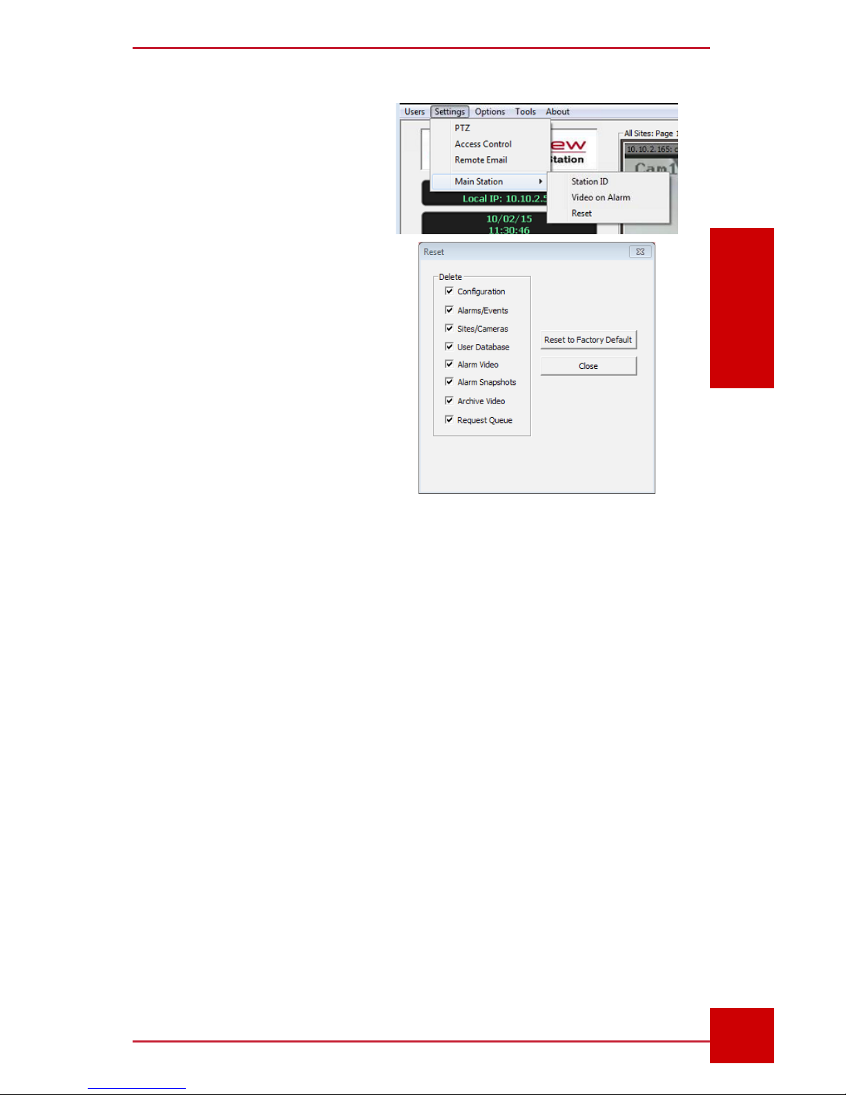
2.1 SC Settings Reset
The initial system set up will
be done by an IntelliView or
IntelliView-authorized installer.
The administrator has the highest
level of user and device control,
including system reset.
The Reset button (Fig. 2) is
located in the Main Station
menu, under the Settings tab.
This function allows the
restoration of all or selected
settings.
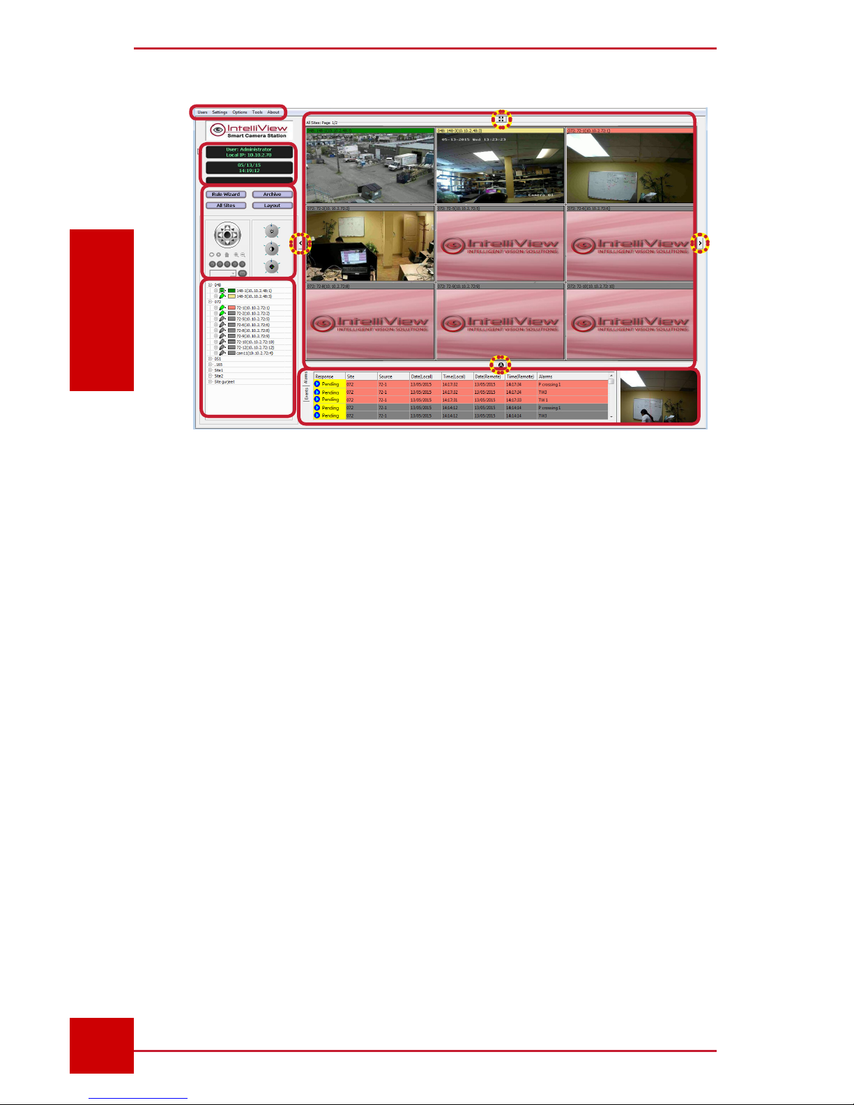
2.2 SC Interface
The SC interface contains several components (Fig. 3).
1. Administration Toolbar (top left of the screen) allows access to:
Users menu - to manage user accounts, sign in and out of the SC.
Settings menu - to congure PTZ cameras, access control devices,
email notications, alarm video recordings, and assign a SC ID.
Options menu - to set new alarms location and storage settings, and
activate functionality of the joystick, verbal alarms, bandwidth saving.
Tools menu for producing the following documents: SmrtSummary,
Count Report and Modbus Report.
2. Status Dialog boxes (three) display the following information:
Figure 2 - System Reset Button
and options
Page 23
SC User Guide — V3.14
www.intelliview.casupport@intelliview.ca
10
SC Interface
Section 2: SC Interface
• Currently logged in user and SC IP address
• Current date and time
• System status and events (E.g. system restart, deleted alarm, etc.)
3. Control Panel provides instant access to several SC tools:
Rule Wizard button: for creating and managing rules.
Archive button: for playback of alarm videos
Layout button: for selecting a layout style for the live video preview
screen
All Sites button: for displaying all live feed screens of active cameras
Pan-Tilt-Zoom (PTZ) Controls: for operating a PTZ camera connected
to the SmrtHVR using the directional buttons and the Preset buttons or
drop-down preset list. The section on the right contains the adjustment
tools for the camera’s aperture, zooming capabilities, and image quality
(brightness, contrast, and saturation). (Refer to Section 4.3 for PTZ
camera controls)
4. Sites and Cameras Panel is where sites and cameras are added and
managed. The camera icon is color coded to indicate its status.
1
2
3
4
5
6
Figure 3 - The SC Interface
Page 24

SC User Guide — V3.14
www.intelliview.ca
11
support@intelliview.ca
SC Interface
Section 2: SC Interface
Green: online
Gray: ofine due to either having been disconnected or lost power
Crossed Out (X): SmrtHVR disconnected, turned off, or incorrect
camera settings.
5. Video Panel: If using the standard SC, the screen displays live
camera feeds 24/7. If using the SC +, the screen displays the IntelliView
logo constantly, until an alarm is triggered by the analytics. In the SC +,
the streaming time of the alarm video can be set in the camera settings,
accessible by right clicking on the camera icon and selecting Edit.
There are four viewing tools located outside the video panel.
Full Screen icon (center top): for shifting between full screen and
standard screen modes
Left and Right Arrows (active with multiple screens): for navigating
through video screens or screen sets (depending on the layout used).
Manual/Auto Screen Rotation icon (center bottom): to ip video
screens automatically every 20 seconds versus manually (using the left
and right arrows)
Each camera feed window is identied by the information in the camera bar,
which contains the camera’s Site Name, Camera Name, and IP address.
The bar blinks when an alarm goes off.
6. Alarms and Events Panel. This is where the alarms and events lists
are located.
The alarms, along with their video snapshot, are displayed under the
Alarms tab the moment a user-dened rule for each camera is triggered. Up
to 100 alarms can be stored.
Meanwhile, under the Events tab you will nd a list of system actions (E.g.
le deletion) and communication between the SC and the SmrtHVR (E.g.
system registration).
This feature is explained in detail in Section 5.
2.3 Managing Users
The SC allows users to be added, managed and assigned varying
permission levels.
Page 25
SC User Guide — V3.14
www.intelliview.casupport@intelliview.ca
12
SC Interface
Section 2: SC Interface
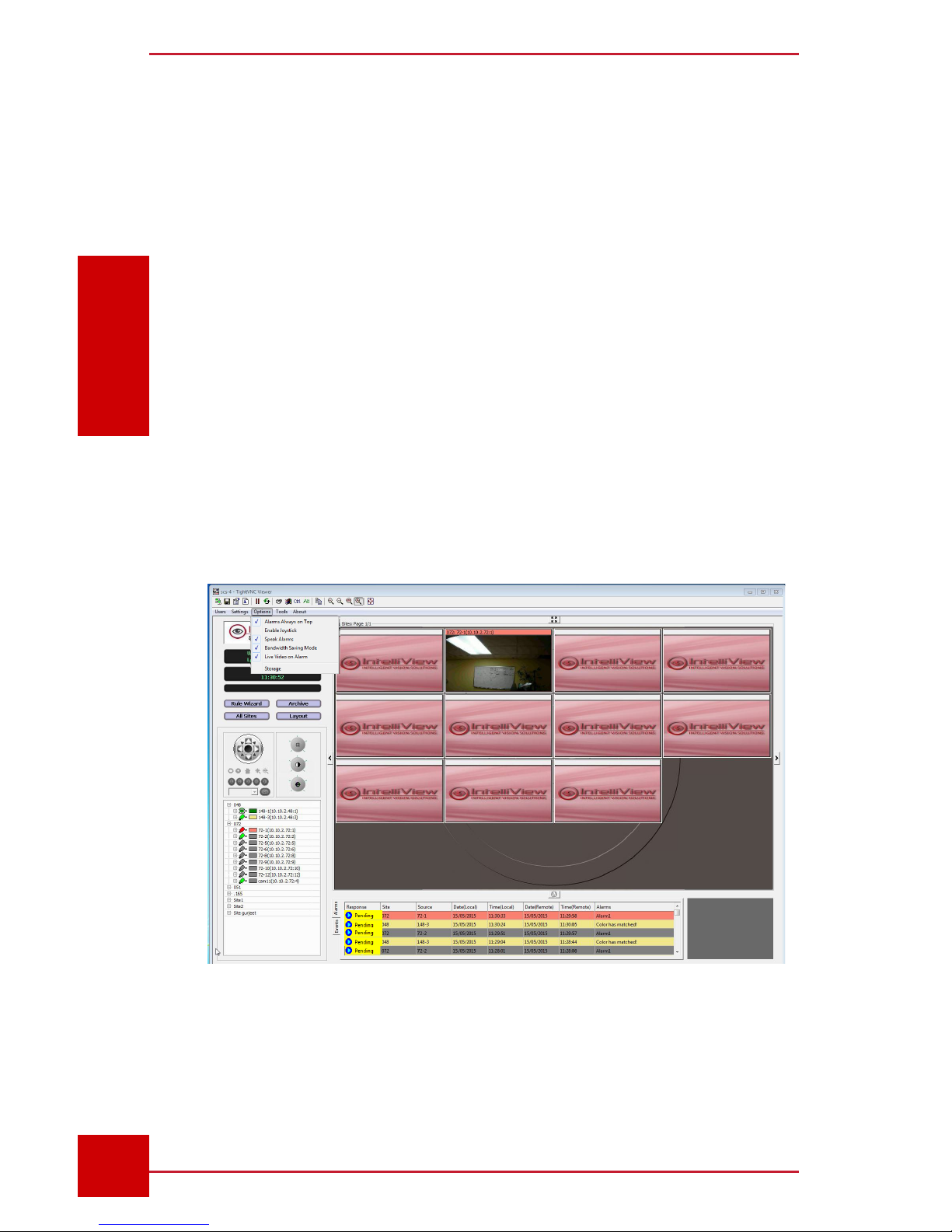
2.5 Black Screen (Bandwidth Saving) Mode
Video streaming incurs data usage charges. There may be situations where
bandwidth is restricted or data fees need to be kept low. In such scenarios,
the SC can operate in Black Screen (bandwidth saving) Mode. This feature
is located under the Options tab of the toolbar (Fig. 4).
In this mode, live feeds will not stream from the SmrtHVR into the SC.
instead, the IntelliView logo will be on constant display. In this mode, there
is the option to show or hide the live footage of a progressing alarm, using
the Live Video On Alarm tool, which is enabled by default and can be
disabled at the user`s discretion at any time.
In Figure 4, both the Black Screen mode and the Live Video on Alarm
feature are enabled. The second video screen is shown streaming the
alarm footage as a result.
Either way, alarm video and non-alarm video recordings are still viewable in
the Archive Player, provided that the les exist in the associated SmrtHVR.
Figure 4 - Low Bandwidth Mode - with alarm showing in Channel 2
Page 26
SC User Guide — V3.14
www.intelliview.ca
13
support@intelliview.ca
SC Interface
Section 2: SC Interface
2.3.1 Startup
At installation, an Administrator user is created. The “Admin” user can
neither be deleted nor have its privileges altered. Its login details can be
changed once during a session. Additional operators can be added, and
their user settings congured. (See Section 2.3.2 for User Settings).
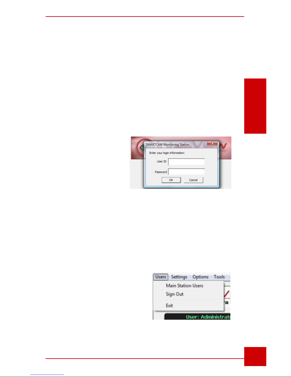
To use the SC, you must be logged in.
1. Click the SC Icon (eye logo) located on the desktop, or anywhere on
the screen, or press any key to open the login box (Fig. 5).
2. Enter the default User ID
(admin) and Password
(admin).
3. Click the OK button. The
SC interface will load, as
shown in Figure 2.
Before proceeding, we
recommend resetting the
primary User ID and Password
for security purposes. The instructions for this, and adding additional users,
are detailed in the next section.
2.3.2 Users Settings
An administrator has complete system access and can modify his own user
details. They can also add other users (E.g. operators) and grant/limit their
User Security Privileges and access to specic features.
The left pane contains the user list
(name and Login ID) and the right pane
displays the privilege list that shows
which are enabled and not.
To Add a New User:
1. In the Users Security Privileges
dialog box, click the Add User button.
Figure 5 - Login box
Figure 6 - Users settings
Page 27
SC User Guide — V3.14
www.intelliview.casupport@intelliview.ca
14
SC Interface
Section 2: SC Interface
The Add Monitoring Station User dialog box (Fig. 8) will appear.
2. Enter user login details in the following elds: Name, User ID,
Password, and Retype Password.
The account can be deactivated by checking the Account is Disabled box.
3. Under the Permissions submenu, check the privileges to be granted
While the administrator, by default, has full access to the system, a user
will be able to view, operate, or modify only the settings and tools he has
permission to, as specied here. For example, a user whose “Rule Wizard”
is disabled will be denied access to the Alarm Rule Setup dialog. This will
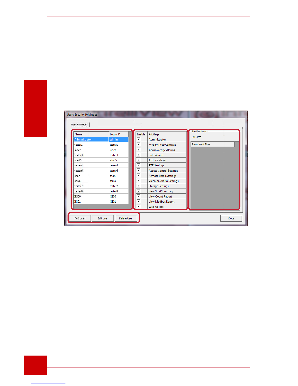
Click on Main Station Users (Fig. 6) under the Users menu on the toolbar
(Fig. 6). This opens the Users Security Privileges dialog box (Fig. 7),
where administrators can perform the following functions:
• Create, modify, and delete user accounts
• Manage user permissions for system access, settings and features
• Manage site access of that user
Figure 7 - User Security Privileges dialog box
Page 28

SC User Guide — V3.14
www.intelliview.ca
15
support@intelliview.ca
SC Interface
Section 2: SC Interface
be apparent to the user as the
Rule Wizard button will not be
active.
4. Select user Site Access:
All or Limited. If Limited
is selected, click the
Modify button. This will
load the Site Access
dialog box (Fig. 9).
5. Select one or more sites
(click Ctrl key + click site)
from one panel and click
the appropriate arrow
button to move it to the
other panel.
6. Click the OK button to apply
changes and return to the Add
Monitoring Station User dialog
box.
The newly created users/
operator can now access
the SC video management
software using their new User
ID and Password.
Users who are not given the
Modify Users privilege will still
have access to the Main Station User settings to change their personal
password; however, he/she will not have the option to add, edit, or delete
other user proles.
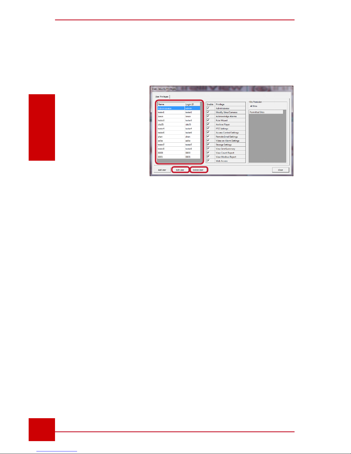
To Edit or Delete a User:
An administrator can modify user account details and remove users in the
User Security Privileges dialog box (Fig. 10)
1. Select the user account from the list.
2. Click the Edit button to launch the user settings box.
Figure 8 - Add Monitoring
Station User dialog box
Figure 9 - Selecting user site access
Page 29
SC User Guide — V3.14
www.intelliview.casupport@intelliview.ca
16
SC Interface
Section 2: SC Interface
3. Modify user information and/or privileges.
4. Click the OK button to apply changes and exit the dialog box.
A user can be permanently deleted using the Delete button. A conrmation
message will appear.
Clicking Yes will apply
changes.
2.4 Live Camera Feed Selection and View
Options
Live camera feeds
(or live alarm feeds in
the “Black Screen (data
saving) Mode” are displayed in the video panel of the SC’s main user
interface. Live feeds can be viewed multiple ways: All Sites, by site, single/
full screen, multiple screens, automatic rotation, and so on. To display only
the cameras of one site in the video panel pages, double-click on that site.
To display all sites, click the All Sites button (Fig. 11).
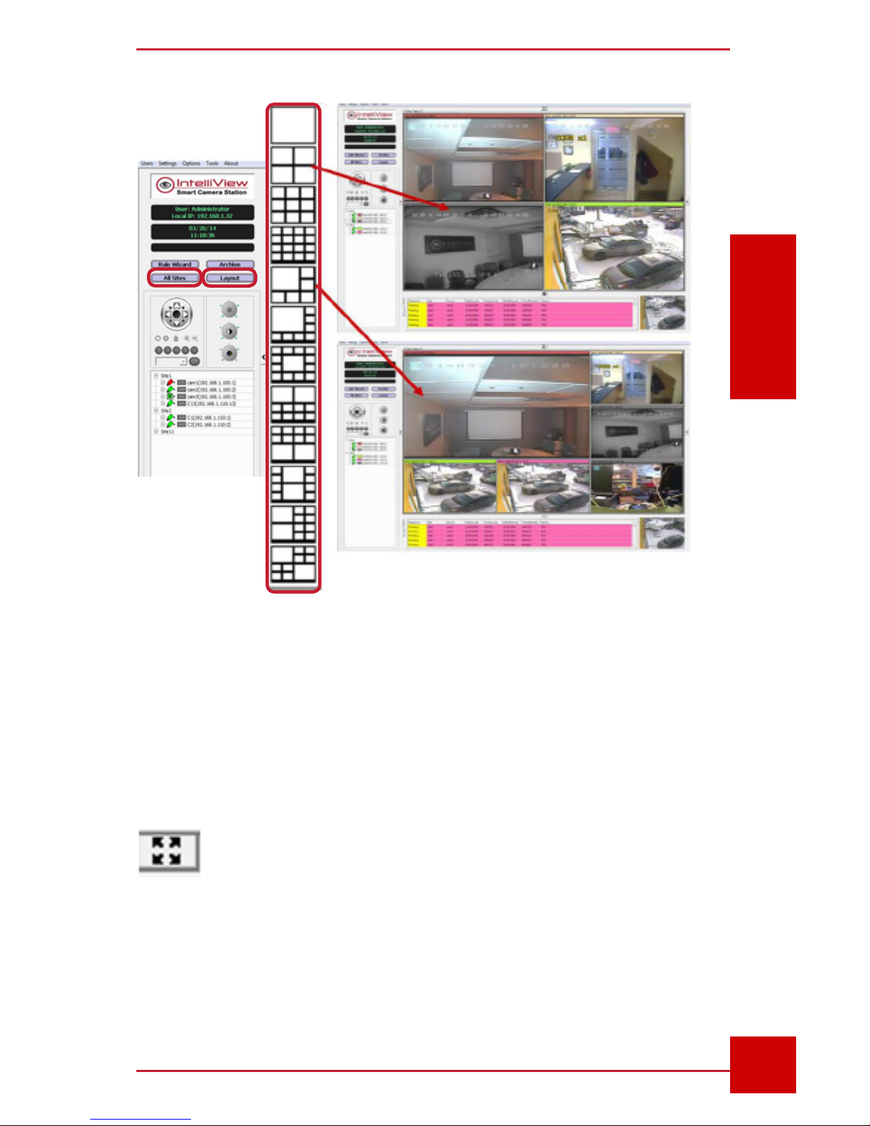
2.4.1 Changing Live Camera Panel Layout
The video panel can display camera feeds in several layouts, including
single view and various grid styles. When the Layout button (Fig. 11) is
clicked, a drop-down menu of layouts will appear. The selection here will be
applied to the video panel (Fig. 12).
Up to 16 screens can be viewed at a time. If the number of cameras outnumber the number of screens available for a chosen layout, use the left
and right arrow icons to navigate through the camera screens.
2.4.2 Changing Camera Viewing Mode Between Single
(full screen) and Multiple View
A live camera feed screen can be viewed in full screen by double clicking it
regardless of the layout applied. Double clicking the expanded/single view
camera screen again will restore the original or pervious layout.
The Full Screen icon (illustrated as four outward arrows) above the video
Figure 10 - Editing user info or deleting users
Page 30
SC User Guide — V3.14
www.intelliview.ca
17
support@intelliview.ca
SC Interface
Section 2: SC Interface
Figure 11 -
Layout tab in
Control Panel
Figure 12 - Switching between different layouts
panel can be clicked to expand the size of the selected camera video
screen to completely cover the SC’s main screen. The Full Screen icon
can also be applied to the video panel in any layout mode. To revert to the
previous viewing mode, click the icon again.
2.4.3 Viewing Live Camera on Auto Rotation
When there are more camera feed screens than the number
of screens shown by a selected layout, the left and right arrow
icons allow the operator to navigate through screens manually.
However, in certain circumstances, it is necessary to monitor several
cameras constantly. The SC allows the user to view screens on automatic
Page 31

SC User Guide — V3.14
www.intelliview.casupport@intelliview.ca
18
SC Interface
Section 2: SC Interface
rotation, ipping the screen every 20 seconds.
At the bottom center of the video screen is an icon with either the
letter “A” for auto rotation or the letter “M” for manual, depending
on the current viewing mode. If the screen is on manual mode,
then the “A” icon will be shown. Similarly, if the auto mode is
used, then the “M” icon will be shown.
2.4.4 Manually Switching Video Screens in the
Video Panel
The position of live camera feed screens of a site (not across sites)can be
rearranged in two ways:
1. Click on a screen, hold the mouse button, drag to its new location, and
then release the mouse button.
2. Open the right-click menu (Fig. 13) and select a screen. It is not
necessary for both screens to be visible on the current page of the
panel to make the switch.
2.4.5 Video Feed Quality Adjustments
The brightness, contrast and color
saturation of video feeds can be
adjusted to optimize viewing.
These video adjustment buttons
(Fig. 14) are located on the right of the
PTZ controls on the main dialog box
of the SC main interface
Figure 13 - Switching video screen panels
Page 32

SC User Guide — V3.14
www.intelliview.ca
19
support@intelliview.ca
SC Interface
Section 2: SC Interface
Brightness: controls image lightness/darkness
Contrast: controls image vividness
Saturation: controls image color intensity
2.4.6 Color Coded Video Screens
Live video feed panels can be distinguished from
each other by the color of their info bar or on-screen
display (OSD). This is located at the top of each
video screen. As shown in Figure 15, the background
of the OSDs are in color neon green, blue, red, and
gray. The colors match both the box next to the
associated cameras in the Site and Camera panel
and the alarms in the Alarms and Events panel.
The color can be selected in the camera properties window when adding or
editing a camera. This is explained in more detail in Section 4.
Figure 14 - VIdeo
adjustment controls
Figure 15 - Color-coded vIdeo screen info bar
Page 33

SC User Guide — V3.14
www.intelliview.casupport@intelliview.ca
20
SC Interface
Section 2: SC Interface
Page 34

SC User Guide — V3.14
www.intelliview.ca
21
support@intelliview.ca
Analytics Rules
Section 3: Analytics & Alarm Rules
Analytics &
Alarm Rules
Section 3
Page 35

SC User Guide — V3.14
www.intelliview.casupport@intelliview.ca
22
Analytics Rules
Section 3: Analytics & Alarm Rules
3: Analytics & Alarm Rules
IntelliView’s analytics software is an industry leading innovation. Contained
in intelliView’s video processing and rerecording devices. This powerful
technology is the intelligence which, like an operator, performs automated
analysis and response upon object detection.
The work of a security operator often includes repetitive tasks. For example,
an operator might be expected to:
• Monitor the number of people coming into or out of a doorway
• Make sure that no unauthorized personnel crosses into the
employees only zone in a building
• Be on alert for items left behind such as luggage or shopping bags
• Keep an eye on valuable items that can be stolen
Much effort and time are required to keep track of events 24/7. IntelliView’s
analytics offer a new and easy way to manage and automate tasks to free
up an operator’s time and make security systems more efcient.
All the tasks mentioned above (and more) can be performed automatically
and in real time by the SmrtHVR. This means there is no delay between an
event occurring and being detected for the system to raise an alarm.
3.5.1 Types of Standard Analytics Rules
Rules are simple sets of specications that say what to look for, where to
look for it, and what to do if it happens. Analytics are dependant upon user
dened rules, which the user can access directly from the SC.
The SmrtHVR model and the licensing dictate the number of rules per
device and camera. The rule capacity of the Rackmount model is eight per
camera but 32 in total, while the IVV is four per camera but eight in total.
Rules in any camera within a SmrtHVR can be combined to create a more
sophisticated and powerful rule.
Note: A camera connected to a SmrtHVR rst needs to be added to the SC
before any analytic or alarm rule can be set up or modied in this device.
(Refer to Section 3.2 on creating/modifying analytic rules).
Page 36

SC User Guide — V3.14
www.intelliview.ca
23
support@intelliview.ca
Analytics Rules
Section 3: Analytics & Alarm Rules
1. Motion Inside Region
An alarm will be raised when movement is detected
within the specied region. Any motion outside this
region will be ignored.
2. Perimeter Crossing
An alarm will be raised when an object passes
through a virtual region or boundary (i.e. when
motion originates from outside the boundary,
crossing into the boundary).
3. Object Taken Away
If an object in the scene disappears, the system will
raise an alarm. This can be used in theft prevention
as well as safety monitoring.
4. Object Left Behind
The software can detect if a new object has been
placed in the frame. This is something that was
not there before, such as an abandoned briefcase
or forgotten handbag. This can be used for public
safety monitoring.
5. Trip Wire (One Direction)
The software can detect motion that crosses a line
in one direction. Movement crossing the line from
the opposite direction will not trigger an alarm. This
can be used when it is important to monitor people
coming in but not going out.
The following are analytic rules that can be used for security and general
surveillance applications.
Page 37

SC User Guide — V3.14
www.intelliview.casupport@intelliview.ca
24
Analytics Rules
Section 3: Analytics & Alarm Rules
3.5.2 Types of Specialized Analytic Rules
IntelliView also offers a number of specialized analytics rules, which may be
customize, for specic industrial applications. These include:
1. Liquid Leak Detection: This analytic analyzes video feed from
a camera to monitor for liquid leaks. The leak is detected with a
thermal camera (outdoor) through temperature difference between
the object and the surroundings, and with a color camera (indoor)
through color matching. Sprays, drips, and pooling the size of a
sheet of paper at 50m can be detected within user dened areas.
6. Trip Wire (Both Directions)
The software can detect motion that crosses a
single line, in either direction. This is the same
as Trip Wire (One Direction), but works for both
directions.
7. Loitering
An alarm will be raised if a person is detected to
be loitering. This type of analytics looks for typical
human behavior based on specic rule parameters,
such as time spent at a region of interest (ROI).
8. Digital Input
The IVV SmrtHVR has 4 built in Digital I/O (DIO) pins which can be
programmed as inputs or outputs of 5v each. The Rackmount model can be
connected with an external non-programmable DIO port (ADU200). These
are typically used for external user input (E.g. door contact) or output (E.g.
light or siren). The use of the digital I/O’s are congured as rules added
to a camera, and are alarm triggers when dened as inputs. A digital I/O
input rule, in conjunction with a switch, could be used to temporarily disable
analytics to prevent false alarms when personnel are on site.
9. SmrtLOCK Access Control
The software allows the application of an access control policy as dened
in the access control reader settings. This is typically used in security
applications to grant access to specic people at specic times. The
SmrtLOCK analytics enables alerts to be raised for user-dened events.
Page 38

SC User Guide — V3.14
www.intelliview.ca
25
support@intelliview.ca
Analytics Rules
Section 3: Analytics & Alarm Rules
2. Color Match Detection: Used to detect uid leaks in indoor pump
stations that have consistent lighting conditions. The analytics
monitors regions, such as oor and drain areas, for colors specic to
targeted products. Color cameras provide cost a more cost effective
solution for indoor applications.
3. Temperature in Region: Detects objects with a temperature rating
above or below a specied value within a dened analytic region. It
eliminates false alarms caused by non-targeted objects that do not
share the temperature attributes of the object monitored. The value
in Wait Time is the time in seconds that a valid object must be in view
to trigger an alarm. With the Isotherm enabled, colors representing
heat levels will appear.
4. Bird Detection - This analytics combines radar, thermal, and color
cameras to provide a robust solution to prevent birds from landing
in settling ponds. The system can operate in rain, fog, snow and all
other weather conditions that can force birds to land, and in which
other solutions may be unable to function. It is automated and can
be slaved to air cannons or other devices already in place.
5. EFOY Voltage Monitor: This analytic rule is used to monitor the
voltage of the EFOY output. While this rule is active, the SmrtHVR
generates an alarm message when the voltage drops below the
specied value. When the voltage is below the specied limit, it will
continue to generate an alarm every so hours as specied in the
alarm frequency eld.
6. EFOY Error Monitor: Monitors the EFOY fuel cell for any type of
error message that it generates, including low fuel notication. While
this rule is active, the SmrtHVR monitors any type of error message
that the EFOY cell generates and sends the messages to the
SmrtHVR. As long as the EFOY cell continues to generate errors,
the SmrtHVR will continue to post error messages every so hours as
specied in the alarm frequency eld.
7. Fire Detection: This Analytics is able to detect re within a region of
interest (ROI). Rectangle is the analytic region shape supported. The
parameters requiring specication are: Target Color, Acceptance %
(minimum object size relative to the size of the analytic region), and
Likeness % (extent of color similarity needed).
Page 39

SC User Guide — V3.14
www.intelliview.casupport@intelliview.ca
26
Analytics Rules
Section 3: Analytics & Alarm Rules
8. Missed Flame Detection: This analytics is able to detect the
absence of a ame within the region of interest. Like re detection
analytics, the region shape supported is rectangle. The ame to be
monitored has to be within the drawn ROI. The Target Color, the
Likeness % and the Acceptance % have to be specied.
9. Face Detection: This analytics is able to differentiate a human face
from an animal’s face and identify facial hair on a human face for
safety and security applications.
10. Modbus - The Modbus interface allows the SmrtHVR to operate
as either a Master or Slave device in a Serial or TCP/IP Modbus
architecture. Analytic alarms, heartbeat monitors, and PTZ control
are some of the functions built into the Modbus register map. For
a full list of Modbus functionality, contact IntelliView or refer to the
SmrtHVR Manual.
11. Speed Limit Violation: Speed thresholds are dened for a radar
device where if the dened speed is exceeded, an alarm will be
triggered.
12. People/Vehicle Count: The number of objects crossing in a dened
direction is counted and recorded. This is a counting analytics so
no alarm action is performed and the settings for alarm action are
ignored.
3.1 Types of Regions
Analytics are in effect in a dened region. The region is a virtual section in
the camera scene (it could be large enough to cover the whole screen)
where the analytics are active.
The IntelliView software supports three types of
regions (or boundaries): rectangle (Fig. 16), straight
line (applicable only to trip wire), and polygon.
A polygon is an arbitrary shape (Fig. 17) that can have
any number of sides and vertices. Any polygon shape ,
including rounded gures as shown in Figure 18, can be
drawn to accommodate any scenario (see following sub
sections on drawing instructions).
Figure 16 - A
rectangular
area of effect.
Page 40

SC User Guide — V3.14
www.intelliview.ca
27
support@intelliview.ca
Analytics Rules
Section 3: Analytics & Alarm Rules
Rectangles may sufce for simple rules but are inadequate for \more
complex situations, such as monitoring a doorway at an angle, or a site with
an unorthodox layout (e.g. remote site with rough terrain).
Facilities of this type require the
denition of a large area of effect that
needs to have a region of exclusion
within it (i.e. a region where the rule
would not apply).
Applying a polygon is simple and can
effectively dene sophisticated areas for
application of analytic rules. It is designed
to eliminate the use of multiple boxes for
one or more rules intended for a single
monitored scene.
3.1.1 Drawing a Box Analytic Region
Note: Drawing is done in the Alarm
Rule Setup window and after making
a shape selection.
To draw a box shaped region, place
the mouse curser on the camera
window then click and release to place
an anchor point.
This will be the start of the rectangle
(one of its corners) which is locked
in place. As the mouse moves, a
rectangle is drawn. Left click to
complete the process.
Figure 17 - Examples of polygon areas.
Figure 18 - Polygon drawn
as a rounded shape
Figure 19 - Drawing a square
or rectangle shape
1
2
Page 41

SC User Guide — V3.14
www.intelliview.casupport@intelliview.ca
28
Analytics Rules
Section 3: Analytics & Alarm Rules
3.1.2 Drawing a Polygon Analytic Region
When drawing a polygon (Fig. 20) think of connected lines that form a
unique shape. To draw a polygon, begin by using the same methodology as
with drawing a box (Section 3.1.1).
Once a starting point has been set, slide the mouse up to the point where
the line’s endpoint needs to be and click. Then slide again and click.
Repeat the slide-click-slide action until the desired shape and coverage are
established. Double click to link the starting point with the last point.
Figure 20 - Drawing a polygon with
2
4
3
1
5
7 6
Page 42

SC User Guide — V3.14
www.intelliview.ca
29
support@intelliview.ca
Analytics Rules
Section 3: Analytics & Alarm Rules
3.1.3 Drawing a One-Way Trip Wire
A single directional trip wire (Fig. 21) has an arrow facing one way. This is
used for detection of objects moving in one direction, for instance, people
coming in through the door and not out.
The arrow can be pointed at any direction. To draw a trip wire, left click
on a starting point, and without releasing drag the mouse pointer to the
intended length, and move clockwise or counterclockwise until the desired
direction of the arrow is achieved, and then release.
3.1.4 Drawing a Two-Way Trip Wire
A multidirectional trip wire looks like a plain line with no arrows. It is drawn
using the same methodology described in drawing a one-way trip wire
(Section 3.1.3).
3.1.5 Changing the Shape of an Analytic Rule
To apply a new shape to an analytic region, select the associated rule,
select the new shape in the Rule Shape pane, and draw as described in
the above subsections. Any change or update to a rule is applied only after
clicking the Update Rule button and the Apply Changes to Camera button.
Figure 21 - One-way trip wire
Page 43

SC User Guide — V3.14
www.intelliview.casupport@intelliview.ca
30
Analytics Rules
Section 3: Analytics & Alarm Rules
3.2 Analytic/Alarm Rule Management
The rule management feature of the SmrtHVR
can be accessed and manipulated from the SC.
This enables the SC user to view, add new and
modify existing alarm rules for each camera
connected to linked SmrtHVRs.
All changes occur in the SmrtHVR and the SC
simply acts as a remote viewer and controller.
Rules are created and managed in the Alarm
Rule Setup dialog box, which is accessible by
clicking the Rule Wizard button (Fig. 22).
The Alarm Rule Setup dialog box (Fig. 23)
Figure 22 - Rule
Wizard button
Figure 23 - The Alarm Rule Setup dialog box.
1
4
5
3
2
Page 44

SC User Guide — V3.14
www.intelliview.ca
31
support@intelliview.ca
Analytics Rules
Section 3: Analytics & Alarm Rules
consists of several elements:
1. Camera List: From the drop down menu you can select the camera
for which rules are to be created or edited.
2. Preview Screen: The preview screen displays an image of the live
feed from the selected camera.
3. Rule List (below the preview screen): This section contains all
the rules that exist or have been set for the selected camera. The
entries will vary by camera. From here, it is possible to add, update,
delete or combine (coupling) rules. When a rule is selected the color
of its shape/region changes in the camera preview screen.
4. Rule Properties: This is where rules are set and congured: name,
type, preferred action when triggered, among other settings.
5. Object Detection Settings: These settings determine the criteria for
detecting objects in the video. In other words, these settings tell the
SmrtHVR how to know if something is an object.
3.2.1 Adding and Updating Rules
Rules are added on a per-camera basis. Each camera can accommodate
four to eight rules based on the capacity of the device model.
Before a rule can be added or modied, a camera needs to be selected
from the drop-down list. The preview screen will change to show the live
feed from the chosen camera and the Rule List (Fig. 24) will display the
rules that exist for that camera.
Ensure that the correct camera is selected.
Figure 24 - Rule List panel - for adding, editing, and deleting rules
D
A
B
C
F
E
G
Page 45

SC User Guide — V3.14
www.intelliview.casupport@intelliview.ca
32
Analytics Rules
Section 3: Analytics & Alarm Rules
Here are its parts and functions:
A: The “On” checkbox determines whether a rule is active or not
When a new rule is created, it is enabled by default. If this box
is unchecked, the rule will not generate alarms.
B: The Rule Description eld is where the rule’s name is entered.
This is reected in the Rule List panel.
C: The Rule Type eld shows what kind of rule it is. Analytic rules
are shown in red on the preview screen. When selected, the
rule’s color will turn blue to differentiate it from other rules.
D: The Add Rule button is used for adding a rule. The rule rst
needs to be selected from the Rule Type list, drawn on the
screen, and congured from the rule properties panel.
E: The Update Rule button is used to modify an existing rule.
The rst needs to be selected in the Rule List panel, and then
modied in the Rule Properties panel.
F: The Delete Rule button is used to permanently delete a rule
that is selected in the Rule List panel.
G: The Coupling button is used to combine rules from any
camera in the same recorder to create a sophisticated rule set.
Important: Once modications are completed, click the Apply Changes to
Camera button to save and apply the new conguration.
Note: Some alarm rules require a 30 second calibration period during
which time the rule will be inactive. The image area must be stable during
the calibration period for calibration to take effect. Calibration start time and
end time are recorded in the Events log.
3.2.2 The Rule Properties Panel
Alarm rules are created and congured in the Rule Properties panel (Fig.
25), which consists of the following elements:
1. Rule Description: The name of the rule is entered here. It can be a
name that makes the rule easy to identify, for example: North Entrance
or Parking Lot Exit.
Note: First select a rule from the Rule Type list (item 3) before entering
a name so that the new name will not change to its default generic name
(E.g. Rule 1, 2, 3, etc.).
Page 46

SC User Guide — V3.14
www.intelliview.ca
33
support@intelliview.ca
Analytics Rules
Section 3: Analytics & Alarm Rules
2. Rule Type: The selection here will determine what the rule will do,
or what kind of movement will trigger this rule. Refer to Section 3,
Analytics & Alarm Rules, for a description or function of each rule.
3. Rule specic options vary according to what applies to a selected
rule type. In the example in Figure 25, Motion Inside Region requires
a region of interest (ROI) to be dened, therefore, the Rule Shape
options are shown. Rule shapes include a line (applicable only to trip
wire rules), a rectangle and a polygon. Refer to Types of Regions
(Section 3.1) for application of shapes, and drawing instructions.
4. Setup Schedule button: This is used to specify when a rule is active:
Always Active or on certain days/times. Refer to Rule Scheduling
(Section 3.3) for details.
The Rule Action panel contains additional settings that inform the system’s
behavior, such as:
5. Count: This feature serves as a counter for the number of times this
rule is triggered. Section 5.5 explains how to create Count reports.
Figure 25 - Rule
Properties panel
1
3
4
5
6
7
8
9
11
10
2
12
13
14
Page 47

SC User Guide — V3.14
www.intelliview.casupport@intelliview.ca
34
Analytics Rules
Section 3: Analytics & Alarm Rules
6. Generate Alarm Message: This option enables the rule to send out a
message when an alarm is triggered. The message displayed will be
identical to the one entered in the text box.
7. Modbus Reporting (not related to the Modbus Report under the Tools
tab in the toolbar): The system runs as a slave server that allows alarms
to be recorded in the PLC device. The Modbus Reporting option should
be checked to enable this feature.
8. Send Notication Email to: This option is used to transmit an
alarm email notication to the address specied in the text box. A
video snapshot of the alarm (and from another camera if this option
is enabled) will be included. To send to multiple recipients, use a
semicolon (;) without any space to separate addresses. Ensure that the
SmrtHVR is setup for email transmission (see Section 3.9 for more).
9. Attach Snapshots from Another Camera: This option is used to
capture alarm images from another camera pointing at a scene that is
the same or related to the selected camera (E.g. entrance and lobby).
10. Trigger Relay Number: This enables the system to activate an external
digital IO device (connected through a serial or USB connection). The
port number of the external device needs to be specied in the text box.
The value should match the output specied in the DIO Settings. (Refer
to Section 3.8 for further information on DIO)
11. Trigger PTZ Camera: This option enables the alarm to point a pan-tiltzoom (PTZ) camera connected to the system to a related PTZ preset.
When enabled, specify a PTZ camera (if more than one is connected to
the system), and a preset.
12. Lock and Track: This enables the PTZ camera to lock on and track the
movement of the object that triggered the alarm. This option only applies
to PTZ cameras.
13. Minimum Delay Between Consecutive Alarms: This is used to control
the frequency of alarms being triggered.
This option is useful when numerous alarms are generated for the same
event. If this option is unchecked, there is no time-out period between
the last alarm and the next. The time-out period determines how long
before that a rule can be triggered again. This means after the rule has
been triggered, it will be inactive until the specied time passes.
14. Object Size: This is used to dene the dimension of the targeted object
(E.g. a small dog or a person) for enhanced accuracy in detection. Refer
to Section 3.5 for details.
Page 48

SC User Guide — V3.14
www.intelliview.ca
35
support@intelliview.ca
Analytics Rules
Section 3: Analytics & Alarm Rules
3.2.3 Rule-Specic Options
Some rules have sub options, such as shape, direction, time and speed.
These are displayed on the right of the Rule Type panel (Fig. 26) when a
rule is selected.
Types of rule-specic options:
1. Rule Shape - Options could be a line (applicable to trip wires only), a
rectangle/box, and a polygon, depending on the rule type selected.
The mouse is used to draw the appropriate area of effect: Drawing
instructions are detailed in Section 3.1
2. Rule Shape with Time - This
option will appear when a rule,
such as Loitering (Fig. 26)
or Liquid Leak Detection, is
selected. The time specied tells
the rule how long an object is
required to stay in view before it
triggers.
3. Digital Input Number (DI#) -
The SmrtHVR/NVR may come
with built-in digital input and
output (DIO) interface or
an external DIO with a USB
connector (sold separately).
This relay is used to trigger
an alarm based on user input
(door contact or touch button)
occurring in view of a camera
connected to the SmrtHVR/NVR.
This rule requires a digital
input (Fig. 27) to be selected
from a drop-down list. Refer to
Section 3.8.
Figure 26 - Loitering: Rule
Shape with time.
Figure 27 - Selecting the source of
input from the drop-down menu.
Page 49

SC User Guide — V3.14
www.intelliview.casupport@intelliview.ca
36
Analytics Rules
Section 3: Analytics & Alarm Rules
4. Reader Number - When the
SmrtLOCK Access Control
rule is chosen, you will be able
to select a reader number
from the drop-down menu.
The number corresponds to
a binary setting in the access
control board. SmrtLOCK
controller enables cardlock
access to a number of doors
for added security. (Refer
to Section 6.2 for further
information.)
5. Alarm Frequency (with or w/o Voltage) - EFOY is a green energy
generator that may be used with an IntelliView solution. When the
EFOY Error Monitor rule is selected, it is possible to specify the
trigger time between the rst and the next alarm. This is similar to the
Minimum Delay Between Consecutive Alarms feature except that the
interval is in hours instead of seconds.
The EFOY Voltage Monitor requires a voltage number to be specied.
This tells the system to trigger an alarm if the voltage of the EFOY falls
below this number. For example, in Figure 29, the voltage number is
set to 10. If the EFOY generator’s voltage goes down to 9, then it will
trigger an alarm. Should the voltage remain or again drop below 10
after the frequency hours specied, another alarm notication will go off
again.
Figure 28 - Reader# drop-down
menu for SmrtLOCK Access Control.
Figure 29 - Alarm frequency option
with minimum voltage setting.
Page 50

SC User Guide — V3.14
www.intelliview.ca
37
support@intelliview.ca
Analytics Rules
Section 3: Analytics & Alarm Rules
6. Port Number with KMH - This option
becomes available when the Bird Detection
or the Speed Camera rule is selected. The
Port number corresponds to the device
connected to the SmrtHVR, such as a n
IntelliView radar gun. Your entry in the
KMH eld will indicate the maximum speed
the camera will remain inactive. Above the
specied value, the camera will be triggered
to take a photo.
7. Modbus - This rule applies to the
SmrtHVR operating as a Master or Client
Device in a Serial or TCP/IP MODBUS
environment. Before this setting can be
congured, a Modbus device must rst be
added. (See Section 9 of SmrtHVR manual
for setup instructions. Note: a technical
person is required to facilitate this setup.)
8. Rule Shape with Color
Match - This applies to the
Color Match Detection (for
liquid leak detection), the Fire
and the Missed Flame rules
and requires the specication
of a color/s that closely
resembles the color of the
targeted object (e.g. oil). The
Congure button loads the
color settings and the Target
Color button is used for color
selection. Only for the Color
Match Detection rule, up to 10
colors can be added via the
Add button in the Color Match
Conguration window (where
the right arrow is pointing in
Figure 32).
Figure 30 - Port
# with KMH
Figure 31 - Conguring Modbus
from the Alarm Rule dialog
Figure 32 - Conguring
the Color Match Rule
Page 51

SC User Guide — V3.14
www.intelliview.casupport@intelliview.ca
38
Analytics Rules
Section 3: Analytics & Alarm Rules
Additional adjustment options are Likeness (minimum percentage or extent
of color similarity) and Acceptance (minimum object size, in percentage in
relation to the region of interest or ROI). These settings improve detection
accuracy and false alarms reduction by adding a layer of alarm condition.
9. Rule Shape with Temperature in Region:
Applied to thermal cameras, this rule enables the system to disqualify
or qualify objects based on their temperature. The specied Wait Time
(5 to 60) is the amount of time in seconds that the temperature needs to
remain above or below the specied temperature value before an alarm is
triggered.
The settings in Figure 33 (Above 30°C) is congured to detect an object
that has a typical minimum temperature of 31°C.
Applications include equipment overheat detection, monitoring processes
involving cooling or heating thresholds such as material drying and cooking.
Figure 33 - Temperature
in Region settings
Page 52

SC User Guide — V3.14
www.intelliview.ca
39
support@intelliview.ca
Analytics Rules
Section 3: Analytics & Alarm Rules
3.3 Rule Scheduling
Rules can be active all the time. However, depending on the situation, this
might not be ideal. For example, running a perimeter crossing detection rule
during daytime in a crowded area may generate numerous false alarms.
The SC allows for rules to be scheduled.
If a rule needs to run all the time (24/7), the Always Active option must be
checked. This is the default setting when a rule is created.
However, if a rule only needs to be active during specic days and times,
un-check the Always Active box. At this point, the Setup Schedule button
will become available. Click to open the dialog box and congure rule
timings.
1. Per rule, the scheduler allows you to appoint up to two schedules per
day. To enable this, check the Two Schedule Settings box.
For example, if a rule needs to be active from 10 a.m. to 3 p.m., not
active between 3 p.m. and 6 p.m., but active again between 6 p.m.
to 11 p.m., check Two Schedule Setting box to enable the second
schedule setting.
However, if a rule needs to be active from 10 a.m. to 3 p.m., but not
active throughout the day, setup the rule’s timings under Schedule
Setting 1. Make sure the Two Schedule Settings box is unchecked to
disable the second settings.
3
2
1
Figure 34 - Rule schedule setup
Page 53

SC User Guide — V3.14
www.intelliview.casupport@intelliview.ca
40
Analytics Rules
Section 3: Analytics & Alarm Rules
2. In the Start and Stop elds, enter the rule’s period of activity or click the
up/down arrows.
3. The rule can be scheduled to run on certain days of the week by
checking the box next to the chosen day/s. To disable the rule on a
specic day, un-check the box next to that day.
The rule can also be applied to weekdays and/or weekends.
The Weekdays button will enable the rule from Monday through Friday
and disable it on Saturday and Sunday.
The Weekends button will enable the rule on Saturday and Sunday,
and disable it Monday through Friday.
Once you are satised with the schedule settings, Click the OK button
to accept the changes, or Cancel to forfeit the changes.
3.4 Auto Illumination Change Compensation
The Illumination Change Compensation feature, when enabled, allows the
system to eliminate sensitivity to lighting to increase the accuracy of the
analytics.
Note: This setting is not recommended for leak detection but advisable for
security surveillance.
Figure 35 - Object detection settings panel.
1
2
3
Page 54

SC User Guide — V3.14
www.intelliview.ca
41
support@intelliview.ca
Analytics Rules
Section 3: Analytics & Alarm Rules
3.5 Object Size Settings for Detection
For detection, it is possible to set a minimum object size (anything smaller
will not trigger an alarm) or a maximum object size (anything larger will
not trigger an alarm).This feature is useful in differentiating objects, say a
briefcase (a small object) from a person (large object) or an animal (small
object) from a car or person (large object).
To Set a Minimum Object Size
1. Check the box to enable this feature.
2. Enter the width and height variables manually in the box.
Alternatively, you can draw the minimum object size on the camera
screen. Only square and rectangles can be drawn. Click the Setup
button to open the screen. Then, set the mouse cursor at the preferred
location of the rst corner and left click to lock in place, then drag and
left click again.
To Set a Maximum Object Size
The same steps apply to the Maximum Object Size tool.
Figure 36 - Object size setup screen.
Page 55

SC User Guide — V3.14
www.intelliview.casupport@intelliview.ca
42
Analytics Rules
Section 3: Analytics & Alarm Rules
3.6 Rule Coupling
Two rules from any camera connected to a SmrtHVR can be combined to
function as a team. However, a rule that is part of a coupling is not able to
trigger an alarm on its own but only when both rules are met. Rules can
be used in more than one coupling, and a maximum of eight couplings are
possible per channel (e.g.: 4-channel HVR = 4 x 8 couplings).
The purpose of rule coupling is to enable the user to create a sophisticated
set of rules to enhance detection accuracy and minimize false positives.
The secondary rule acts as a lter through validation or exclusion. Coupling
of rules between cameras from different SmrtHVR’s is not possible.
The following are combinations of Coupling conditions which control
alarming:
AND - The primary rule is triggered, followed by or at the same time as the
secondary rule being triggered. An alarm will not set off if the secondary
rule is triggered rst. The primary rule, which is the rst rule selected, takes
precedence.
AND NOT - The primary rule is triggered
AND the secondary rule is NOT. This
coupling option is useful when a situation
requires excluding a condition. An example
is monitoring two gates (different cameras)
where people crossing the rst gate must also
cross the second gate within a time frame,
say 20 seconds. In this case, an alarm will be
generated when the object fails to cross the
second gate within 20 seconds.
Note: A coupled rule is not meant to, and will
not, operate independently even when the
other rule is disabled. Disabling a coupled rule
will disable the couplings it is involved in.
There must be least two rules in the
SmrtHVR, in any one or more cameras for the
Coupling button to become active in the Rule
List panel (Fig. 38).
Figure 37 - Rule
Wizard button
Page 56

SC User Guide — V3.14
www.intelliview.ca
43
support@intelliview.ca
Analytics Rules
Section 3: Analytics & Alarm Rules
Figure 38 - Coupling button
To add a rule coupling:
1. Go to the Alarm Rule Setup window by clicking the Rule Wizard
button (Fig. 37) on the SC’s main user interface.
2. Select a camera. Existing rules for this camera will load in the panel
below the camera screen. If rules do not exist, create/add rule/s.
3. Click the Coupling button (Fig. 38).
4. Click the Add button (Fig. 39).
Note: Rules don’t need to be enabled (ON box checked) to be coupled.
However, they need to be enabled for the alarm to set off.
5. Select a rule from the drop-down list:
Figure 39 - Rule Coupling for combining rules
to create a set of sophisticated alarms.
Page 57

SC User Guide — V3.14
www.intelliview.casupport@intelliview.ca
44
Analytics Rules
Section 3: Analytics & Alarm Rules
6. Select a Relation from the drop-down list:
AND - The secondary rule must occur at the same time or after the
primary rule is triggered.
AND NOT - The secondary rule must NOT be triggered together with or
after the rst rule occurring.
7. Select the camera containing the secondary rule from the drop-down
list. This may be the same camera as the one for the primary rule or
another camera connected to the HVR.
8. Select the secondary rule. The drop-down list will only show existing
rules for the selected second camera.
9. Enter an Active Period (between 0 and 255 seconds) during which
the secondary rule needs to be triggered to set off the alarm. If the
secondary rule is triggered after this period, no alarm will take place.
10. Click the OK button to complete the action. The couplings will now be
active.
Repeat the above steps to add additional couplings.
Note: The rst and second couplings are independent of each other (unless
they use the same rules) and have no relationship. One or two alarms
notications may be generated as a result of the “Generate Alarm Message”
option in the Rule Setup window being enabled for either or both rules.
To modify or permanently remove a coupling:
1. Go to the Rule Coupling window (follow steps 1-3 above).
2. Select a coupling.
3. Click the Edit or Delete button.
4. Proceed with the changes, and click the OK button to exit.
Note: Deleting a rule used in a coupling will also delete the coupling but
retain the non-deleted rule, which will then function independently.
Page 58

SC User Guide — V3.14
www.intelliview.ca
45
support@intelliview.ca
Analytics Rules
Section 3: Analytics & Alarm Rules
3.7 Enabling/Disabling Analytics For Each Camera
A rule created/added is enabled by default. It can be disabled and enabled
in the Alarm Rule Setup window. Note, however, that when a rule used in
a coupling (merging of different rules, explained in Section 3.7) is disabled,
the alarm will not get triggered. A warning message will pop up .
1. Select the camera from the drop-down list to show existing rules in the
Rule List panel (Fig. 40).
2. Located on the left of each rule is a check box under the ON column.
Check the box to enable the rule or un-check to disable the rule.
3. Click the Update Rule button to conrm the action.
4. Click the Apply Settings to Camera button.
5. Click the Close button to exit.
Figure 40 - Enabling/disabling rules
from the Rule List panel
Page 59

SC User Guide — V3.14
www.intelliview.casupport@intelliview.ca
46
Analytics Rules
Section 3: Analytics & Alarm Rules
3.8 Externally-Triggered Alarms (Digital IO)
Another way of triggering an alarm is by relaying an external input from
devices such as motion sensors or panic buttons. These devices can be
connected to the SmrtHVR via an integrated or external USB input/output
relay module, depending on the SmrtHVR model, and controlled through
the SC.
An alarm triggered by an external input is not generated by analytics and
is simply a relayed signal from the external device. The SmrtHVR does not
know whether something actually happened, it simply reacts to a command
to trigger an alarm. Hence, an externally triggered alarm is different from
one generated by the system’s analytics, but it can still be managed the
same way.
To set an Externally Triggered Alarm:
1. Create a new rule in the Alarm Rule Setup dialog box.
2. In the Rule Type list box, select Digital Input.
3. Select an external
device ID or DI #.
Since the SmrtHVR
can be connected to
up to eight external
DIO relays (depending
on the model), it is
necessary to assign
each a unique ID to
distinguish between
them. This port cannot
be the same as the
input specied in the
SmrtHVR’s Digital IO
settings.
4. Complete the rule setup procedure as described in previous sections.
An externally-triggered alarm is not different in any way from one generated
by SmrtHVR analytics and can be coupled with other alarms.
Figure 41 - External input
alarm trigger settings.
Page 60

SC User Guide — V3.14
www.intelliview.ca
47
support@intelliview.ca
Analytics Rules
Section 3: Analytics & Alarm Rules
3.9 Remote Email Settings
The SmrtHVR is able to send an email when an alarm is triggered. This
feature is critical for remote monitoring, notifying incident watchers/
responders, and simplifying management of the surveillance solution.
SmrtHVR email settings can be directly managed using the SC. An internet
connection is necessary for email transmission. In the event of internet
disruption, emails will be saved automatically and immediately transmitted
once connectivity resumes.
The settings for Remote Email are accessible from the Settings menu
(Fig. 42).
1. Select a SmrtHVR from the list. Each SmrtHVR is congured
independently.
2. Check the
Enable Email
Sending
box. If this is
unchecked,
emails will not
be sent.
3. Enter the
Sender
Name. This
is the name
(e.g. John
Smith) of the
person from
whom the
email will be
sent.
Figure 42 - Remote Email Settings
Page 61

SC User Guide — V3.14
www.intelliview.casupport@intelliview.ca
48
Analytics Rules
Section 3: Analytics & Alarm Rules
4. Enter the Sender Email. This is the email address of the sender from
which the email will be sent. An example of an email address is john.
smith@intelliview.ca.
Note: Ensure that the email address is correct; otherwise, notications will
not be sent.
5. Enter the SMTP Server address. this is the mail server that the
SmrtHVR will try to connect to in order to send the email. If not known,
ask your network technician or support.
6. Enter the SMTP Port Number. This is the TCP/IP port that the
SmrtHVR will use to connect to the SMTP server at the address
specied above. If not known, use the default value 25.
7. If the SMTP server requires authentication, such as a username and a
password (it is very likely that it does), then check the Server Requires
Authentication box.
8. Enter the Username and Password.
9. In the “To” pane, enter the recipient address(es) in the Default
Recipient Email eld. Up to ve email addresses can be entered.
Separate email addresses with a semicolon (;). For example, john.
smith@intelliview.ca; jsmith@intelliview.ca.
10. Click the Send Settings to the DVR button to apply the changes to the
remote device.
11. Click Test Settings button to verify if the SmrtHVR is able to send an
email. A test email will be sent to the Default Recipient Email address
specied.
If the test email is received, the SmrtHVR is ready to send emails. If an
email is NOT received, this means that the connection test has failed.
Do the following:
• Check that the Sender Email address entered is correct.
• Check with your technical support if the SMTP Address and the
SMTP Port are correct.
• If the Server Requires Authentication option was not enabled,
enable it and try again (username and password required).
• If multiple addresses were entered, try with a single email address.
Page 62

SC User Guide — V3.14
www.intelliview.ca
49
support@intelliview.ca
Analytics Rules
Section 3: Analytics & Alarm Rules
Page 63

SC User Guide — V3.14
www.intelliview.casupport@intelliview.ca
50
Camera Controls
Section 4: Camera Management
Camera
Management
& Controls
Section 4
Page 64

SC User Guide — V3.14
www.intelliview.ca
51
support@intelliview.ca
Camera ControlsAnalytics Rules
Section 4: Camera Management
4: Camera Management & Controls
Through the SC, cameras connected to a
SmrtHVRs can be remotely managed. Functions
that can be performed include adding/deleting
cameras, activating or deactivating analytics,
setting PTZ camera presets, and controlling PTZ
camera movement.
4.1 Camera Sites
A list of all sites and cameras is contained in the
Site and Camera Panel (Fig. 43). Sites are used
to group and help identify cameras from the same
location or area (E.g. Outdoor Leak, Building
Entrance/Exit).
Sites and assign cameras to a site in the manner
the organization wishes to view and manage their
system. Sites can be added, deleted, and edited.
4.1.1 Adding and Managing Sites
A camera is added in the SC through a site.
To add a site:
1. Right click on an empty space (or
below existing sites) in the Site and
Camera panel (Fig. 43).
2. Click the Add Site tab. The Site
dialog box will appear (Fig. 44).
3. Specify a name for the site. This
should be something that will help in
identifying the cameras intended for
this group (E.g. location name).
4. Select a Stream Type from the drop-
down list.
Figure 43 - Add Site button
in Site and Camera panel
Figure 44 - Site dialog box
Page 65

SC User Guide — V3.14
www.intelliview.casupport@intelliview.ca
52
Camera Controls
Section 4: Camera Management
There are four stream types. These refer to the video output which
determines video quality. The streaming mode can be selected on the basis
of quality, bandwidth usage, or that which yields the best picture.
Individual – requires each camera to have its stream type congured. Each
camera stream setting will be in effect.
H.264 – a standard streaming protocol of high quality and good
compression.
MJPEG (Motion JPEG) – composed of several JPEG frames. Video quality
of each frame is consistent, which is ideal in per frame analysis.
JPEG – can be congured with a Frame Interval. Higher Frame Interval
(only applicable to the JPEG mode) values produce higher image quality
but uses more network bandwidth while lower values use lesser bandwidth.
The User Access pane shows the users who are able to view and modify
this particular site and the camera settings contained therein. The Modify
button allows the admin/permitted user to grant or revoke site user access.
In the site User Access window (Fig. 46), the Available pane shows users
currently without access while the Selected pane shows users with access.
To grant a user site access, select the user from the Available list and click
the right arrow button.
To revoke access to a user, select the user from the Selected pane and
click the
Complete the process of adding a Site by selecting the OK button. The
new site will be added to the bottom of the list of existing sites.
Figure 45 - Stream types (Site dialog box)
Page 66

SC User Guide — V3.14
www.intelliview.ca
53
support@intelliview.ca
Camera ControlsAnalytics Rules
Section 4: Camera Management
To edit site settings:
1. Right click on a site. A drop down menu will appear.
2. Click the Edit button to open the Site dialog box (Fig. 47), where
modications can be made.
3. Click the OK button to complete the action.
To delete a site:
A site containing cameras cannot be
deleted until the cameras associated
with that site are removed. Deleting
a camera is described in detail in the
next section. But in short, left click on
the camera to select, then right click
and click Delete.
Once all cameras are removed,
continue with the following steps:
1. Click a site, and then right click.
2. Form the drop-down menu, select Delete.
3. Conrm the action by clicking the Yes button (Fig. 47).
Figure 46 - Changing user access
Figure 47 - Delete Site button
and conrmation dialog
Page 67

SC User Guide — V3.14
www.intelliview.casupport@intelliview.ca
54
Camera Controls
Section 4: Camera Management
4.2 Cameras
The SC can accommodate up to 1024 cameras from connected SmrtHVRs,
depending on the licensed channels in each SmrtHVR unit. Different
camera types include analog, IP, and PTZ (pan-tilt-zoom). Cameras are
added to the SC under a named site. So if an appropriate site for a new
camera does not exist, then a site will rst have to be created using the
steps discussed in the previous section.
4.2.1 Adding and Editing Cameras
Cameras are added to the
SC in the Site and Camera
panel located below the PTZ
controls. Sites help identify
and group cameras together,
such as their location (e.g.
Facility 1).
To add a camera:
1. Select the Site where you want the camera to be added and right click.
2. Select Add Camera from the drop-down menu (Fig. 48). This will open
the Camera dialog box (Fig. 49).
3. Enter the Camera Name.
4. Enter the IP Address of the SmrtHVR to which the camera is
connected. This if found in the Network and Sharing center of the local
computer. If not known, enter the hostname of the SmrtHVR and click
the Lookup button to nd the associated IP address.
5. Select the Channel Number to which the camera is plugged into in the
SmrtHVR.
6. The Stream type option (H.264, MJPEG, or JPEG) is only applicable
if the Site stream type is set to Individual. Refer to the Adding and
Managing Sites section (4.1.1) to determine stream type to select.
7. Frame Interval (only applicable to JPEG) indicates the number of
frames per second to display.
Figure 48 - Add Cameras tab
Page 68

SC User Guide — V3.14
www.intelliview.ca
55
support@intelliview.ca
Camera ControlsAnalytics Rules
Section 4: Camera Management
8. Pixelation (only applies to
JPEG) controls the clarity
of the camera image. Level
1 produces the clearest
image while 8 the least clear.
Selection is based on the
required image quality versus
bandwidth restriction. In low
bandwidth scenarios, it is
typical to use lower Frame
Interval and higher pixilation
values.
9. The Record Video on Alarm
feature specic to the selected
camera will become available
if the “Individual” mode is
selected in the toolbar settings
of this function (Settings tab ->
-> Main Station tab -> Video on
Alarm button). See Section 6.1.
If this feature is disabled, it means that the common Video on Alarm
settings is being used for all cameras.
10. Choose an Alarm Color from the drop-down list. The selected color
will be applied to the on-screen display or title bar of the camera’s
video feed panel and the background color of the alarm entries in the
Alarms panel.
11. Enter the Username and Password for accessing the SmrtHVR.
These must match the settings in the SmrtHVR Network - Server
Settings dialog box, under Video Streaming Credentials.
12. Check the Show Password box to show the password in plain text.
13. Enter the Ports settings of the SmrtHVR found in the Network - Server
Settings panel, under SmrtHVR Server Ports.
Typically these ports will be set to the default values. One example where
the port values in the SmrtHVR will have been changed would be to
support a network conguration that involves port forwarding of multiple
SmrtHVRs through a single router congured using NAT.
Figure 49 - Add Camera dialog box
Page 69

SC User Guide — V3.14
www.intelliview.casupport@intelliview.ca
56
Camera Controls
Section 4: Camera Management
The default settings are:
Archive – 7432
Data – 8000 (Server Data Port)
MJPEG 8080 – (MJPG Video Streaming Port)
14. Click the OK button to complete the process of adding a camera. The
camera will now be included in the list and its live feed available in
the video panel. In the SC+, the IntelliView logo will be constantly on
display and the live feed will show only when an alarm is triggered.
Note: When adding a PTZ camera, make sure that a PTZ Protocol is
selected in the Camera Settings in SmrtHVR Program Settings to enable
PTZ functionality and controls.
To edit camera settings:
1. Right click on the camera.
2. Select Edit Camera from the
menu (Fig. 50). This will open
a Camera dialog box, which is
identical to the Add Camera
dialog box (Fig. 48).
3. Modify settings.
4. Click the OK button.
To delete a camera:
1. Right click on the camera.
2. Click Delete from the menu.
3. Click the OK button on the conrmation dialog box.
Note: this action cannot be undone. A deleted camera will have to be
added again.)
Figure 50 - Edit Camera dialog box
Page 70

SC User Guide — V3.14
www.intelliview.ca
57
support@intelliview.ca
Camera ControlsAnalytics Rules
Section 4: Camera Management
4.2.2 Camera Icons and Status
The Site and Camera panel (Fig. 51) displays cameras in different icons for
easy identication: (bullet/xed) and (PTZ).
Moreover, the camera icons change color to indicate its current status.
Red: alarm has been triggered
Green: camera is online.
Gray: camera is ofine due to
either settings error, power loss or
disconnection from the DVR.
Gray with cross: SmrtHVR is ofine.
The color of the box beside the camera icon represents the Alarm Color
selected during the adding or editing of the camera. This color is applied to
the on-screen display or title bar of the camera’s video feed panel and the
background color of the alarm entries in the Alarms panel.
4.3 PTZ Camera Controls
Pan-Tilt-Zoom (PTZ) camera is a kind of camera that has movement
and zoom capabilities, either on its own or via a PTZ mount. The built-in
controller of a PTZ camera located on the edge (on site), and connected to
a SmrtHVR, enables remote movement to direct its lens to specic zone.
It is also possible to connect multiple remote PTZ controllers, such as the
IntelliView Joystick (see Section 7.1), via a serial port extension. There is
no limit to the number of PTZ camera remote controllers or cameras that
can be connected in this way.
Similar to the SmrtHVR, the SC can store, congure and activate presets.
A preset is a particular position of a PTZ camera (i.e. the direction it is
pointing, such as an entrance of a facility) which is remembered by the
software so the camera can be returned to this preset quickly.
Note: The number of presets supported by a camera depends on the
camera make and model. It is also possible for a PTZ camera to show as
a xed camera in the Site and Camera panel. The reason for this could
be the failure to select a PTZ Protocol in the SmrtHVR’s Camera Settings
feature.
Figure 51 - Camera icons and status
Page 71

SC User Guide — V3.14
www.intelliview.casupport@intelliview.ca
58
Camera Controls
Section 4: Camera Management
4.3.1 Controlling PTZ Cameras with the Mouse
There are two ways a PTZ camera connected to the SmrtHVR can be
controlled from the SC using the mouse: on-screen buttons and video
panel. To use the mouse as a control tool, the preview screen of the PTZ
camera must be in view and selected.
This may be done by selecting the PTZ camera from the Site and Camera
panel, which is below the PTZ control panel (Fig. 52), or its video feed
screen in the video panel. Once selected, the border of the screen will turn
purple. This indicates that the system is setup to use the PTZ camera.
A non-PTZ camera video screen is distinguished from a PTZ by its green
border when selected. In the case of a PTZ camera showing a bullet
camera icon in the Sites and Cameras panel or a green border, check that a
PTZ Protocol is selected in the Camera Settings in the SmrtHVR’s Program
Settings
Controlling PTZ Cameras with On-Screen Buttons:
In the SC, the PTZ controller is located on the
left hand side of the main interface. The directional
buttons move the camera up, down, left, and right,
as well as diagonally. The center button is used to
stop an auto pan, auto tilt, or auto rotate movement
in progress. This is useful for when an event of
interest requiring attention is identied by a monitoring
personnel.
Located right below the directional buttons is the PTZ
control bar containing the following buttons:
Iris - to control the amount of light that passes
through the camera’s sensor to adjust exposure
Home - to quickly return to default home position.
This is congured in the camera settings itself
and not in the SmrtHVR or the SC. If this feature
is inactive or has not been set, clicking the button
will produce no response or action and preset
options.
Zoom - to move between long-shot and close-up views
Figure 52 - On-screen
PTZ Controls
Page 72

SC User Guide — V3.14
www.intelliview.ca
59
support@intelliview.ca
Camera ControlsAnalytics Rules
Section 4: Camera Management
Up to 255 presets can be saved, although the actual number of
programmable presets depends on the camera make and model. The ve
presets buttons below the directional buttons can be programmed as your
ve mostly used presets for quick access.
The drop-down menu below the buttons contains all presets available.
Preset 1 and Preset Button 1 have the exact same functionality. After
choosing a preset, click the Go button.
Controlling PTZ Cameras from the Video Panel:
The SC also allows control of PTZ cameras via the video panel in any
viewing conguration: either single/expanded or multi screen.
Arrows - In the video screen, the mouse cursor (arrow) will intuitively
change the direction it is pointing depending on where it is positioned. Leftclick on the video area where you want the camera to turn (north, south,
east, west or a diagonal direction) and hold. The closer the mouse cursor is
to the edge of screen, the faster the camera will move to that direction
Mouse wheel - To zoom in and out, scroll the mouse wheel upwards or
downwards.
4.3.2 Programming PTZ Movement
The SC offers advanced control features
for ne-tuning of the behavior of connected
PTZ cameras. It has the ability to automate
tasks, such as rotation, tilt, moving to
selected presets (pattern), and more. The
PTZ Camera Settings dialog box (Fig. 54)
can be accessed in the Settings menu (Fig.
53).
The rst, essential step in managing PTZ settings is to select a PTZ
Camera from the drop-down list. An empty list indicates that there is no
PTZ connected to the SmrtHVR.
After making a selection, the PTZ camera’s live view will load in the preview
screen, which is located on the right of the window.
Figure 53 - PTZ settings tab
Page 73

SC User Guide — V3.14
www.intelliview.casupport@intelliview.ca
60
Camera Controls
Section 4: Camera Management
The following are the settings options that can be applied.
Pedestal/Wall Mounting checkbox - This should be checked for a camera
that is mounted in such a way that is not in an upright position (i.e. facing
upsidedown from a ceiling or sideways on a wall).
Manual Control Takes Precedence checkbox - This feature allows the
user to override an auto movement setting to enable manual control of a
PTZ camera.
PTZ Auto Movement - When the PTZ camera is not being controlled
directly by an operator, the SmrtHVR can run a program to move the
camera according to a predened pattern. Available options are:
Standby -The camera will not move and will remain stationary.
Auto Pan - The camera will automatically move in a horizontal motion
according to the Pan Speed specied in the Movement Settings. The
camera will sweep in one direction, then in the other.
Auto Tilt -The camera will move upwards and downwards automatically
according to the Tilt Speed specied in Movement Settings. The camera will
sweep in one direction, then in the other.
Pattern # - This is the cycle composed of several presets which the
camera’s movement will follow. Patterns are dened in the Pattern Settings.
Movement Settings - These dictate the camera’s multidirectional
movement.
Pan Speed - Controls how fast the camera will move horizontally (1 is
slowest, 60 is fastest). Actual physical speed depends on the camera
model.
Tilt Speed - Controls how fast the camera will move vertically (1 is
slowest and 45 is fastest). The actual physical speed depends on the
camera model.
Time Between Direction Flips - The time the camera will take to
traverse in one direction during an auto pan between presets in a
pattern. After this time passes, the camera will move to the next preset.
Page 74

SC User Guide — V3.14
www.intelliview.ca
61
support@intelliview.ca
Camera ControlsAnalytics Rules
Section 4: Camera Management
Note: if this time is less than (short) the time it takes the camera to
do a full sweep (full range of its motion), the camera will not do a full
sweep but instead will cycle back and forth or in the direction of the
next preset in a pattern within this time frame.
Time Between Preset/Rotation Jumps - This determines the time the
PTZ camera spends at each preset, or the time between rotation jumps
during an automatic pan, as indicated in the Pattern Settings.
Snapshot Delay - Time in seconds that an immediately “triggered”
PTZ camera waits at a preset before capturing an alarm photo to
ensure image clarity. This is one of the two settings that affect the total
wait time. The other setting is Time to Stay in Preset if PTZ Triggered
in Camera Options, under Program Settings of the SmrtHVR.
Figure 54 - Advanced PTZ settings dialog box
Page 75

SC User Guide — V3.14
www.intelliview.casupport@intelliview.ca
62
Camera Controls
Section 4: Camera Management
Pattern Settings - Up to ve (5) patterns can be stored in the SmrtHVR/
NVR. A pattern is a series of presets (camera positions). The PTZ camera
will move through all these presets, and then start over. For example, if a
pattern is dened as 1,3,4,5,3, the PTZ camera will start at Preset 1, then
go to Preset 3, then go to Preset 4, then Preset 5, and then Preset 3. Once
it has reached the end of the pattern, the camera will go to preset 1 (at the
start of the pattern) and start over.
Preview Screen - the live view of a selected PTZ camera appears here.
The camera can be controlled using the mouse pointer if the Manual
Control takes Precedence function is enabled. To move the camera, place
the pointer to the edge of the screen where the camera needs to go and
click repeatedly or click and hold.
Preset # - lists the camera’s saved presets (1 to 255). Refer to Section
4.3.3 on how to program a preset.
Preset Alias - refers to the name of the preset, which can be assigned with
any name for better identication. Refer to Section 4.3.3 on how to name/
rename a preset.
Save Preset button - used to program a preset. See Section 4.3.3 for the
instructions in programming presets.
Recall Preset button - allows the user to move a PTZ camera to a preset
with one click while in the PTZ Camera Settings window. This is done by
selecting the preset from the list and clicking the button. The selected
preset will be shown in the preview screen.
Camera Control buttons - used to manipulate the camera’s movement and
zoom abilities. The scene in the camera view will be shown in the preview
screen.
Apply button - needs to be clicked to ensure changes are saved and
applied.
Page 76

SC User Guide — V3.14
www.intelliview.ca
63
support@intelliview.ca
Camera ControlsAnalytics Rules
Section 4: Camera Management
4.3.3 Programming PTZ Camera Presets
The following steps show how to dene presets in each camera.
1. Go to the PTZ Settings window (via the Settings menu in the toolbar
bar.
2. Select a camera (only applicable if the settings dialog box was
accessed via the control bar, otherwise proceed to Step 3.
3. Double-click an undened preset to select and rename, if preferred.
4. Direct the camera to the desired location using the mouse on the video
screen or the PTZ directional controller (buttons).
5. Click the Save Preset button.
6. Click the Apply button.
The same steps are used to modify existing presets.
Page 77

SC User Guide — V3.14
www.intelliview.casupport@intelliview.ca
64
Camera Controls
Section 4: Camera Management
Page 78

SC User Guide — V3.14
www.intelliview.ca
65
support@intelliview.ca
Alarm Management
Section 5: Alarm Management
Alarm Management
& Reporting
Section 5
Page 79

SC User Guide — V3.14
www.intelliview.casupport@intelliview.ca
66
Alarm Management
Section 5: Alarm Management
5: Alarm Management and Reporting
In the SC, alarms automatically get stored when user-dened rules are
breached. The system also keeps a record of events relating to actions
made by the system (E.g. le deletion) and communication between the SC
and the SmrtHVR (E.g. system registration).
5.1 Alarms Display
The Alarms tab (Fig. 55) displays the last 100 alarms received. This is data
of each alarm, which includes a snapshot of the alarm video. Older alarms
are deleted automatically.
The Alarms panel shows the following information:
Response (with alarm video clip status) - informs if an alarm is ‘Pending”
(not viewed) or “Acknowledged” (viewed) or not (Pending). To acknowledge,
right-click the cell and select Acknowledge or Acknowledge All.
On the left of column, four video clip status icons maybe seen:
- video downloaded and ready for playback
- video clip request successfully sent
- video clip send request failed
- downloaded video clip cannot be found (deleted in HVR)
Site - the location of the alarm camera/source
Source - the camera which generated the alarm
Date (Local) and Time (Local) - when the alarm was received by the SC
(based on time zone or location of the SC)
Date (Remote) and Time (Remote) - when the alarm was received by the
SmrtHVR (based on time zone or location of the SmrtHVR)
Alarms - the description or message specied in the Generate Alarm
Message eld in Alarm Rule Wizard window.
Figure 55 - Alarms panel
Page 80

SC User Guide — V3.14
www.intelliview.ca
67
support@intelliview.ca
Video Management
Section 6: Video Management
The background color of the alarm (excluding the rst column) matches the
Alarm Color setting in the Edit Camera dialog box.
Alarms are accompanied by a snapshot of the scene which triggered it. This
is located on the right of the Alarms panel.
5.1.1 Viewing Alarm Snapshot Images
An alarm snapshot provides a still image of the alarm in JPEG format. It
serves as a visual reference for each alarm event as well as provides the ID
code of each alarm.
If the Record Overlay Data feature (Program Settings > Recording) is
enabled in the associated SmrtHVR, then the analytics overlay will also be
visible on the snapshot, in addition to the violated alarm rule.
An alarm image can be found in three places in the SC: Alarms Panel
(user interface), Alarm Detail window (user interface), and local storage (C:
> IntelliView Technologies > AlarmSnap) named by date.
5.1.2 Viewing Pending Alarm Images
When an alarm is received by the SC, the image can take sometime to
download if the link speed is low or the queue for alarm images is long
Images waiting to be received by the SC can be viewed in the Request
Queue dialog, which is located in the Tools menu (Fig. 56). The dialog
contains the tabs for each of the two media types. The Refresh button is
used for updating the list.
Figure 56 - Request Queue list for pending alarm images
Page 81

SC User Guide — V3.14
www.intelliview.casupport@intelliview.ca
68
Video Management
Section 6: Video Management
5.1.3 Viewing Detailed Alarm Information
Additional alarm information can be viewed in the Alarm Detail window
(Fig. 57), which is accessed by double-clicking anywhere on the alarm row
(Fig 55). The upper right corner displays the same information found in the
Alarms panel: Site, Source, Date, Time, Message, and Response. Only
available by permission, the Acknowledge button is used to conrm that
the alarm has been seen. Clicking the button will change the response from
Pending (yellow highlight) to Acknowledged (green highlight).
The up and down arrow keys, on the upper right corner, are used to
navigate through the alarms list. In the given example rule overlays are
visible. The Draw Objects button show and hides alarm rules and analytics
overlays. Refer to Section 5.1.3 for more details.
The video playback tools: Play, Pause, and Stop. This video will only
be available if the Video on Alarm feature in the SC (individual camera
settings or SC Settings) was enabled during the alarm and the video clip
status icon on the Alarm List is showing . (Refer to Section 6 for
more information about Video Playback.)
It is possible for the video to not be immediately viewable as the alarm
video transfer to the SC takes some time.
Note: The AVI Generator in the SmrtHVR where the alarm video originates
should be running for the alarm video to be saved in the SC. Alternatively,
alarm videos are viewable from the Archive dialog box.
Figure 57 - Alarm Detail window
Page 82

SC User Guide — V3.14
www.intelliview.ca
69
support@intelliview.ca
Alarm Management
Section 5: Alarm Management
5.1.4 Showing/Hiding Analytics Overlay Data in Alarm
Video Playback
Graphic illustration of alarm rule perimeters (rectangle or polygon), rules
(e.g. one-way/two-way trip wire), object count and movement trajectory can
be embedded in alarm videos and shown during replay in the SC and SC
SmrtView (web access).
As can be seen in Figure 56, the red polygon and the red rectangle
represent a rule perimeter or region of interest where analytics is running.
The smaller, green rectangles pinpoint the alarm triggers, which in this case
is a person’s movement.
These overlays will only be present, and the Draw Objects button
available, if the Record Overlay Data feature is enabled in the associated
SmrtHVR (Program Settings->Recording->Record Overlay Data), as shown
in Figure 58.
5.2 Alarms Always On Top
In the Alarms and Events panel, either the list of alarms or the list of events
can be selected for viewing. Alarms Always on Top ensures that the
Alarms panel will be in view whenever an alarm occurs if the current view is
showing the events list.
This feature can be enabled from the Options menu (Fig. 59) of the SC.
Figure 58 - The Overlay Settings in the SmrtHVR
Page 83

SC User Guide — V3.14
www.intelliview.casupport@intelliview.ca
70
Alarm Management
Section 5: Alarm Management
5.3 Speak Alarm Function
The SC has the ability to speak out
certain system actions (E.g. system
start) and alarm messages. This feature
can be enabled from the Options
menu option (Fig. 59) of the main user
interface.
5.4 System Event Notications
The Events tab/panel (Fig. 60) provides a data record of certain system
actions and communications between the device and the SmrtHVR.
This data is not a record of the alarms, but is instead a way to track
system events. It displays information such as notication of alarm
email generation, system restart, deletion of alarm video, deactivation
of a camera, and registration conrmation of the SC in the SmrtHVR.
The Events panel displays the following details:
Site - the location of the alarm camera/source
Source - the camera which generated the alarm
Date (Local) and Time (Local) - when the alarm was received by the SC
(based on time zone or location of the SC)
Date (Remote) and Time (Remote) - when the alarm was received by the
SmrtHVR (based on time zone or location of the SmrtHVR)
Events - system action/activity and SmrtHVR communication
Figure 60 - Events Panel
Figure 59 - Alarm Always on Top
and Speak Alarms features
Page 84

SC User Guide — V3.14
www.intelliview.ca
71
support@intelliview.ca
Alarm Management
Section 5: Alarm Management
When the count feature is active or enabled it automatically creates a
database of counts and adds to the tally whenever the rule is triggered.
With this tool, count reports, including a bar graph for visual reference, can
be generated directly from the SC for later viewing and analysis.
The SmartCount dialog (Fig. 62) is accessed from the Tools menu option
(Fig. 61.
1. Select a camera from the drop-down menu.
2. Select the report period (date and time).
3. Click the Get Count button. This will bring up the report and count
total for each rule in the Count Report panel. When a report is
selected, an alarm snapshot is displayed on the image screen.
SmrtCOUNT is an advanced analytical
technology which counts objects within
a specied region of interest and a
given period. An example is tallying the
number of people loitering, entering,
leaving, and crossing, of cars passing,
as well as of objects left or taken. This
feature can be enabled for each rule in
the Rule Wizard window from both the
SC and the SmrtHVR.
5.5 Creating and Exporting Count Reports
Figure 62 - Count
Report dialog box
Figure 61 - Count Report tab
Page 85

SC User Guide — V3.14
www.intelliview.casupport@intelliview.ca
72
Alarm Management
Section 5: Alarm Management
4. To view a report, double click on a Rule ID. A table displaying
Date, Time and Count will pop-up (Fig. 64.)
5. To generate a report graph, click
the Show Graph button in the
SmrtCOUNT window or Count
Detail window. A graph for all or
a selected number of Rule IDs
can be created. To select multiple
Rule IDs use the Ctrl or Shift key
of the keyboard. In the Graph, the
X axis stands for the Rule ID and
the Y axis represents the total
number of count.
Each graph shows up to 15 days
of data. Bar color can be changed
by clicking the Show Graph
button.
6. To download reports, use the Export button. In the SmrtCOUNT
window, it possible to export all or a selected number of reports.
Because a Count Detail report (Fig. 64) contains a summary of
a single Rule ID, only that report will be exported. The le can be
saved in any preferred location.
7. To exit, click the Close button.
Figure 63 - The SmrtCount Graph
Figure 64 - The SmrtCount Table.
Page 86

SC User Guide — V3.14
www.intelliview.ca
73
support@intelliview.ca
Alarm Management
Section 5: Alarm Management
5.6 Modbus
External devices may be connected using the modbus communications pro-
tocol in a master/slave conguration for sending data types and commands
to and from the SmrtHVR. The SC has the ability to display a Modbus report
containing data relating to the user-dened Modbus alarm rule.
Note: The Modbus report creation tool in the SC has no association with
the Modbus Reporting (checkbox) feature in the SmrtHVR’s Alarm Rule
Setup dialog box, which is for sending reports to a PLC device in the SC.
To generate a modbus report:
1. Click the Modbus Report tab, located under the Tools menu options
(Fig. 65) to open the Modbus Report window (Fig. 66).
2. Select a SmrtHVR.
3. Select a time.
4. Select a date.
5. Click the Generate Report button.
Once the above is done a list will populate including date, time, device
name, function name and number.
Figure 65 - Modbus Report tab
Figure 66 - The Modbus report dialog box
Page 87

SC User Guide — V3.14
www.intelliview.casupport@intelliview.ca
74
Alarm Management
Section 5: Alarm Management
Page 88

SC User Guide — V3.14
www.intelliview.ca
75
support@intelliview.ca
Video Management
Section 6: Video Management
Alarm Videos and
Archived Videos
Section 6
Page 89

SC User Guide — V3.14
www.intelliview.casupport@intelliview.ca
76
Video Management
Section 6: Video Management
6: Video Management
The SC allows the recording and playback of alarm videos, as well as the
importing of archived videos stored in the SmrtHVR.
6.1 Enabling Recording
of Alarm Videos
When the Video on Alarm
feature is enabled, alarm
videos are automatically
recorded and stored in the system
(C:\Intelliview Technologies\Alarm
Video) for immediate or later viewing.
If disabled, videos will neither be
recorded in the SC nor play in the
Alarm Detail window.
Note: This feature will only work of
the AVI Generator is running in the
SmrtHVR of the camera. Please ensure
this is the case. Refer to the latest
SmrtHVR Manual for more.
To enable this feature:
1. Go the Video on Alarm settings
dialog (Fig. 67), located in the Main
Station menu under the Settings
tab
2. Select a mode: Common (applies to
all cameras) or Individual (for each
camera congurable in the Add/Edit
camera settings (Section 4.2.1, item
10). When Individual is selected,
the per camera Video on Alarm
feature in the Add/Edit Camera
dialog (Fig. 68) will be available.
3. The default Offset and Duration
times are 5 and 10 seconds,
Figure 67 - Video on Alarm
tab and settings window
Figure 68 - Video on Alarm setting
in Camera Add/Edit dialog
Page 90

SC User Guide — V3.14
www.intelliview.ca
77
support@intelliview.ca
Video Management
Section 6: Video Management
respectively. Offset time refers to the period before the alarm, when
recording will begin. This is to capture any pre-event activity that may
aid an investigation. Regardless of the offset value, the total video
length is determined by the Duration period.
Recorded videos, which are stored in the SC are not the same as the
Archive videos, which are stored in the SmrtHVR. The archive videos are
viewable as long as these are not deleted from the SmrtHVR.
6.1.1 Storage Limit Settings
The number of videos that can be stored in the SC depends on the storage
capacity, as well as the number and the le size of alarms.
The minimum storage limit (in % or MB), which tells the system when to
start deleting les, is set from the Options menu (Fig. 69. Deleting will
occur on a rst in, rst out basis (i.e., the oldest on le).
Storage space usage indication:
Camera @ 4CIF/30 FPS = 8.0 to 8.5 GB/day
500 GB with 4 cameras = 15 days
Figure 69 - Storage limits settings
Page 91

SC User Guide — V3.14
www.intelliview.casupport@intelliview.ca
78
Video Management
Section 6: Video Management
6.2 Playing Videos from the Alarms Panel
In the Alarms Panel (Fig. 70), each alarm entry includes an alarm image
and possibly a video clip as well. Double clicking anywhere on the alarm
row will launch the Alarm Detail window (Fig. 71), which contains more
information and video, if available.
Playback buttons include Play, Pause, Stop, Rewind, and Forward. The
Draw Objects button is used to display or hide rule and analytic overlays
during video replay. This button will be active if the Record Overlay Data
option was enabled in the SmrtHVR during the alarm. The Acknowledge
button is clicked to conrm that a “Pending” alarm has been viewed.
Note: Despite videos being set to record during an alarm in the SmrtHVR, it
is still necessary to enable the Video on Alarm feature in the SC (under the
Settings tab of the toolbar). See Section 6.1 for more. In the event that this
feature was disabled at the time of a critical alarm event, the alarm video
may be accessed from the Archive, provided that the video has not been
deleted from the associated SmrtHVR
Figure 70 - Alarms panel
Figure 71 - Alarm Detail dialog box
Page 92

SC User Guide — V3.14
www.intelliview.ca
79
support@intelliview.ca
Video Management
Section 6: Video Management
6.3 Viewing Pending Alarm Videos
When an alarm is received by an SC that is congured to receive/store
videos locally, it may little longer for its video to download.
In the alarms panel under the Response column, the following video status
icons may be seen:
- video downloaded and ready for playback
- video clip request successfully sent
- video clip send request failed
- downloaded video clip cannot be found (deleted in HVR)
Videos in the queue may be viewed in the Request Queue dialog, which is
located in the Tools menu (Fig. 72). The dialog contains the tabs for each of
the two media types. The Refresh button is used for updating the list while
the dialog is open.
Figure 72 - Request Queue list for pending
alarm images and videos
Page 93

SC User Guide — V3.14
www.intelliview.casupport@intelliview.ca
80
Video Management
Section 6: Video Management
6.4 Viewing Archived Videos
In addition to the videos saved in the “Alarm Videos” folder in the SC,
alarm videos can also be viewed using the Archive player.
Archived videos are daily camera recordings spanning 24 hours, with or
without alarms, which are contained in their associated SmrtHVR. As long
as not deleted (automatically or intentionally) in the SmrtHVR, the videos
are accessible and viewable in the SC.
To play Archived videos:
1. Click the Archive button (Fig, 73) to launch the Remote Video Player
window (Fig. 74).
2. Select a camera from the drop-down list (top left corner of the panel
beside the viewing screen).
3. Select a date from the calendar. At this point, a list of alarm video clips
will appear on the side of the screen. Each alarm video is recorded in
30-second clips and identied by its recording time.
A blank panel indicates the absence of alarms from the selected
camera on the chosen date. A blank panel with activated playback
buttons means there is video recorded for that day.
Figure 73 - Archive
button
Figure 74 - Archived Video Player
Figure 75 - 24-Hour Video Slider and Overview Bar
Page 94

SC User Guide — V3.14
www.intelliview.ca
81
support@intelliview.ca
Video Management
Section 6: Video Management
4. Select an alarm video from the list and click the Play button to load it
on the preview screen. Alternatively, a video clip can be selected using
the slider located above the 24-hour overview bar (Fig. 75).
The 24-Hour Video Overview Bar represents a whole day’s worth of time.
Contents are color coded for easy recognition:
Green - period of recorded footage
Red - video period with alarm footage
Grey - period with no recording.
Both the slider and the left/right arrow keys may be used to go to a specic
time of the day. Footage time is displayed in the box below the arrow keys.
The Status Bar 1 (long) displays the current state or mode of the video,
such as download time or completion, or if it is playing or paused, etc.
The Status Bar 2 (short) displays general info about the Archived videos,
such as connection status.
Functions of the playback control panel elements (Fig. 77):
Play button - runs a 30-second clip of a selection
Pause button- suspends the playing video
2X button - plays the video at twice the normal speed; for example, 20
seconds of video will be played in 10 seconds
Continuous option- enables non-stop playback of all 30 second clips, one
right after another
Show Overlay option - used to display or hide analytic rules, such as
analytic region, motion inside region, and movement trajectory. Overlays
are only available if the associated SmrtHVR is congured to.
Figure 76 - Status Bar 1 and 2
Figure 77 - Playback Controls
Page 95

SC User Guide — V3.14
www.intelliview.casupport@intelliview.ca
82
Video Management
Section 6: Video Management
The Record Overlay Data feature is enabled in the Recording submenu of
the SmrtHVR in Program Settings.
The Progress Bar, located below the playback buttons, provides a
development estimate of an ongoing process (E.g. loading of video).
6.5 Importing Archived Videos and Alarm Videos
from the SmrtHVR
Recorded alarm and non-alarm videos can be exported from a SmrtHVR
to the SC’s hard drive or an external storage. The videos are stored in the
SC’s C drive by default unless a different location is selected.
1. In the Archives window, select a video’s starting point using the slider.
Alternatively, select an alarm video from the list on the panel.
2. Click the Export button located at the bottom of the Alarms panel.
In the Export Video Files window (Fig. 78 the Save From time is
automatically entered with the selected clip’s start time.
3. By default, the Save To eld is the last hour and minute of the chosen
date. Enter the preferred video end time here.
4. Specify the location for the video le either by typing it in the
Destination Folder Path eld or selecting a location from the
destination folders displayed in the box.
Figure 78 - Export Dialog box
Page 96

SC User Guide — V3.14
www.intelliview.ca
83
support@intelliview.ca
Video Management
Section 6: Video Management
5. Click the OK button to begin exporting. Clicking the Cancel Export
button will stop the exporting process and save only the captured les.
The “Exporting Complete” message will display in the Status Bar after
a successful download. The le can be viewed using the Play File
button or the SmrtSUMMARY tool.
6. Click the X button (top right of window) to exit.
6.6 Using SmrtSummary to Quickly Review Long
Archived Videos
SmrtSummary is a unique, patented product which provides a fast visual
review of a saved or archived video. This is not the same as reviewing
alarm videos from the alarms panel in the main dialog box or the archive
dialog box.
This visual slice enables users to rapidly zero in on specic events they
are looking for, not necessarily alarm related, instead of spending endless
hours of video review. This feature is useful when a certain occurrence or
activity that was not dened in an alarm rule, and therefore not detected
automatically, needs to be viewed and conrmed.
6.6.1 Overview
Reviewing hours or even days of video recordings can be time-consuming
and tiresome.
IntelliView SmrtSummary presents a solution to this problem by automating
the compression of long video clips into a single time compressed image
equivalent to a maximum of 15 minutes of video. The operator then
needs to analyze only a single image of that 15-minute clip rather than
a long video clip to locate an event or activity of interest. SmrtSummary
analyzes every frame in a video sequence and reduces it to a very thin
slice, in essence “cutting out” everything in a frame other than a single
representative slice.
It is important to understand two concepts about the SmrtSummary:
• The video analysis does not compress the whole frame into a
single slice, it copies the slice and discards the rest of the video.
Page 97

SC User Guide — V3.14
www.intelliview.casupport@intelliview.ca
84
Video Management
Section 6: Video Management
• The slice (drawn as a line) is the part of the video that is of interest
to the operator. It can be placed wherever it is needed within the
video frame and can be of variable length. SmrtSummary will
display a frame-by-frame summary of the selected slice.
It is possible to use either vertical or horizontal, or combination slices,
That is, you can place three vertical slices, or three horizontal slices, or
any combination of vertical and horizontal slices up to a maximum of three
each.
This slice is dened by the user and it can be placed anywhere:
• The slice could be drawn on an entrance, thus giving the view of
people entering and exiting.
• The slice could be placed across several static items, thus
enabling users to see whether a static object has been removed.
When a camera records a stationary position, most of the video frames will
not change so the background remains the same. When an incident occurs,
the frame will be different. It will contain pixels different from the background
and the rest of the frames in the video. Hence, it will be easy to identify an
event in the video when the slices are put together.
Up to three slices (either vertical or horizontal) can be set in the video. This
is particularly useful when monitoring more than one area of the frame.
SmrtSummary works only on exported/downloaded video and cannot be
performed with live videos.
Figure 79 - SmrtSUMMARY access
Page 98

SC User Guide — V3.14
www.intelliview.ca
85
support@intelliview.ca
Video Management
Section 6: Video Management
6.6.2 Using SmrtSummary
The SmrtSummary dialog box can be accessed in two ways:
The SmrtSummary tab (Fig. 79) under the Tools menu option
The Archive dialog box (via the Archive button), which contains a
SmrtSummary button The SmrtSummary user interface (Fig. 80) is
composed of several elements:
1. Menu Bar: Contains general commands pertaining to the
operation of the SmrtSummary application, such as opening les
and building summaries.
2. Summary Area: Contains the SmrtSummary display.
3. Summary List: Contains the list of SmrtSummary sessions by 15
minute intervals.
4. Folder Info: Is used to locate the video to be analyzed and
displays folder and video information.
5. Build Settings: Is used for creating and ne-tuning SmrtSummary
sessions, and includes Zoom In, Zoom Out, and Help tools.
Figure 80 - SmrtHVR user interface showing two horizontal slices
1
1
2
3
5
4
Page 99

SC User Guide — V3.14
www.intelliview.casupport@intelliview.ca
86
Video Management
Section 6: Video Management
Figure 82 - Vertical and horizontal SmrtSummary sampling
modes: green lines represent slices that are being analyzed, and
arrows point to corresponding sections on the screen.
6.6.3 Vertical vs. Horizontal Video Analysis
SmrtSummary analyzes video in both horizontal and vertical modes. The
Summary View button (Fig. 81) is used to switch between the two modes
of analysis. The button icon and the caption on the bottom will change
depending on which mode is currently active.
SmrtSummary can analyze a video clip with up to three slices (Fig. 82) per
position. This means that the video will be analyzed once for every slice or,
in other words, as many as the number of selected slices not exceeding a
total of six.
Vertical slices are referred to as V1, V2, and V3.
Horizontal slices are referred to as H1, H2, and H3.
Figure 81 - Switching between
horizontal and vertical modes
Page 100

SC User Guide — V3.14
www.intelliview.ca
87
support@intelliview.ca
Video Management
Section 6: Video Management
6.6.4 Building a SmrtSummary Report
The rst step in building a SmrtSummary report is loading a video for
analysis. This can be done either through the Select Video Folder or Load
Sum Files button:
Selecting a Video Folder
1. Click the Select Video Folder button (Fig. 80, Item 4), or click the
File menu option (Fig. 80, Item 1) followed by Open Folder from the
drop-down list.
2. In the Select Folder dialog box (Fig. 83), select a folder and then a
video le.
3. Click the OK button.
The Folder Information Box will display information about this folder,
including location, total number of video les contained, video start and end
times, and video length.
SmrtSummary applies a group of settings to a specic video folder as a
build. By default, SmrtSummary loads the last build settings. If there was no
previous build, the Message Display Box will say: No summing found.
Figure 83 - Locating the folder
containing the video to be
analyzed by SmrtSummary.
 Loading...