

IInntteelllliiTTrraacc XX11--PPRRO
O
Version: 1.0
Date: Nov, 14 2006
Status: Preliminary
UUsseerr’’ss MMaannuuaall
© Systems & Technology Corp. All rights reserved.

General notes
With respect to any damages arising in operation with the described product or this document, S&T shall be
liable according to the General Conditions on which the delivery of the described product and this document
are based. This product is not intended for use in life support appliances, devices or systems where a
malfunction of the product can reasonably be expected to result in personal injury. S&T customers using or
selling this product for use in such applications do so at their own risk and agree to fully indemnify S&T for
any damages resulting from illegal use or resale.
Information in this document is subject to change without notice at any time.
Copyright notice
Copying of this document and giving it to others and the use or communication of the contents thereof, are
forbidden without express authority. Offenders are liable to the payment of damages.
© Systems & Technology Corp. All rights reserved
© Systems & Technology Corp. All rights reserved.

IntelliTrac X1-PRO User’s Manual
TTaabbllee OOff CCoonntteennttss
1 Features ...................................................................................................................................1
2 System Requirements.............................................................................................................1
3 Product Contents....................................................................................................................1
4 Hardware Installation............................................................................................................2
4.1 Install SIM card............................................................................................................................2
4.2 Install Cables................................................................................................................................2
4.3 Mounting the unit .........................................................................................................................3
5 Software Installation ..............................................................................................................4
5.1 Configuration Software ................................................................................................................4
5.2 Firmware Download Software......................................................................................................5
6 Specifications...........................................................................................................................6
7 Electrical characteristics........................................................................................................6
7.1 Absolute maximum ratings...........................................................................................................6
7.2 Operating temperatures...............................................................................................................6
7.3 LED Indicators .............................................................................................................................7
8 About Systems & Technology Corporation..........................................................................8
© Systems & Technology Corp. All rights reserved.
IntelliTrac X1-PRO User’s Manual
11 FFeeaattuurreess
z 20 channels GPS receiver with high sensitivity up to –159dBm
z Tri-band GSM/GPRS (850 / 1800 / 1900 MHz) solution
z Intelligent real time tracking mode
z High capacity Li-Polymer backup battery
z Advanced power management
z Journey logging for thousands position
z Remote configuration and firmware upgrade
22 SSyysstteemm RReeqquuiirreemmeennttss
The IntelliTrac X1-PRO configuration software is based on Microsoft Windows systems.
Windows Systems:Win98/Me/2000/XP
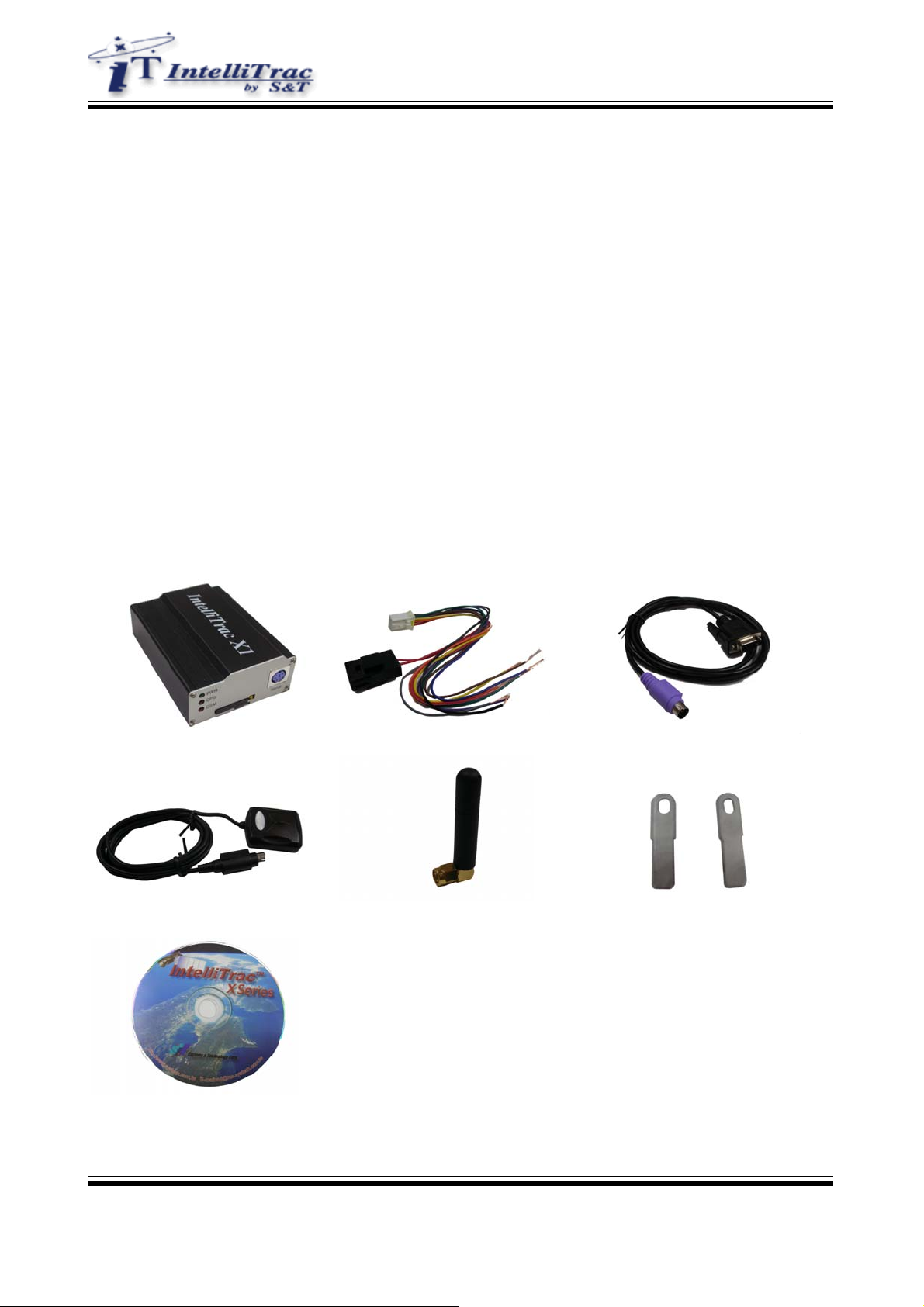
33 PPrroodduucctt CCoonntteennttss
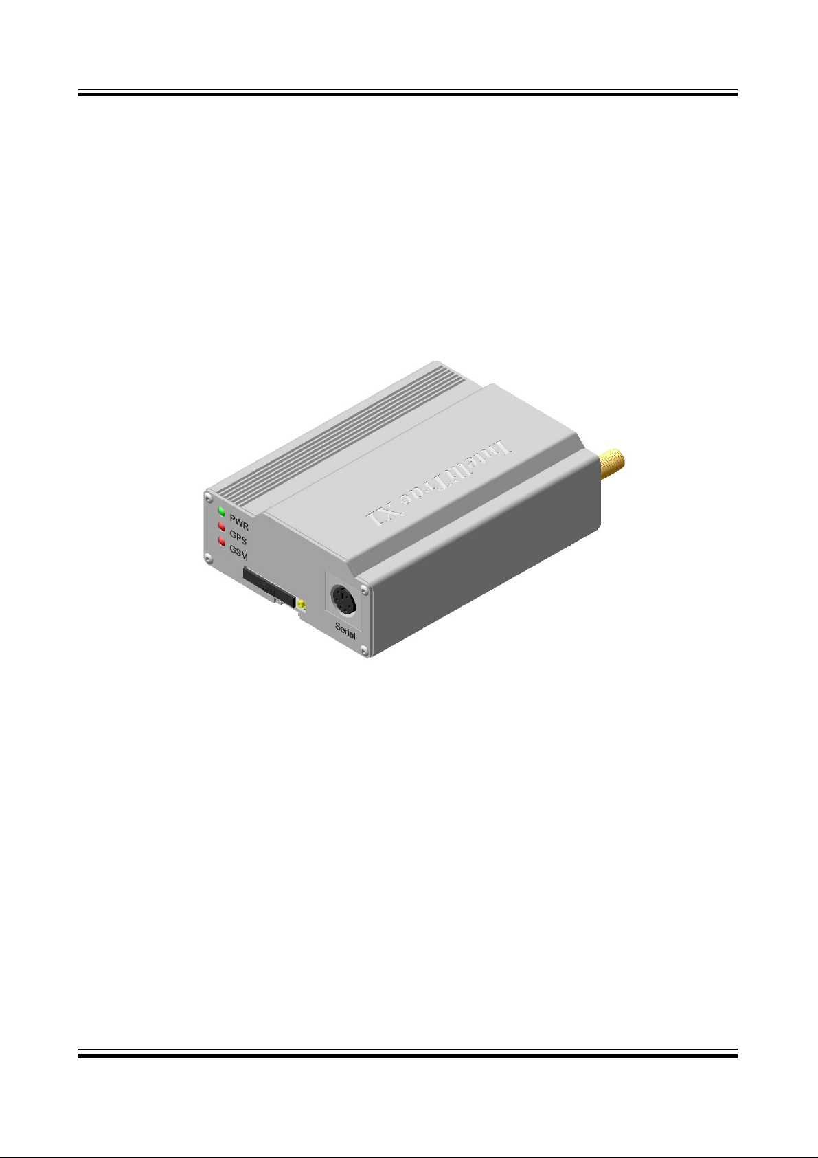
IntelliTrac X1-PRO device Power I/O Cable Serial Cable
GPS Receiver GSM/GPRS Antenna Holding Bridles
CD (User manual & Software)
© Systems & Technology Corp. All rights reserved.
- 1 -
IntelliTrac X1-PRO User’s Manual
44 HHaarrddwwaarree IInnssttaallllaattiioonn
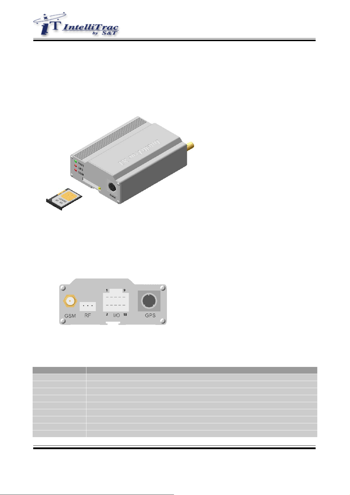
4.1 Install SIM card
Press the yellow button to enject the SIM card holder and insert the SIM card. If you would like to disable
the PIN code, please use general GSM cellular phone to disable the PIN code in advance.
4.2 Install Cables
z Install I/O cable
The I/O cable is a 10-wires cable which include power and positive/negative input s and outputs.
The I/O cable pins assignment shown below :
Pin Number Description
1 DC power source ( 8V ~ 30V )
2 Ground
3 Input1 (ACC Positive trigger input)
4 Output1
5 Input2 (Positive trigger)
6 Output2
7 Input3
8 Output3
9 Input4
© Systems & Technology Corp. All rights reserved.
- 2 -

IntelliTrac X1-PRO User’s Manual
10 Output4 (Internal 2A Relay)
z Install GSM Antenna
Connect the GSM antenna to the SMA conne ctor with lable “GSM”.
z Install GPS Receiver
Connect the GPS receiver to the Mini DIN connector with label “GPS”. Use a nylon cable tie to prevent
unexpected come off.
z Install RF Receiver (Optional)
Connect the RF receiver ti the 3 pins connector with label “RF”.
4.3 Mounting the unit
For mounting the unit, bind to the body the holding bridles according the the schema below :
© Systems & Technology Corp. All rights reserved.
- 3 -
IntelliTrac X1-PRO User’s Manual
55 SSooffttwwaarree IInnssttaallllaattiioonn
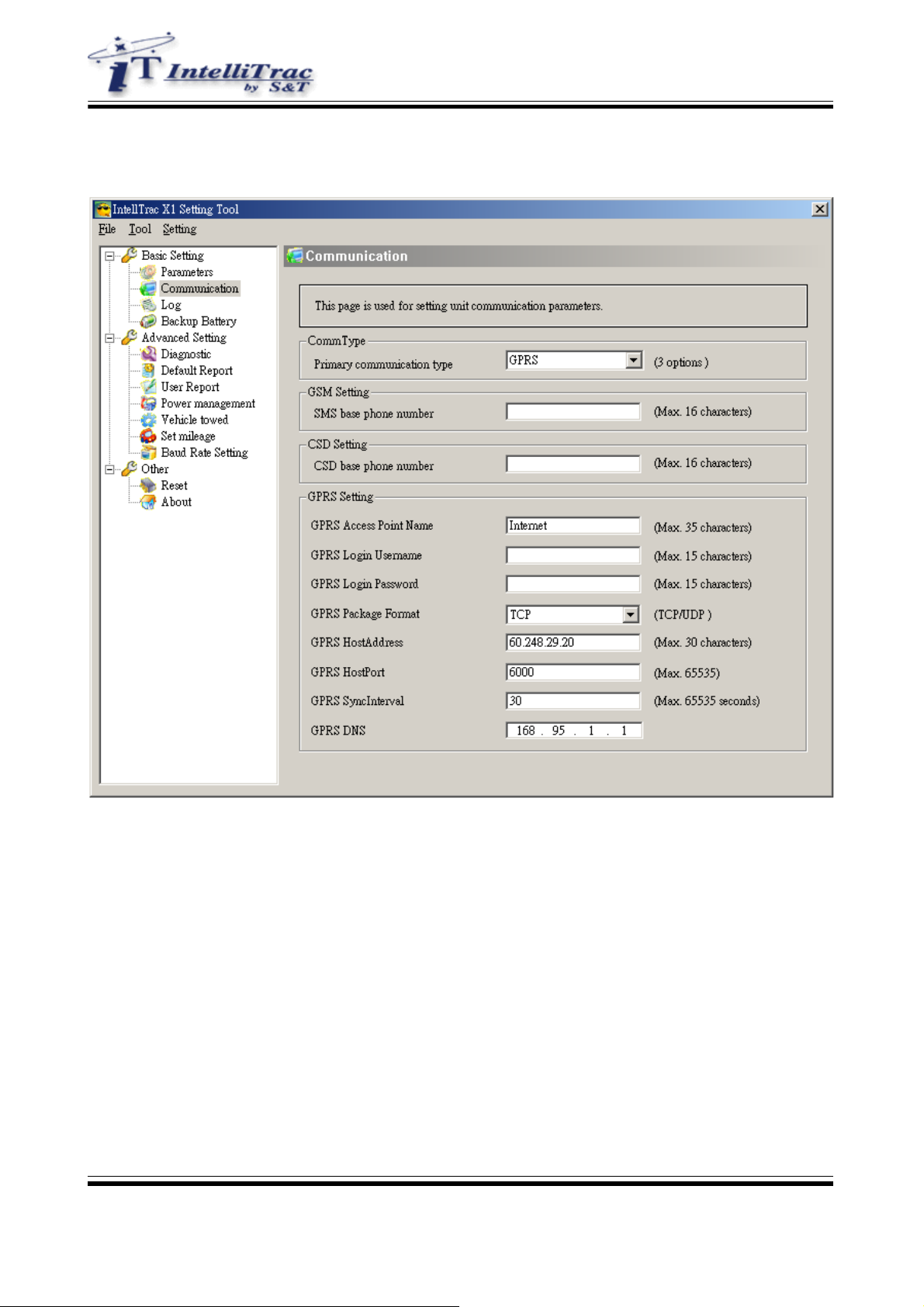
5.1 Configuration Software
© Systems & Technology Corp. All rights reserved.
- 4 -

5.2 Firmware Download Software
IntelliTrac X1-PRO User’s Manual
© Systems & Technology Corp. All rights reserved.
- 5 -

IntelliTrac X1-PRO User’s Manual
66 SSppeecciiffiiccaattiioonnss
Dimension 90mm x 70mm x 30mm
Weight 250g
Input Ports 4 Inputs (2 positive, 2 negative)
Output Ports 4 Outputs (4 negative trigger)
GPS Datum WGS-84
GPS Frequency L1, 1575.42MHz
GPS Channel 20
GPS Tracking sensitivity -159dBm typ.
GPS Cold Start 40secs
GPS Warm Start 25secs
GPS Hot Start 3secs
GPS Update Rate 1Hz
GPS Accuracy 3m CEP (50%), 7m (90%)
GPS Baud Rate 19200bps
GSM/GPRS Frequency Tri-Band 850/1800/1900MHz
GPRS Multi-slot class 10
SMS PDU mode
Data mode CS Data
Voice mode HR/FR/EFR
77 EElleeccttrriiccaall cchhaarraacctteerriissttiiccss
7.1 Absolute maximum ratings
Absolute maximum rating for power supply and voltage on digital input pins of the IntelliTrac X1-PRO are list
in following table:
Parameter Min Max Unit
Supply Voltage 8 30 V
Positive trigger Input Voltage 5 30 V
Positive trigger Input current 35 uA
Negative trigger Input Voltage 0 0.7 V
Output current 400 mA
Relay output current 2 A
Power current consumption (Standby mode) 40 45 mA @ 12VDC
Power current consumption (GPS Off mode) 24 26 mA @ 12VDC
Power current consumption (Deep sleep mode) 15 15 mA @ 12VDC
7.2 Operating temperatures
The operating temperature is listed in following table:
Parameter Min Typ Max Unit
Ambient temperature -20 25 55
Restricted temperature* -20 ~ -40 55 ~ 85
Storage Temperature -40 85
℃
℃
℃
*The IntelliTrac X1-PRO device can work, but the deviation from the specification may occur.
© Systems & Technology Corp. All rights reserved.
- 6 -

7.3 LED Indicators
PWR LED Status Function
Off Power off
20 ms On / 2 secs Off The device is running in power saving mode.
500ms On / 500ms Off Reset procedure is in progress
20ms ON / 20ms Off Upgrade firmware is in progress
On Power on
GPS LED Status Function
Off The GPS is of f or running in power saving mode.
1 sec On / 1 sec Off No GPS satellites signal received
On GPS Ready
IntelliTrac X1-PRO User’s Manual
GSM LED Status Function
Off The device is off or running in deep sleep mode.
600 ms On / 600ms Off No SIM card inserted or no PIN entered, or network search in
progress, or network login in progress.
90 ms On / 3 secs Off Logged to network.
90 ms blinking 2 times
/3secs Off
GPRS Network connected
© Systems & Technology Corp. All rights reserved.
- 7 -

IntelliTrac X1-PRO User’s Manual
88 AAbboouutt SSyysstteemmss && TTeecchhnnoollooggyy CCoorrppoorraattiioonn
IntelliTrac X Series AVL device is produced by Systems & Technology Corporation. The company is a key
developer and supplier of advanced systems in the Automatic Vehicle Location (AVL), Digital Map and Car
Navigation Systems.
If you need information on other maps solutions or products, please contact us at the phone and fax
numbers listed below, or visit our web sites.
Contact Information for System & Technology Corp.
S&T Web Site
Technical Support Hotline 886-2-26981599
Technical Support E-mail
Main Phone 886-2-26981599
Main Fax 886-2-26981211
http://www.systech.com.tw
A V L@ms.sy stech.com.tw
WARNING:
This device complies with part 15 of the FCC Rules. Operation is subject to the following two conditio ns: (1)
This device may not cause harmful interference, and (2) this device must accept any interference received,
including interference that may cause undesired operation.
zThis device has been tested and found to comply with the limits for a Class B digital device, pursuant to
Part 15 of the FCC Rules. These limits are designed to provide reasonable protection against harmful
interference in a residential installation. This equipment generates, uses and can radiated radio frequency
energy and, if not installed and used in accordance with the instructions, may cause harmful interference to
radio communications. However, there is no guarantee that interference will not occur in a particular
installation If this equipment does cause harmful interference to radio or television reception, which can be
determined by turning the equipment off and on, the user is encouraged to try to correct the interference by
one or more of the following measures:
-Reorient or relocate the receiving antenna.
-Increase the separation between the equipment and receiver.
-Connect the equipment into an outlet on a circuit different from that to which the receiver is connected.
-Consult the dealer or an experienced radio/TV technician for help.
Changes or modifications not expressly approved by the party responsible for complian ce could void the
user‘s authority to operate the equipment.
© Systems & Technology Corp. All rights reserved.
- 8 -
 Loading...