

Intellisystem TT-1009CNL-DVIPCS, TT-1018CNL-DVIPCS, TT-1075CNL-DVIPCS, TT-1037CNL-DVIPCS, TT-1050CNL-DVIPCS User Manual
Page 1
ThermalTronix
TT-CNL-DVIPCS Series
User Manual
Page 2

1
Warnings & Attention
Please avoid aiming the lens at extreme high temperature radiation source, such as the sun,
molten steel or laser in any situation; otherwise the detector may be damaged.
Please do not touch the lens to avoid contaminating and damaging. Please pay attention to
protect the lens to avoid causing abrasion, scratches even breaches, otherwise, it will affect
the device performance badly, even damage the device.
This device is a precise optoelectronic product. Please protect it properly during usage,
storage and transportation, where improper use (such as drop and collision) will cause
damage to the device. If the internal connection is broken during the assembly process or
the apparatus is damped (rain wet), the performance will be reduced and even the device
will be damaged.
Make sure that the power control connection is reliable. If the power control wire is in bad
connection, it will damage the device.
Ensure the proper connection of power control cable and data cable. Wrong connection may
cause damage to the device.
Do not swag fiercely or collide the device during transportation, otherwise it will cause
performance-reduction and even damage to it.
Please use the specified power supply; otherwise it will cause improper working, even
damaging the apparatus.
If the product works abnormally, please contact the dealer or the nearest after-sale service center.
Please do not dismantle or replace it in any manners.
Page 3

2
CONTENTS
1 OVERVIEW......................................................................................................................................... 3
1.1 FEATURES ................................ ................................................................................................ ........ 3
2 ELECTRICAL CONNECTIONS ...................................................................................................... 4
2.1 CONNECTING POWER ....................................................................................................................... 4
2.2 ETHERNET CONNECTION .................................................................................................................. 4
3 QUICK START OF THE IVMS SOFTWARE ................................................................................. 5
3.1 STARTING VMS CLIENT SOFTWARE ................................................................................................ 5
3.2 WIZARD FOR IMPORTING DEVICE .................................................................................................... 5
3.3 LIVE VIEW ..................................................................................................................................... 11
3.4 CAMERA CONTROL ........................................................................................................................ 12
4 THERMAL CAMERA CONFIGURATION MENU ...................................................................... 17
4.1 MAIN MENU ................................................................................................................................... 17
4.2 SUB MENU ..................................................................................................................................... 19
5 TECHNICAL SPECIFICATIONS ................................................................................................... 23
Page 4

3
1 Overview
1.1 Features
1. Provider good image quality in total darkness.
2. Multiple optional lenses for thermal camera, meet different requirements of surveillance
distance 3.2MP high-resolution visible light camera, 20X optical zoom.
3. Easy integration into IP network, support multiple network and PTZ control protocols, video
transmission over Ethernet.
4. IP66 encapsulation suitable for operation in extreme environmental conditions.
Page 5

4
2 Electrical connections
2.1 Connecting power
The camera itself does not have an on/off switch. Connect AC24V power supply, if power is
supplied to it, the camera will be Powered On.
Note: Generally the camera will be connected to a circuit breaker and the circuit breaker will be
used to apply or remove power to the camera.
2.2 Ethernet connection
The camera provides a standard RJ 45 Ethernet jack. It can be easy integrated into any existing IP
network. Video and control command transmission over Ethernet.
Page 6
5
3 Quick Start of the IVMS software
3.1 Starting VMS Client Software
Note: This chapter only introduce some basic function, more specifics and functions, pls check
“VMS- Client software User Manual”(refer to chapter 3.2:click help, and open user manual).
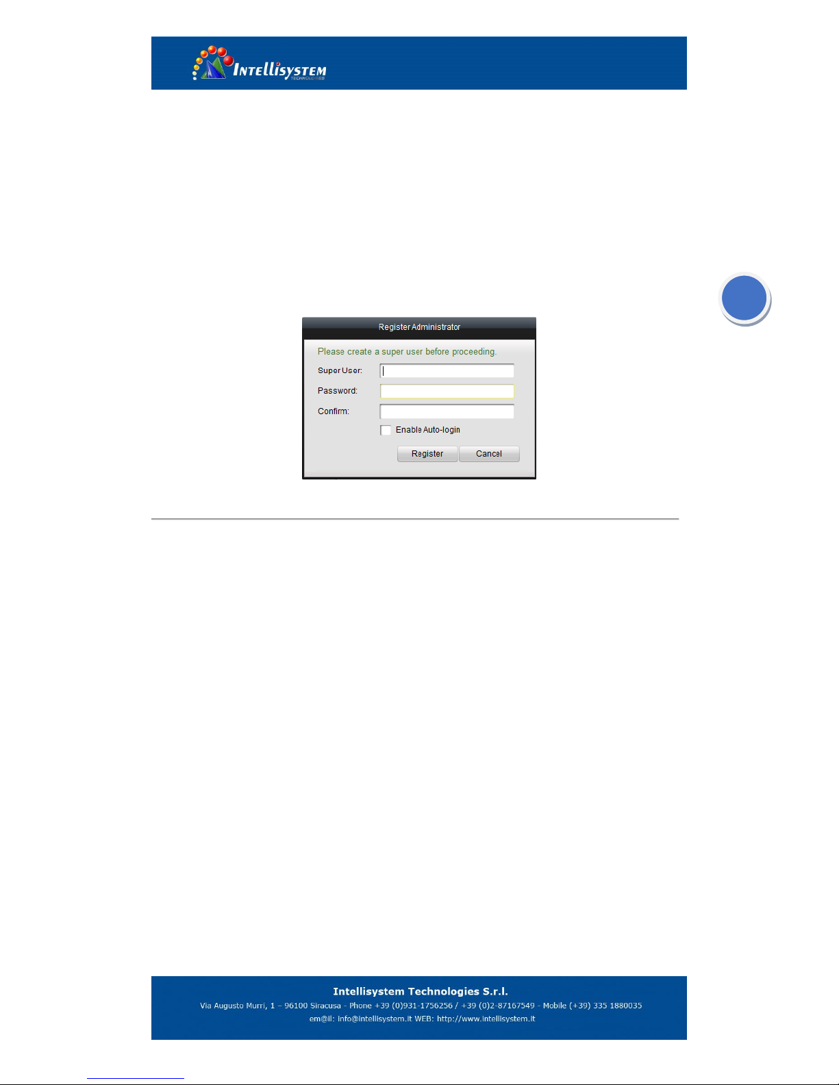
Install the VMS- software on your PC according to the prompts. For the first time to use the VMS
software, you need to register a super user for login.
Register User
Enter the super user name, password, confirm the password in the dialog box, and click Register.
Then, you can log in as the super user.
Note: Enter, Space, and TAB keys are invalid for the user name and password. The password
cannot be empty, and it should not be less than six characters and cannot be copied and pasted.
3.2 Wizard for Importing Device
The main function of the VMS is to manage network devices remotely. Thus, the task on the top
hierarchy is to register the device to the management list.
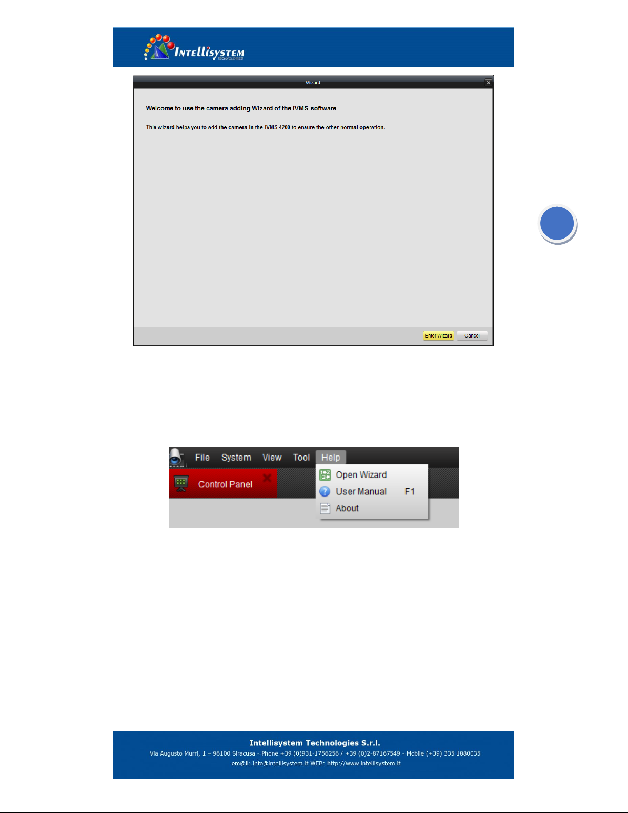
For the first time user, the wizard message box pops up to ask you whether you want to be
guided for the basic operation of the client software.
Page 7
6
Wizard
If this is not the first time, you use the client software, the wizard does not pop up, and you can
use the wizard, click Help and Open Wizard (or user manual if necessary).
Open wizard and User Manual
Click [Entering Guide] to start the wizard, or click Cancel to exit the wizard.
Steps:
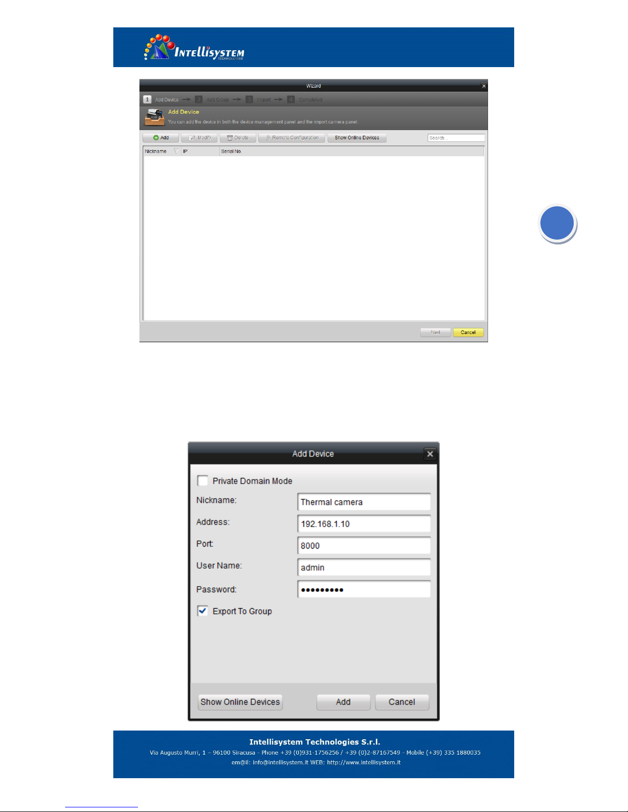
1. According to the hint, click Add icon to add devices to the management list of the
software.
Page 8
7
2. Create a nickname for the device, enter the IP address and the port number of the remote
device, enter the user name, and the password of the device.
Note: Default IP address marked on the rear of camera
Default user name: admin
Default password: 123456
Page 9

8
3. Click Add icon to add the device.
You can also click Show online device to show the device connected to the same Local Area
Network.
Adding the active online devices
Steps:
1) Select the device in the device list, and the information of the device such as the MAC address
the software version and the serial number is shown in the left part. The information in this part
cannot be modified.
2) In the Network information area, you can modify the IP address the Subnet Mask and the Port
number with entering the admin password of the device.
Note: Default password: 123456
3) You can also recover the default password for the device, with the code provided by the
authorized engineers.
Page 10

9
4.) Adding Camera Group
When adding a device, you can check the Export to group checkbox to export the device you
added to certain camera group.
By default, the name of the group is the same with the name of the device you just added.
If you want customize the camera choosing for the group and the group name. You uncheck the
Export to Group checkbox and click Next page on the Wizard, to enter the adding group
interface.
Click Save to add a new user. Click Modify to change the settings for the new user.
Page 11

10
Click the on Group dialog box. Edit the name of group and then click OK to save your
settings. The added group will be displayed in the list.
5). Import Channels to Group In the left area on the Camera Import interface, click to select the
channels and then click Import button to import the selected channels to the Group on the right.
6). You can drag and select multiple channels to import them to the group you added.
Note:
The devices to be added must be online currently.
One channel can be added to different groups.
Up to 256 groups can be added, and 64 channels can be added to each group, with a
maximum of 1024 channels for all the groups totally. After importing the selected channels
to the group, you can return to the control panel and then enter the Main View interface to
get a live view of the added channels.
Page 12

11
3.3 Live view
Entering the Live View Interface:
Click the main view icon on the control panel, or click View -> Main View on the toolbar to
enter the live view interface.
The main view interface is shown in the following figure:
To view the live video, drag the camera from the list to the display window, or double click the
camera name after you select one screen.
Page 13

12
3.4 Camera control
A. How to set camera control configuration
Click the icon on the toolbar on the screen for camera or click the right button of the mouse
to pop up the menu.
Camera setting option
Page 14

13
On the PTZ parameters configuration page, you can specific the camera connection
parameters, such as baud rate, data bit, PTZ protocol and PTZ address. The info (including IP
address) marked on the rear of the housing.
Note: The default setting (Baud rate: 2400; Protocol: PELCO-D; PTZ address: 2)
Click save button to save the changes
PTZ parameters configuration
B. how to communication with thermal camera
After configure the PTZ parameters, click the icon on the toolbar on the screen for thermal
camera or click the right button of the mouse to pop up the menu, and the PTZ control panel will
be displayed on the left side of the Main View.
Page 15

14
PTZ control option
PTZ control toolbar
PTZ control panel display on the left side of the main view
Page 16

15
Camera control board PTZ control board
Button
Description
Zoom: N/A
Zoom-: Digital zoom(shortcut key)
Zoom+: Alarm switch(shortcut key)
Focus: N/A
Focus-: When there is a menu, modify the option or
reduce the value
Focus+: When there is a menu, modify the option or
increase the value
Iris: N/A
Iris-: When there is a menu, move the cursor from up to
down
Iris+: Uniformity calibration manually(shortcut key)
Preset configuration
Calling function
Calling preset 100 to pop up the menu
Note: The camera will do the uniformity calibration automatically every 20 minutes when the
working time more than 2 hours. You can also operate the calibration manually (Iris+ command),
when camera receives the command, the lens will be covered by internal shutter, then image
display nothing as below figure, after approx 0.5 second, the image display become normally.
FOCUS Tool bar
IRIS Toolbar
ZOOM Toolbar
Page 17

16
The image in calibration procedure
C. Pop up the thermal camera configure menu:
Select a PTZ preset number from the preset list, and double click preset 100 or click to
call preset 100, the camera configure menu display on the image.
PTZ preset setting
Page 18

17
4 Thermal camera configuration menu
4.1 Main menu
After pop the menu via call preset 100, the menu display on the bottom of the image:
Press key “IRIS-” move the cursor,Press key “FOCUS+” or “FOCUS-” to change the value
where the cursor is. Auto save when exit
1、Auto: XXX Display the current image auto mode. Three options:
0: manual gain, manual brightness;
1: manual gain, auto brightness;
2: auto gain, auto brightness; ( Factory default )
2、G: XXX Gain value, range: 1~1023;
3、B: XXX Brightness value, range
4、P: XXX White/black hot display mode
0: black hot 1: white hot
Page 19

18
Black hot White hot
5、ZOOM:Y/N Zoom status
N:no zoom(default) Y:Zoom 2 times
No zoom Zoom 2 times
6、Level: X show the level of alarm:From 1 to 6, default is 4.Alarm feature was invalid in this
system
7、Setting: Press key “FOCUS+” or “FOCUS-”,show the password dialogue
Press “FOCUS-、FOCUS+、FOCUS-、FOCUS+、FOCUS-、FOCUS+” to enter sub menu dialogue
8. EXIT: Exit the menu
Note:
1) All parameters are save automatically after exit
2) The camera will run the last setup after reboot
Page 20

19
4.2 Sub menu
In the main menu, move the cursor to “Settings “option ,press ”Focus+”or “Focus-” show the
password dialogue, input the password “FOCUS-、FOCUS+、FOCUS-、FOCUS+、FOCUS-、
FOCUS+” to enter.
Password dialogue
Sub menu
Press key “IRIS-” move the cursor ,Press key “FOCUS+” or “FOCUS-” to change the value
where the cursor is 。Auto save when exit
Page 21

20
1 COM option:
Press key “FOCUS+” or “FOCUS-” show the password dialogue,Input the password “FOCUS-、
FOCUS+、FOCUS-、FOCUS+、FOCUS-、FOCUS+” enter the “COM” option
In the menu “COM”,Press key “IRIS-” move the cursor ,Press key “FOCUS+” or
“FOCUS-” to change the value where the cursor is 。Auto save when exit
(1) ID:XXX ADD:0~254。
(2) Baud Rate:XXX Baud :1200,2400,4800,9600,14400,19200,38400。
(3) Protocol: PELCO-D/P。
(4) Exit: Press key IRIS+ to exit
Default:Add:1 Baud:2400 Protocol: PELCO-D
2 Mode option:
Press key “FOCUS+” or “FOCUS-” show the password dialogue,Input the password “FOCUS-、
FOCUS+、FOCUS-、FOCUS+、FOCUS-、FOCUS+” enter the “Mode” option.
Page 22

21
In the menu “Mode”,Press key “IRIS-” move the cursor ,Press key “FOCUS+” or “FOCUS-” to
change the value where the cursor is 。Auto save when exit
(1) Gain:XXX Range: 0~255。
(2) Bright:XXX Range: 0~255。
(3) Exit: Press key IRIS+ to exit
Default:G:32 B: 188
3 Alarm Valve:
Invalid in this system
4 Debug:
Use to debug the firmware, do not open to end-user
5 Recover :H/L/N
Setup as H /L/N;
Page 23

22
Setup as H:Calibrate 1 time during the 1 minute if working time less than 10 minutes. Calibrate 1
time during 2 minutes if working time between 10 and 30 minutes. Calibrate 1 time during 5
minutes if working time between 30 minutes and 1 hour. Calibrate 1 time during 10 minutes
if working time more than 1 hour. Calibrate 1 time during 20 minutes if working time more
than 2 hours.
Setup as L:Calibrate 1 time during the 1 minute if working time less than 0 minute. Calibrate 1
time during 2 minutes if working time between 10 and 30 minutes .calibrate 1 time during 5
minutes if working time more than 30 minutes.
Setup as /N:Calibrate manually ;
6 Image: H/M/L
Setup as high/middle/low;
Each grade relatively corresponds to a value of image quality, default is middle
7 Alarm:X
Show the status of gray alarm :N/Y
N: off;( Default) Y: On
8 E:X
Show the status of image enhancement,setup as C/1/2;
C: Close;( default) 1/2:Open relatively Gain grade
9 Backup:
Factory default ,including auto,polarity,alarm range,calibration,image,alarm,
alarm pixel Number。
10 Exit :XXX
Press key “FOCUS+” or “FOCUS-” to exit
Page 24

23
5 Technical Specifications
Items
ThermalTronix TT-CNL-DVIPCS Series
Detector
Characteristics
Detector type
Un-Cooled FPA Micro-Bolometer
Resolution
384*288
Detector pitch
25μm
Frame rate
50HZ
Image
Characteristics
Lens
61.1°×45.8°(9mm)
30.6°×22.9°(18mm)
14.8°×11.1°(37mm)
11°×8.2° (50mm)
7.3°*5.5°(75mm)
TT-1009CNL-DVIPCS
TT-1018CNL-DVIPCS
TT-1037CNL-DVIPCS
TT-1050CNL-DVIPCS
TT-1075CNL-DVIPCS
NETD
≤100mk
Focus Range
Athermalized, focus-free
Functions
Brightness/gain control
Manual brightness/gain; Automatic brightness/manual
gain; Automatic brightness/gain
Automatic brightness/gain
configuration adjustment
2 fixed patterns, 8 users from definition establishment
pattern
Polarity reversal
Black hot/White hot
Electronic zoom
2x
Noise reduction function
Yes
Image intensification
function
Yes
Calibration
Auto/Manual calibration
CCD Camera
Resolution
1920×1080
Imaging Device
1/2.8″ Progressive Scan CMOS
Lens
4.7-94mm (F1.6-3.5), 20x optics
PTZ
Horizontal rotation degrees
0°~360° continuous rotation
Vertical rotation degrees
-90°~+90°
Horizontal rotation speed
0. 1°~9°/S
Vertical rotation speed
0.1°~4°/S
Preset
80
Heater
YES
Fan
YES
Interface
Video Over Ethernet
RJ45
Video compression
IR video (H.264/MPEG4/MPEG2/MJPEG)
CCD video (H.264/MPEG4)
Protocols
TCP/IP ,IPv4/v6,HTTP,OnVIF,PTZ control protocols
General
Voltage
AC24V
Power Consumption
<200W (including heating)
Operating temperature
-40℃~ +50℃
Storage temperature
-45℃~ +70℃
Protection
IP66
Weight
≤20Kg
Dimensions
500mm(L)×350mm(W)×300mm(H)
 Loading...