

Intellisystem Technologies S.r.l. http://www.intellisystem.it
IT750/IT750W/IT750W-LR
Network Camera with Pan/Tilt/Zoom
Quick Installation Guide
This guide describes the basic functions of
IT750/IT750W/IT750W-LR Network Camera.
All detailed information is described in the
user's manual.

Warning Before Install
1
Intellisystem Technologies S.r.l. http://www.intellisystem.it
IT750/IT750W/IT750W-LR Quick Start Guide

2
Intellisystem Technologies S.r.l. http://www.intellisystem.it
IT750/IT750W/IT750W-LR Quick Start Guide
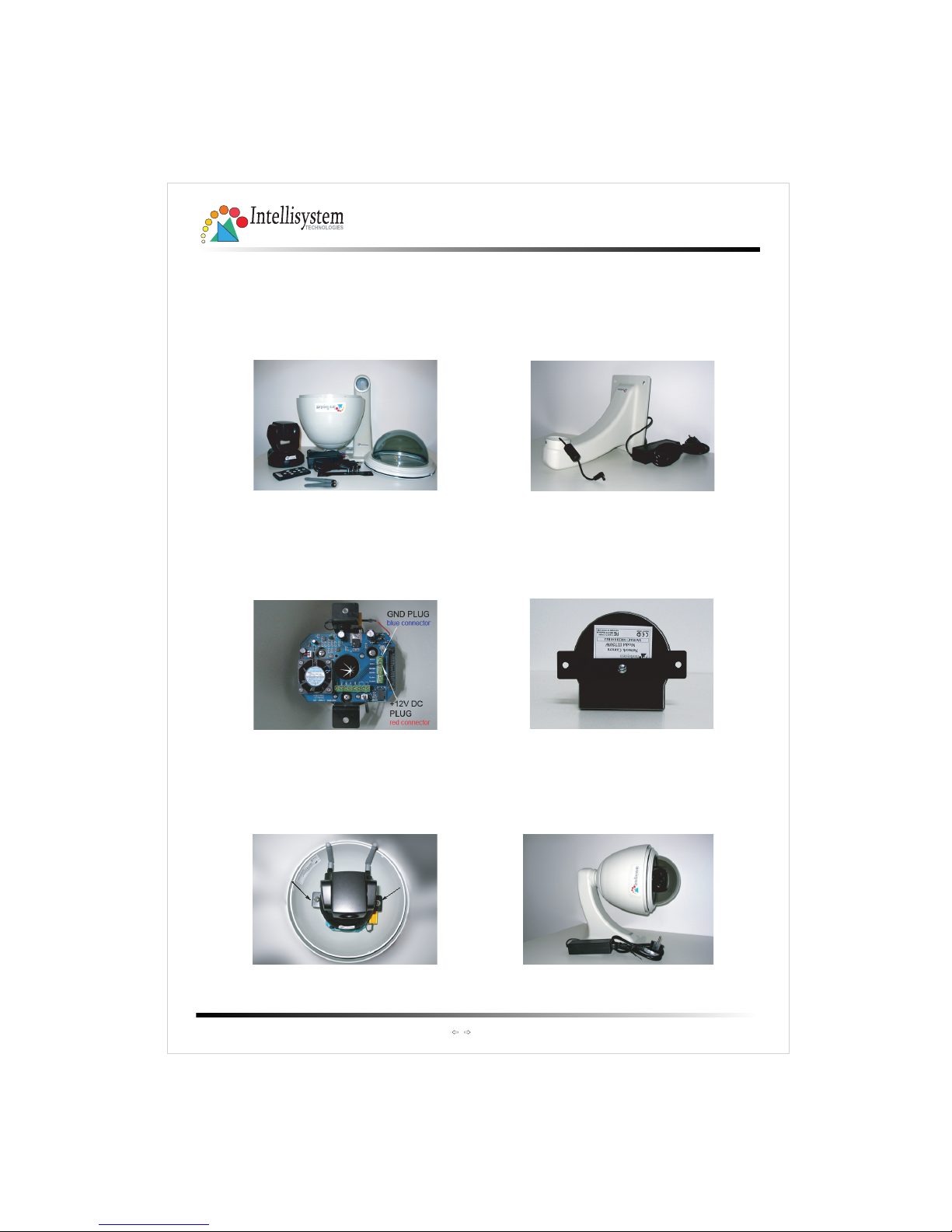
IT750 Aluminium Housing Assembling
Components: Step 1: Get the power wire through the
bracket first.
Step 5: Finally cover up, and the
assembling is accomplished.
Step 2: Then through out from the housing
part, meanwhile insert the power cable
to the appropriate socket. (P.S. This device
is suitable for AC or DC input, no negative
or positive discriminate)
Step 4: Screw on the two side screws, and
plug in the power of the dome.
(1) Bracket
(2) Cover
(3) Housing
(5) Dome
(5) Remote controller
(4) Power
Screw on
Screw on
Step 3: Screw the dome on the
fixing bridge.
3
Intellisystem Technologies S.r.l. http://www.intellisystem.it
IT750/IT750W/IT750W-LR Quick Start Guide
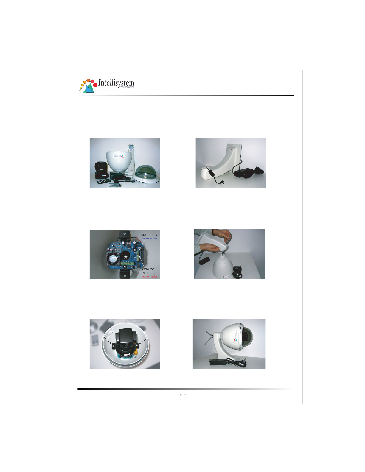
IT750W Aluminium Housing Assembling
Components: Step 1: Get the power wire through the
bracket first.
Step 5: Finally cover up, and the
assembling is accomplished.
Step 2: Then through out from the housing
part, meanwhile insert the power cable
to appropriate socket. (P.S. This device
is suitable for AC or DC input, no negative
or positive discriminate)
Step 4: Screw on the two side screws, and
plug in the power of the dome.
(1) Bracket
(2) Cover
(3) Housing
(5) Dome
(4) Power
(6) Antennas
Screw on
Screw on
Step 3: Screw the dome on the
fixing bridge.
(5) Remote
controller
4
Intellisystem Technologies S.r.l. http://www.intellisystem.it
IT750/IT750W/IT750W-LR Quick Start Guide
IT750W-LR Aluminium Housing Assembling
Components: Step 1: Get the power wire through the
bracket first.
Step 5: Finally cover up, and the
assembling is accomplished.
Step 2: Then through out from the housing
part, meanwhile insert the power cable
to the appropriate socket. (P.S. This device
is suitable for AC or DC input, no negative
or positive discriminate)
Step 4: Screw on the two side screws, and
plug in the power of the dome.
(1) Bracket
(2) Cover
(3) Housing
(5) Dome
(4) Power
(6) Antennas
Screw on
Screw on
Step 3: : Pass the cables of two antennas
through the holes in the bracket
screw on the antennas.
housing part into the
Attention to the cables inside!
and
Screw
bracket.
(5) Remote
controller

5
Intellisystem Technologies S.r.l. http://www.intellisystem.it
Check package contents
1
Home
Auto-Patrol Auto-Pan Center
Stop
IT750/IT750W/IT750W-LR Quick Start Guide
Remote controller
Wired or Wireless Network Camera
Software CD
Power Adapter
Antennas (for wireless
models only)
6
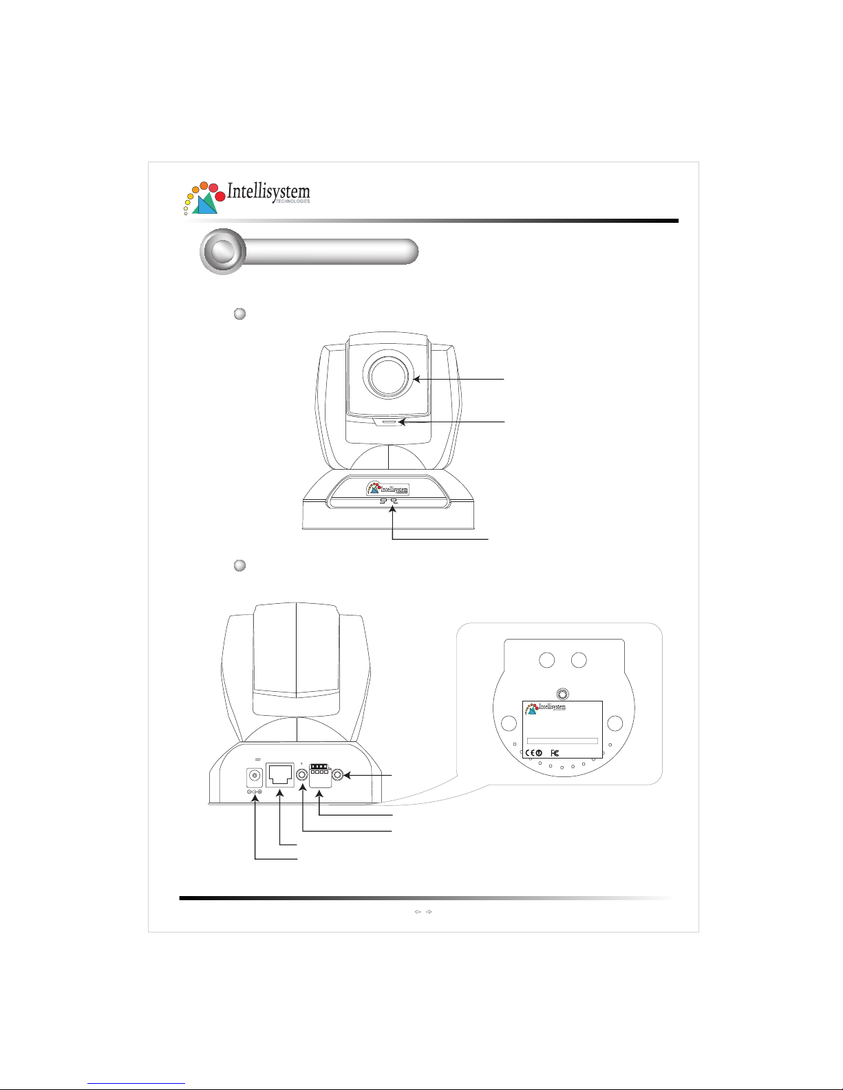
Physical description
2
Rear panel
Activity
Power/MIC
Lens
Status LED
Microphone
ETHERNET
MIC
EXT.I/O
AV
OUT
12V
1.5A
Ethernet 10/100 RJ45 socket
Power cord socket
External Mic.
EXT I/O
A/V out
Note the serial number on the label of the unit.
The serial number is the same as Ethernet address,
for example: 0002D1455282=00-02-D1-45-52-82.
Made in Taiwan
SN/MAC: 0002D001XXXX
Network Camera
Model IT750
Intellisystem Technologies S.r.l. http://www.intellisystem.it
IT750/IT750W/IT750W-LR Quick Start Guide
Front panel

1
2
V
1
.
5
A
E
T
H
E
R
N
E
T
M
I
C
E
X
T
.
I
/
O
A
V
O
U
T
7
3
Install the Network Camera in Ethernet network
3.Finally, connect the power cord to a power
outlet.
P
O
W
E
R
C
O
L
L
I
S
I
O
N
L
I
N
K
R
E
C
E
I
V
E
P
A
R
T
I
T
I
O
N
1
2
3
4
5
2.
Use an Ethernet cable to make
connection from the Ethernet port
to the hub.
If external devices such as sensors
and alarms are available, make
connection to the I/O terminal block.
Refer to the user's manual for the
I/O voltages.
Use a categoty 5 cross cable
when the Network Camera is
directly connected to a PC.
Intellisystem Technologies S.r.l. http://www.intellisystem.it
IT750/IT750W/IT750W-LR Quick Start Guide

Assign IP address
4
8
1.Run the "Network Camera Wizard" under "Utilit y" directory on the
soft ware CD.
3.After searching, the main
installer window will pop up.
Click on th e serial number
that matches th e one you
just noted from
Physical description
2
2.The program will search Video Servers or Network Cameras on the same
LAN.
4.Click "Link to selected
device(s)" to connect the
Internet Explorer to the
Network Camera.
If there is no DHCP server on
the LAN, please refer to the
user's manual for th e
methods of assigning an IP
address.
Intellisystem Technologies S.r.l. http://www.intellisystem.it
IT750/IT750W/IT750W-LR Quick Start Guide

9
Intellisystem Technologies S.r.l. http://www.intellisystem.it
IT750/IT750W/IT750W-LR Quick Start Guide
The Internet Explorer Connects to the Network Camera
5
For further setup, please, check the user's manual on the software CD.
10
IT750/IT750W/IT750W-LR Quick Start Guide
Intellisystem Technologies S.r.l. http://www.intellisystem.it

11
IT750/IT750W/IT750W-LR Quick Start Guide
Intellisystem Technologies S.r.l. http://www.intellisystem.it

12
IT750/IT750W/IT750W-LR Quick Start Guide
Intellisystem Technologies S.r.l. http://www.intellisystem.it

13
IT750/IT750W/IT750W-LR Quick Start Guide
Intellisystem Technologies S.r.l. http://www.intellisystem.it
IT750/IT750W/IT750W-LR Quick Start Guide
14
Intellisystem Technologies S.r.l. http://www.intellisystem.it
IT750/IT750W/IT750W-LR Quick Start Guide
15
Intellisystem Technologies S.r.l. http://www.intellisystem.it
 Loading...