

Page 1
IT3G520/IT3G520W/IT3G520W-LR
Network Camera
Quick Installation Guide
This guide describes the basic functions of
IT3G520/IT3G520W/IT3G520W-LR Network Camera.
All detailed information is described
in the user’s manual.
In te llisy ste m Te ch n o lo g ie s S.r.l. - h tt p ://w w w .i nte llisy ste m .it
Page 2
IT 3G 5 20 /IT 3G 5 20 W /IT 3G 5 20W -L R Q u ick Start G u id e
In te llisy ste m Te ch n o lo g ie s S.r.l. - h tt p ://w w w .i nte llisy ste m .it
Page 3

In te llisy ste m Te ch n o lo g ie s S.r.l. - h tt p ://w w w .i nte llisy ste m .it
IT 3G 5 20 /IT 3G 5 20 W /IT 3G 5 20W -L R Q u ick Start G u id e
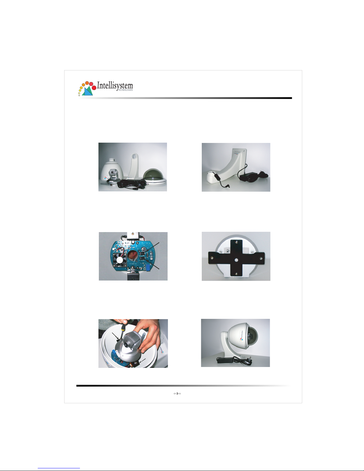
IT 3G520 Aluminium Housing Assembling
Components: Step 1: Get the power wire through the
bracket first.
Step 5: Finally cover up, and the
assembling is accomplished.
Step 2: Then through out from the housing
part, meanwhile insert the power
cable to the appropriate socket.
Step 4: Screw on the two side screws, and
plug in the power of the dome.
(1) Bracket
(2) Cover
(3) Housing
(5) Dome
(4) Power
Screw on
Screw on
Step 3: Screw the dome on the
fixing bridge.
Power
Camera
Page 4
In te llisy ste m Te ch n o lo g ie s S.r.l. - h tt p ://w w w .i nte llisy ste m .it
IT 3G 5 20 /IT 3G 5 20 W /IT 3G 5 20W -L R Q u ick Start G u id e
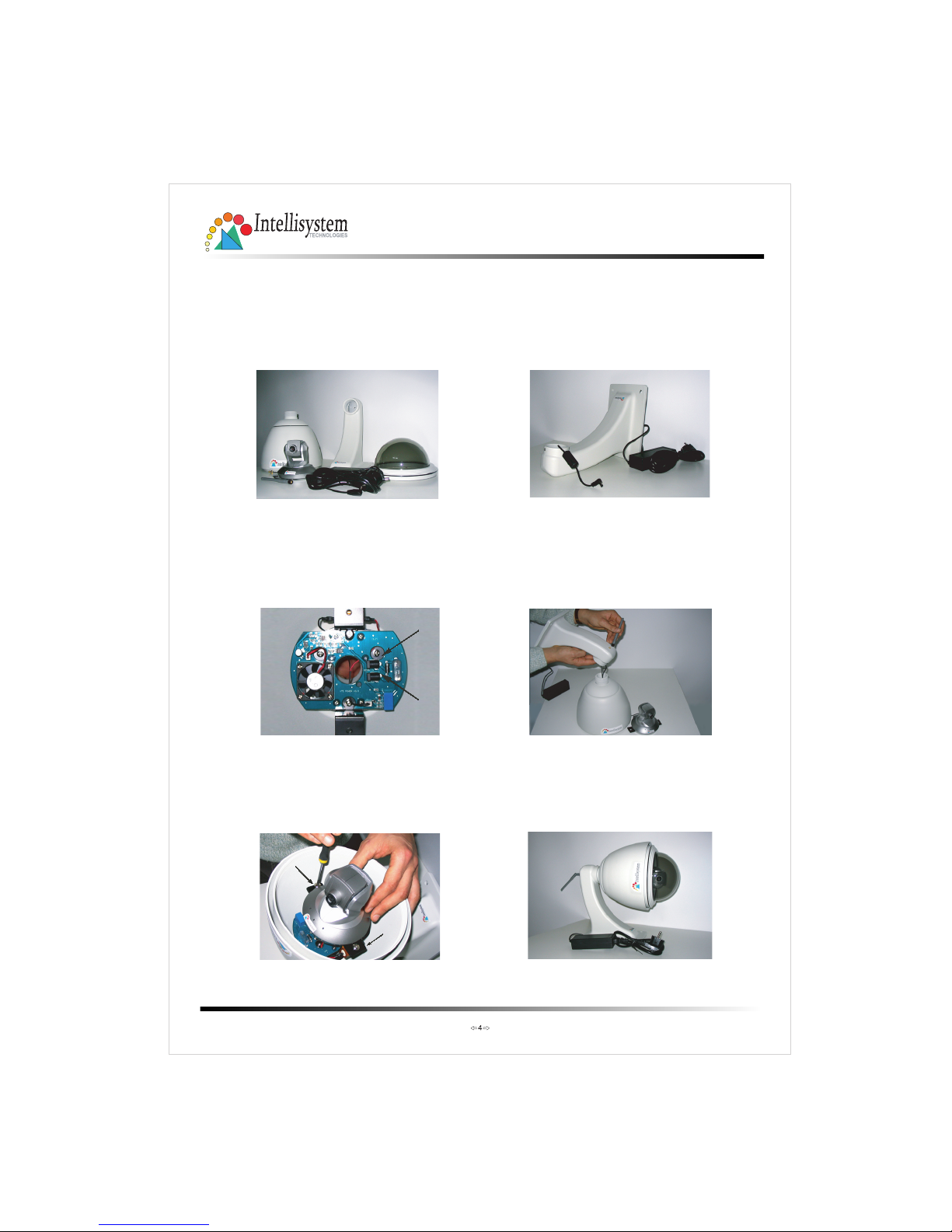
IT 3G520W Aluminium Housing Assembling
Components: Step 1: Get the power wire through the
bracket first.
Step 5: Finally cover up, and the
assembling is accomplished.
Step 2: Then through out from the housing
part, meanwhile insert and connect
the power and camera cable to
the appropriate socket.
Step 4: Screw on the two side screws, and
plug in the power of the dome.
(1) Bracket
(2) Cover
(3) Housing
(5) Dome
(4) Power
(6) Antenna
Screw on
Screw on
Step 3: Screw the dome on the
fixing bridge.
Power
Camera
Page 5
In te llisy ste m Te ch n o lo g ie s S.r.l. - h tt p ://w w w .i nte llisy ste m .it
IT 3G 5 20 /IT 3G 5 20 W /IT 3G 5 20W -L R Q u ick Start G u id e
IT 3G520W-LR Aluminium Housing Assembling
Components: Step 1: Get the power wire through the
bracket first.
Step 3: Pass the cable of antenna through
the hole in the bracket and
screw on the antenna. Screw
housing part into the bracket.
Attention to the cables inside!
Step 5: Finally cover up, and the
assembling
is accomplished.
Step 4: Screw on the two side screws, and
plug in the power of the dome.
(1) Bracket
(2) Cover
(3) Housing
(5) Dome
(4) Power
(6) Antenna
Screw on
Screw on
Power
Camera
Step 2: Then through out from the housing
part, meanwhile insert and connect
the power and camera cable to
the appropriate socket.
Page 6

In te llisy ste m Te ch n o lo g ie s S.r.l. - h tt p ://w w w .i nte llisy ste m .it
IT 3G 5 20 /IT 3G 5 20 W /IT 3G 5 20W -L R Q u ick Start G u id e
Page 7

Lens and manual fous ring
Microphone
Status LEDs
Ethernet 10/100
RJ45 socket
Power cord socket
Note the s erial number from the label on the unit.
This ser ial number is t he same as the Etherne t address,
for example: 0002D000019=00-02-D1-00-00-1 9
B
In te llisy ste m Te ch n o lo g ie s S.r.l. - h tt p ://w w w .i nte llisy ste m .it
Made in Taiwan
SN/MAC: 0002D001XXXX
Network Camera
Model IT3G520W
IT 3G 5 20 /IT 3G 5 20 W /IT 3G 5 20W -L R Q u ick Start G u id e
Page 8

7
4
Install Yo ur Network Camera in Ethernet Network
1.Use Ethernet cable to make connection
from Ether net port to the hub.
Use Category 5 Cross Cable when the
Network Camera is directly connected
to PC.
In te llisy ste m Te ch n o lo g ie s S.r.l. - h tt p ://w w w .i nte llisy ste m .it
IT 3G 5 20 /IT 3G 5 20 W /IT 3G 5 20W -L R Q u ick Start G u id e
Page 9

In te llisy ste m Te ch n o lo g ie s S.r.l. - h tt p ://w w w .i nte llisy ste m .it
IT 3G 5 20 /IT 3G 5 20 W /IT 3G 5 20W -L R Q u ick Start G u id e
Page 10

In te llisy ste m Te ch n o lo g ie s S.r.l. - h tt p ://w w w .i nte llisy ste m .it
IT 3G 5 20 /IT 3G 5 20 W /IT 3G 5 20W -L R Q u ick Start G u id e
Page 11

In te llisy ste m Te ch n o lo g ie s S.r.l. - h tt p ://w w w .i nte llisy ste m .it
IT 3G 5 20 /IT 3G 5 20 W /IT 3G 5 20W -L R Q u ick Start G u id e
Page 12

In te llisy ste m Te ch n o lo g ie s S.r.l. - h tt p ://w w w .i nte llisy ste m .it
IT 3G 5 20 /IT 3G 5 20 W /IT 3G 5 20W -L R Q u ick Start G u id e
Page 13

In te llisy ste m Te ch n o lo g ie s S.r.l. - h tt p ://w w w .i nte llisy ste m .it
IT 3G 5 20 /IT 3G 5 20 W /IT 3G 5 20W -L R Q u ick Start G u id e
Page 14

In te llisy ste m Te ch n o lo g ie s S.r.l. - h tt p ://w w w .i nte llisy ste m .it
IT 3G 5 20 /IT 3G 5 20 W /IT 3G 5 20W -L R Q u ick Start G u id e
Page 15

In te llisy ste m Te ch n o lo g ie s S.r.l. - h tt p ://w w w .i nte llisy ste m .it
IT 3G 5 20 /IT 3G 5 20 W /IT 3G 5 20W -L R Q u ick Start G u id e
 Loading...