

Page 1
Intellisystem Technologies - http://www.intellisystem.it
Page 2

IT150W User’s Manual
Intellisystem Technologies - http://www.intellisystem.it
1
Table of Contents
Table of Contents................................................................................................0
Before You Use...................................................................................................3
Package Contents ...............................................................................................4
Installation ........................................................................................................6
Hardware installation.....................................................................................6
Software installation ......................................................................................8
First access to the IT150W Network Camera....................................................12
Check network settings even if connected already ...................................... 12
Add password to protect from offense from strangers..................................12
How to Use ...................................................................................................... 13
Authentication.............................................................................................13
Installing plug-in.........................................................................................14
Primary user’s capability...............................................................................15
Main screen with camera view..................................................................15
Connection type..................................................................................... 16
Administrator’s capability..............................................................................18
Tune the best performance......................................................................18
Open accounts for users..........................................................................20
Change homepage layout........................................................................21
Build a multimedia web attraction site.......................................................27
Build a security application...................................................................... 31
Software revision upgrade....................................................................... 33
Definition of Configuration.................................................................................. 34
System parameters .....................................................................................35
User group administration.............................................................................36
Network settings .........................................................................................37
General ................................................................................................ 37
HTTP.................................................................................................... 37
Streaming............................................................................................. 38
WLAN Configuration ...............................................................................38
Mail & FTP settings ......................................................................................39
SMTP ................................................................................................... 39
FTP......................................................................................................40
Page 3

IT150W User’s Manual
Intellisystem Technologies - http://www.intellisystem.it
2
Video codec parameters ............................................................................... 41
Video codec parameters ............................................................................... 41
Motion detection..........................................................................................43
Weekly schedule..........................................................................................44
Event operation .....................................................................................44
Sequential operation ..............................................................................44
Homepage layout settings.............................................................................45
Viewing system log...................................................................................... 46
Viewing system parameters .......................................................................... 46
Restore factory default settings.....................................................................46
Appendix .........................................................................................................47
A. Troubleshooting.......................................................................................47
Status LED............................................................................................47
Reset and restore...................................................................................47
B. Frequently asked questions.......................................................................52
C URL commands of the IT150W Network Camera............................................55
Capture update Snapshot of JPEG image...................................................55
Query status of the digital input...............................................................55
Drive the digital output...........................................................................55
Restore factory default settings................................................................ 55
Restart system ...................................................................................... 56
Page URL..............................................................................................56
System resource URL..............................................................................57
General format of command URL.............................................................. 57
System configuration URL ....................................................................... 57
Security configuration URL ...................................................................... 58
Network configuration URL......................................................................59
Mail&FTP configuration URL ..................................................................... 61
Video configuration URL.......................................................................... 62
Image quality configuration URL...............................................................64
Application configuration URL...................................................................64
Homepage layout configuration UR L..........................................................65
D. Technical specifications.............................................................................66
Page 4

IT150W User’s Manual
Intellisystem Technologies - http://www.intellisystem.it
3
Before You Use
Surveillance devices may be prohibited by law in your country. Though the IT150W Network
Camera is not only a high performance web equipped camera but also a flexible surveillance
system, ensure that the operation of such devices are legal before installing this unit for
surveillance.
It is importa nt to carefully check the contents with the "Package Contents" chapter afte r
opening the package. Fully read and follow the “Installation” chapter to prevent damage
caused by abnormal usage and reduce most problems during usage.
Basically the IT150W Network Camera is a network device and should be easy to use for
those who already have basic network knowledge. If there is a system err or and it does not
recover easily du e to erroneous configuration, r efer to the appe ndix "Troubleshooting” for
appropriate operation.
The IT150W Network Camera has been des igned to build various applications for video
sharing, general security or demonstration purposes. Understanding the meaning of each
parameter in “How to Use” chapter can best utilize the IT 150W Networ k Camer a and ensu re
correct operations. To those creative and professional developers, chapter of "URL
Commands of the IT150W Network Camera" will be a very helpful reference to customize
existing homepages or integrating with current web server.
Those paragraphs preceded by should be fully understood and caution ed. Ignoring the
warnings may result in serious hazards.
Page 5

IT150W User’s Manual
Intellisystem Technologies - http://www.intellisystem.it
4
Package Contents
Page 6

Intellisystem Technologies - http://www.intellisystem.it
IT150W Network Camera
Power adapter
Camera stand
Installation and document CD
Page 7

IT150W User’s Manual
Intellisystem Technologies - http://www.intellisystem.it
5
Page 8
IT150W User’s Manual
Intellisystem Technologies - http://www.intellisystem.it
6
Installation
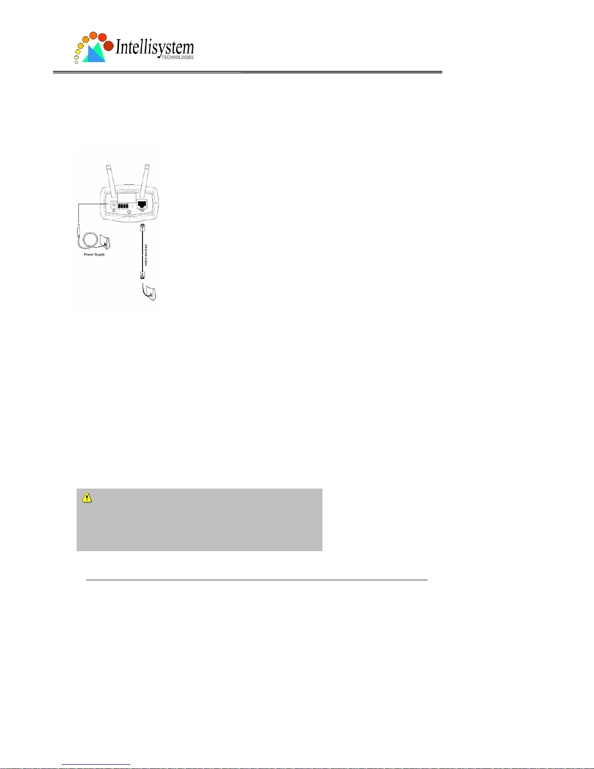
Hardware installation
All necessary accessories
can be found in the
product package except
for the Ethernet cable that
depends on the user’s
environment. The
Ethernet cable should
meet UTP category 5 tha t
cannot exceed 100
meters.
Connect the jack of the power adapter to MiniAVServer
prior to plugging the utility end into the utility power socket. It
will reduce accidental electric surge shock.
Page 9

Intellisystem Technologies - http://www.intellisystem.it
As soon as the power adapter is plugged into the utility socket, the front L ED will switch between
green and red for several times. After passing the self-test, the LED will shut off and the IT150W
Network Camera will standby for software installation. Otherwise refer to Appendix A for
troubleshooting.
To install in Ethernet,
Make sure the Ethernet is firmly connected to a switch hub. After attaching the Ethernet cable plug in
the power adapter. If the LED turns out to be steady green after self-test, go to next paragraph
“Software installation”. If the Ethernet is not available, the IT150W Network Camera will switch to
wireless LAN mode.
To install in wireless LAN,
If the Ethernet is not available while power on,the IT150W Network Camera will search for an y access
point with the SSID “default”. Once any access point is found, the LED will turn green to wait for
installation. If the network environmen t cannot meet the default settings, install the I T150W Network
Camera in Ethernet to proceed with wireless LAN configuration.
The IT150W Network Camera will automatically detect and operate in the available network
interface with the priority of Ethernet than WLAN. Operating in either network mode, the LED will
flash every second as heartbeat to indicate alive.
The IT150W Network Camera provides a general I/O terminal block with one digital input and one
relay switch for device control. Pin 1 and pin 2 can be connected to an exter nal sensor and the sta te
of voltage will be monitored from the initial state 'LOW'. The relay switch of pin 3 and pin 4 ca n be
used to turn on or off the external device.
Consult with the dealer of the peripherals for correct installation.
Page 10

Intellisystem Technologies - http://www.intellisystem.it
1 DI- INPUT (Initial state of DI is low)
2 DI+ INPUT (Max. 50mA, 12VDC)
3 SW_COMMON OUTPUT (open from SW_OPEN at initial state)
(close with SW_OPEN when set DO to ON)
4 SW_NOPEN OUTPUT (Max. 1A, 24VDC or 0.5A, 125VAC)
Page 11
IT150W User’s Manual
Intellisystem Technologies - http://www.intellisystem.it
8
Software installation
In the following content, "user" refers to those who can access the IT150W Network Camera
and "administrator" refers to the supervisor who can configure the IT150W Network Camera
and grant users access.
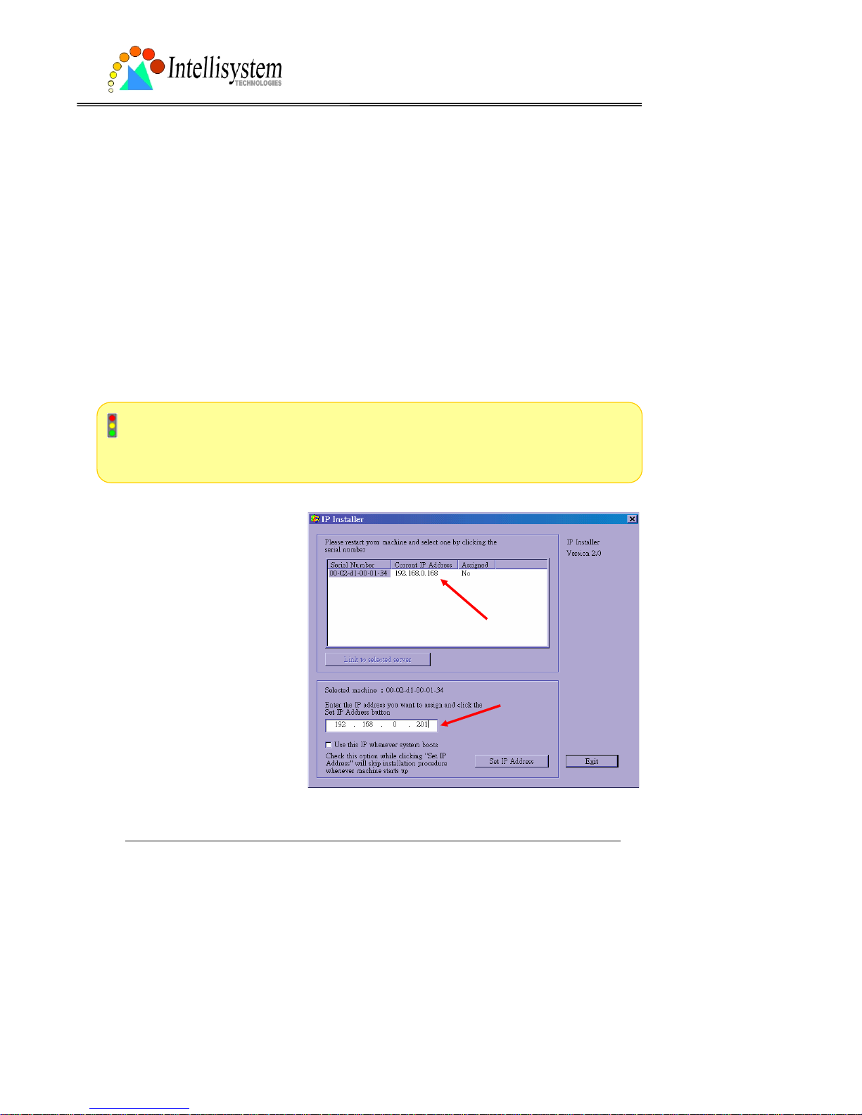
When completing the hardware installation, administrators need to run the Installer program
included in the product CDROM to locate the newly installed IT150W Network Camera. Any
IT150W Network Camera standby for software installation will be captured by the Installer
program. Therefore there may be several entries shown in the window. Administrators may
differentiate the IT150W Network Camera with the serial number and click on the entry with
"Assigned" field labeled "No" to perform software installation. The serial number is printed on
the labels on the carton and the rear panel of the IT150W Network Camera’s body.
To install the IT150W Network Camera for wirele ss usa ge, it is rec omme nded to ins tall in
Ethernet first. After successfully entering the network configuration page, input the correct
WLAN settings, remove the Ethernet cable and recycle the power to work in WLAN.
The IP address shown in " Cur re nt
IP Address" field depends on the
local network. It may get from the
DHCP server for the
administrator's reference. If ther e
is no DHCP server, administrators
can choose any neighbor IP
address of the PC. The Installer
program will check the IP address
automatically; there will be a
warning message if it conflicts
with others.
Page 12

IT150W User’s Manual
Intellisystem Technologies - http://www.intellisystem.it
9
If administrators want to use another IP address, modify the IP address text field. If the
administrator wants to fix the IP address of the unit, check the option "Use this IP whenever
system boots" to skip future installation procedures. Otherwise the unit will need installation
whenever it is restarted.
Click on “Set IP Address” button to
proceed.
Enter the wireless LAN settin gs accordin g to
the access point in infrastructure or Ad Hoc
master. The connection mode, SSID, WEP
settings are required. If th e setting s are not
sure at this stage, click “Skip” to continue
installation in Ethernet. All the settings can
be entered later from the web configur ati on
page.
Page 13
IT150W User’s Manual
Intellisystem Technologies - http://www.intellisystem.it
10
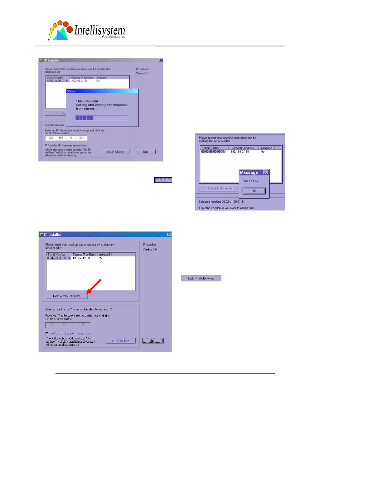
After clicking on “Save”, a progressive bar
will indicate the installatio n proc ess.
Congratulations! Now the IT150W Network Camera
is ready for access. After clicking on
in the
successful dialog, the "Assigned" field will be labeled "Yes".
Administrators should keep the address information for
users’ request.
If there is any error dialog rather than
“Set IP OK”, please follow the next page.
Administrators may click directly on
to access the newly
installed server in the default browser.
Page 14
IT150W User’s Manual
Intellisystem Technologies - http://www.intellisystem.it
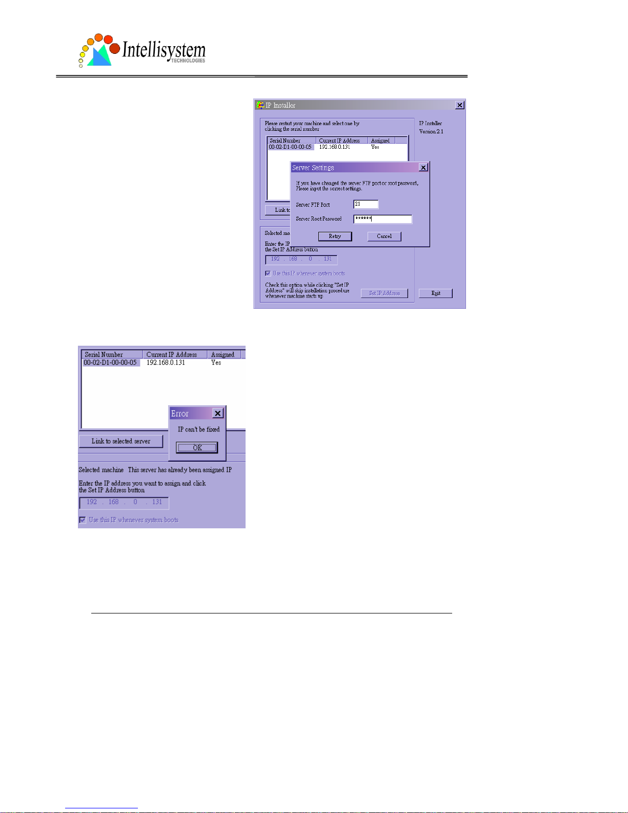
11
When administrators choose “Use this IP
whenever system boots” or fill any
wireless network settings, the local FTP
server port and root password of the
IT150W Network Camera will be utilize d.
If they have been changed prior to the
installation, a confirmation window will
pop out to request correct settings.
After entering the correct settings, press
“Retry”.
If the “Server FTP Port” or “Server Root Password”
is lost, click “Cancel” to exit. In this ca se, the IP
address of the IT150W Network Camera will still
be installed though it is not fixed for further reboot.
If the root password is correct, administrator can
log in to browse the cor rect local FTP server port in
the network settings. Otherwise refer to Appendix
A Troubleshooting to restore factory default
settings and then u se the i nstaller to in stall ag ain.
Once installation is complete, administrators should proceed to the next section
"First access to the IT150W Network Camera" for necessary checks and
configurations.
Page 15

IT150W User’s Manual
Intellisystem Technologies - http://www.intellisystem.it
12
First access to the IT150W Network Camera
Check network settings even if connected already
Although the IT150W Network Camera already can be connected after software installation
from Local Area Network, administrators should complete the network settings in the
configuration page including the correct subnet mask and IP address of gateway and DNS. Ask
for the network administrator or Internet service provider for the detail informati on. By default
the IT150W Network Camera will need administrator's installation e very time i t reboots. I f the
network settings are sure to work all the time, disable the install option. Refer to “Network
settings” in system configuration page for details. Once any setting is entered incorrectly and
thus hangs the IT150W Network Camera, restore the factory settings according to the steps in
troubleshooting.
Add password to protect from offense from strangers
Since the administrator’s password is blank by default, the IT150W Network Camera will not
ask for any password. However the administrator should change the password as soon as
possible to protect from network intruders. Once the administrator’s password is saved, the
IT150W Network Camera always needs user name and password before access. The
administrator can setup at most twenty user accounts. Each user is able to access the IT150W
Network Camera except for system configuration. Some critical func tions are lim ited only for
administrators such as system configuration, user administration and software upgrade. The
user name of the administrator is assigned to “root” permanently. Once the password is
changed, the browser will display an authentication window to ask for the new password. There
is no way to discover administrator’s password. If the password is forgotten, only restoring
factory defaults can help.
Page 16
IT150W User’s Manual
Intellisystem Technologies - http://www.intellisystem.it
13
How to Use
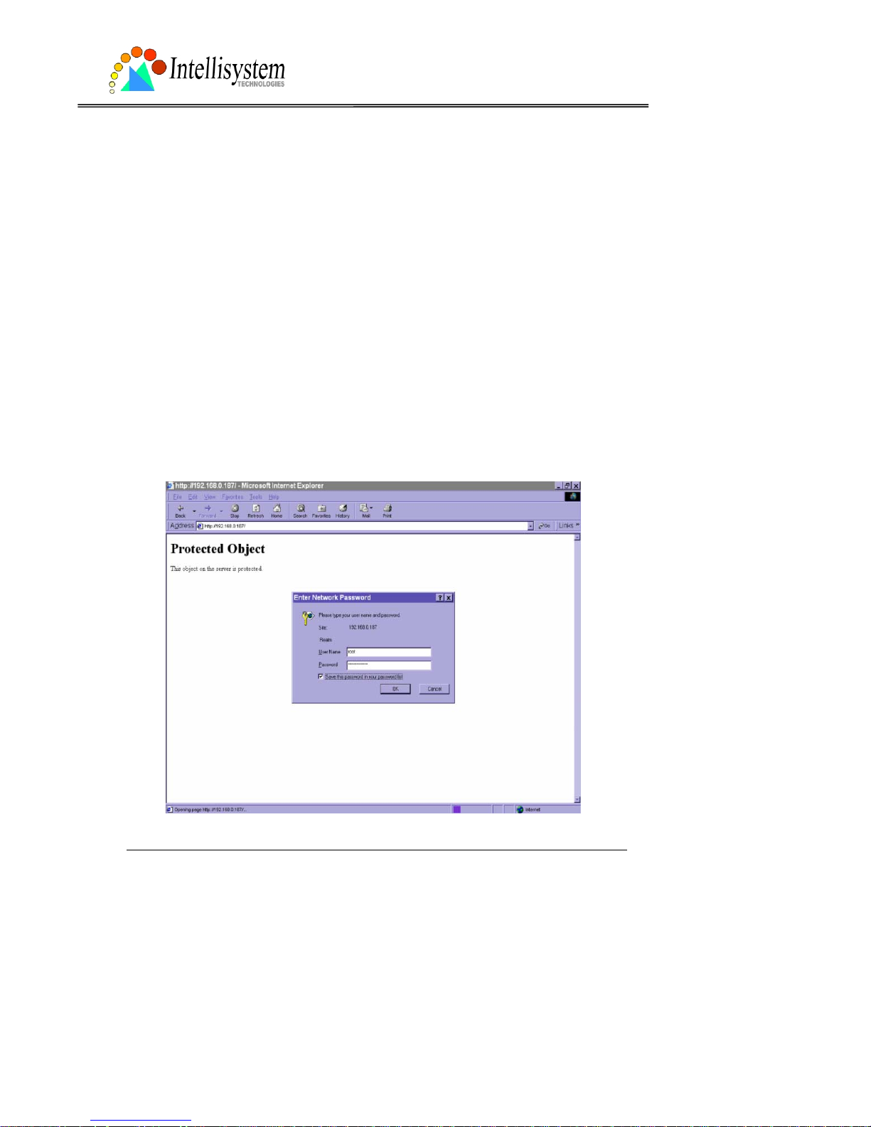
Authentication
After opening the Web browser and typing in the URL of the IT150W Network Camera, a
dialogue window may pop up to request a username and password except that the
administrator does not save any password. Upon successful authentication, the main page will
display like the figure below.
In the figure, the foreground is the login window and the background shows the message when
authentication fails. The user may check the option to save the password for future
convenience.
Page 17
IT150W User’s Manual
Intellisystem Technologies - http://www.intellisystem.it
14
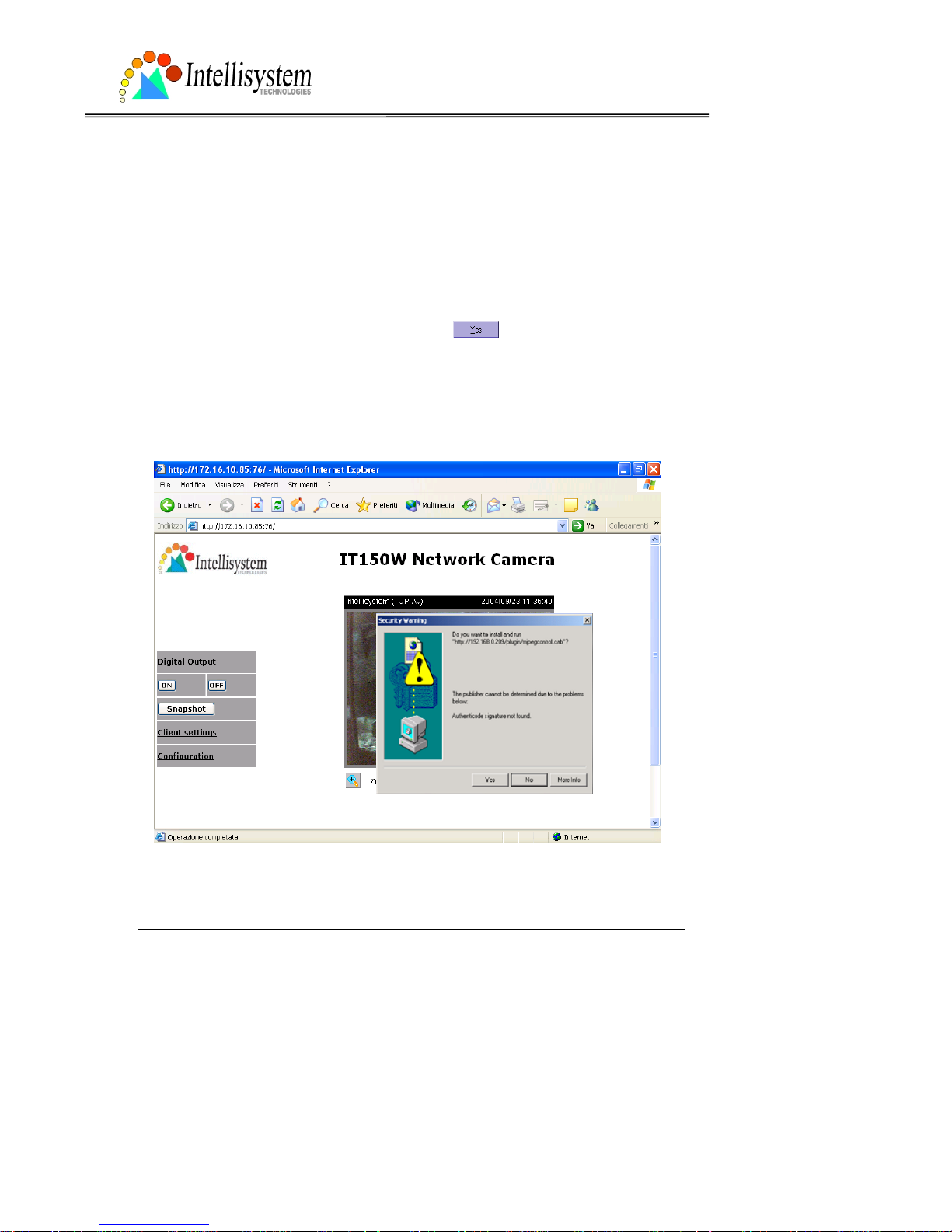
Installing plug-in
If it is initial access to the IT150W Network Camera in Windows, the web browser may prompt
for permission to install a new plug-in that is provided by the IT150W Network Camera. Prompt
or not and the prompt message depend on the Internet security settings of user’s PC or
notebook. The highest security level may prohibit any installation and execution attempt even
the plug-in is safe. This plug-in has been registered for certificate and is used to display the
motioned pictures in the browser. Users may click on
to proceed. If the web browser
does not allow the user to install, check the Internet security option to lower secu rity levels or
contact network supervisors.
Page 18
IT150W User’s Manual
Intellisystem Technologies - http://www.intellisystem.it
15
Primary user’s capability
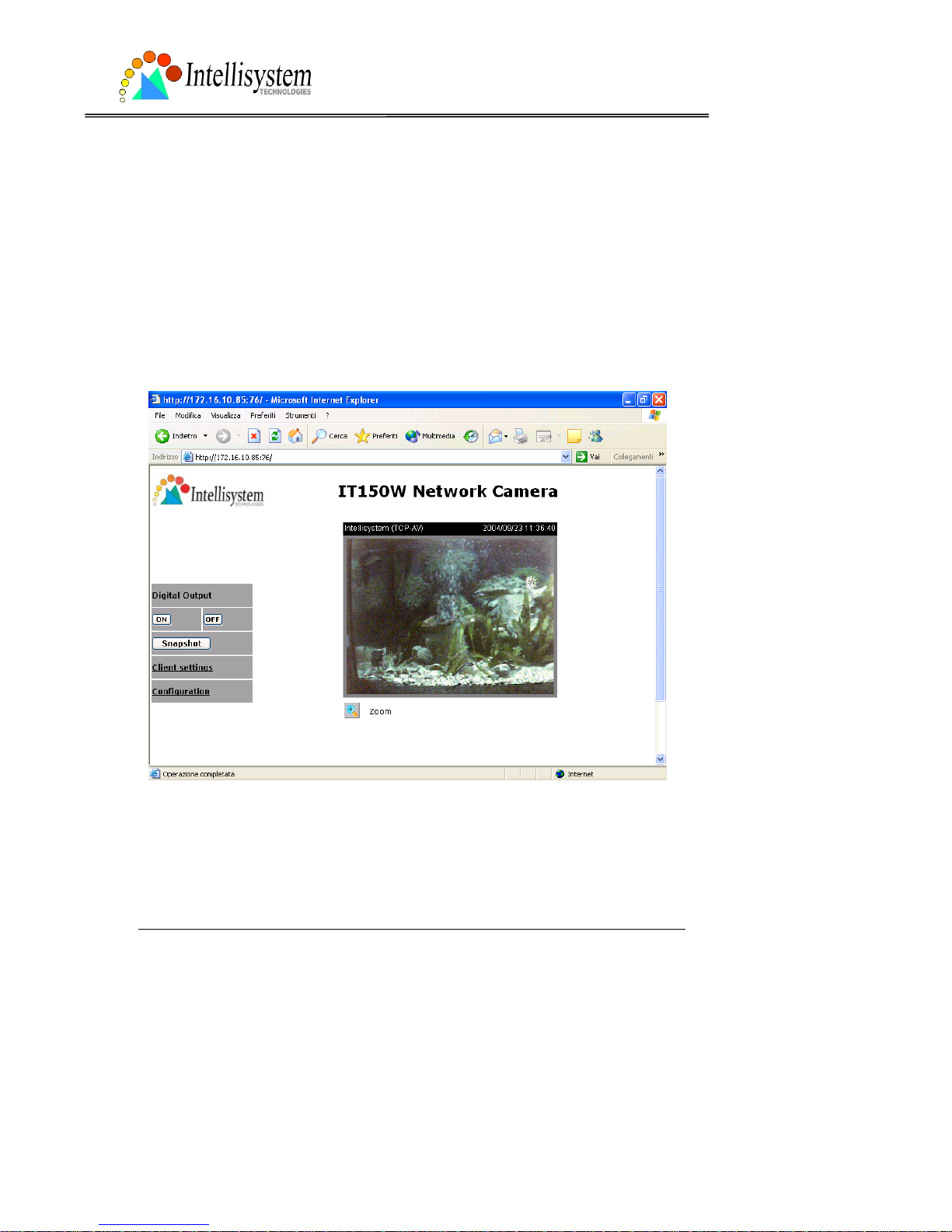
Main screen with camera view
There is a logo image shown in the upper left corner . It can link to other web sites or resources
depending on the settings in c onfiguration. The assigned captio n and system date/time wi ll
display in the banner abo ve the image wind ow. Th ere might be some wind ows enclosed by red
lines shown in the image as soon as mot ion is detect ed in the related windows. C lick on the
configuration link to the right of the image window to enter the configuration page.
Page 19

IT150W User’s Manual
Intellisystem Technologies - http://www.intellisystem.it
16
Connection type
If it is the first access to “Connection type” page in Windows, the web browser will ask to install
a new plug-in that is provided by the IT150W Network Camera. This plug-in has been
registered for certificate and is used to change the parameters at the client side. Users may
click on
to install the plug-in. If the web browser does not allow the user to install,
check the Internet security to lower the security level or contact network supervisors.
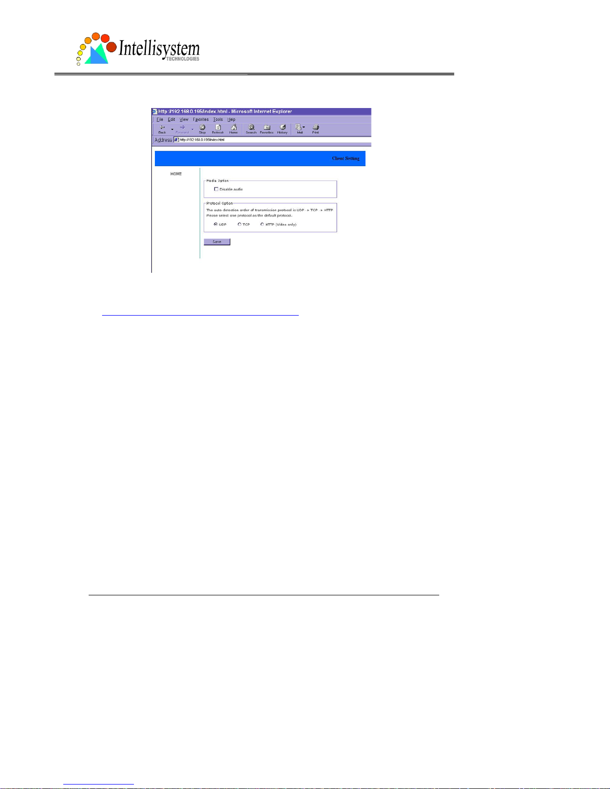
There are two settings for the client side. One is “Medi a Option” fo r users to de termine if t he
audio should be muted. The other is “Protocol Option” to choose the connection protocol
between client and server. There are three protocols to optimize your usage - UDP, TCP and
HTTP. With UDP protocol, audio and video streams ca n be mo re rea l-time . But some packets
may be lost due to network burst traffic and images will be obscure. If TCP protocol is selected,
packet loss would not occur and video display will more accurate. But the real -time effect is
worse than UDP protocol. If th e networ k is protected by a firew all and it o pens HT TP p ort (80)
only , HT TP protoc ol must be selected. I n this m ode, audi o will not be sent an d you c an see the
video only. If you have no special needs and no idea to choose one among them, simply choose
UDP. Generally the client will automatically try these protocols by the following order, UDP →
TCP → HTTP. After the client connects to the IT150W Network Camera successfully, “Protocol
Option” will show the working protocol. The chosen protocol will be recorded in the user's PC
and used for next connection. If the network environment is changed or users want to let web
browser detect again, select UDP manually to save and then return HOME to connect again.
Page 20
IT150W User’s Manual
Intellisystem Technologies - http://www.intellisystem.it
17
<url> http://<IT150W Network Camera>/protocol.html
<IT150W> is the domain n ame or original IP address of the IT15 0W Network Camera.
Page 21
IT150W User’s Manual
Intellisystem Technologies - http://www.intellisystem.it
18
Administrator’s capability
Tune the best performance
The best performance means the image refresh rate should be the fastest as possible and the
video quality should be the best as possible at the lowest network bandwidth as possible. Three
factors, “Maximum frame rate”, “Fix bit rate”, and “Fix quality” in the Video configura tion page,
are correlative to the performance.
My priority is real-time motioned images
To achieve the real-time visual effect, the network bandwidth should be large enough to
transmit 20 image fr ame s or more. I f you are in th e broadb and networ k over 1 Mbps, you can
fix the bit rate to 1000Kbps or 1200Kbps, or fix t he quality to ac hieve the maximum frames.
The maximum frame rate is 25 in 50Hz system and 30 in 60Hz system. If your network
bandwidth is more than 384Kbps, you can fix the bit rate according to your bandwidth and set
the maximum frame rate to 25 or 30. If the images vary dramatically in your environment, you
may slow down the maximum frame rate to 20 to decrease the transmitted data for better
video quality since human could not e asily te ll the d iffer ence betw een 20 and 25 or 30 fr a mes
per second. If your network bandwidth is below 384 Kbps, you should fix the bit rate according
to your bandwidth and try out the best performa nce by tuning the maximum frame rate. The
larger frame rat e in slow network will blur th e images. Y ou may also tr y to choose “Half” in size
option for better image s or “Hal fx2” for larger im age siz e. Note that even you ha ve well tuned
Page 22

IT150W User’s Manual
Intellisystem Technologies - http://www.intellisystem.it
19
the parameters, the performance may still vary from perso n to person when multiple users
view at the same time. Because the network has burst constraint and everyone’s environment
is not the same, any poor connection will drop the normal per formance.
My priority is clear identification for each image
To have the best video qualit y, you should fix the quality to det ailed or ex ce ll ent and t un e th e
maximum frame rate to suit for your netwo rk bandwidth. If you get some broken pictures in
slow network, you can choose TCP protocol in “Connection type” for more accurate
transmission but the received images may have certain time delay. Note that any slow
connection in multiple users wil l drop the proper performance.
I want to compromise between real-time and clear images
If you have a broadband network, choose fix quality to normal or better rather than fix
bandwidth. Otherw ise fix the ba ndwidth a ccording to your actual netwo rk speed and s et the
frame rate to 30. If the images look bad, select the lower frame rate above 15. If the images
are not improved, select the lower bandwidth.
Page 23

IT150W User’s Manual
Intellisystem Technologies - http://www.intellisystem.it
20
Open accounts for users
Protect the IT150W Network Camera by passwords
The IT150W Network Camera is shipped without any password by default. That means
everyone can access the IT150W Network Camera including the configuration as long as the IP
address is known. It is necessary to assign a password if the IT150W Network Camera is
intended to be accessed by others. Type a new word twice in ○,
1
to enable protection. This
password is used to identify the administrator. Then add an account with user name and
password for your friends in ○,
2
. The IT150W Network Camera can provide twenty accounts
for your valu able customer s or friend s. Each acco unt identifi es the acce ss right r ather than th e
real visitor. That allows multiple visitor s sh are th e sam e account of different level. An option
to access DI/DO is provided for each account. Some users may need to prohibit from
controlling your attached de vices. You may delet e so me users from ○,
3
.
More flexible options for viewers
○
,4
The first option allows anyone uses “demo” as the user name to view without password.
Administrators can also decide if more viewers are allowed to watch the video if the viewers
exceed the limit. The overloaded viewers will have snapshot mod e instead.
Page 24

IT150W User’s Manual
Intellisystem Technologies - http://www.intellisystem.it
21
Change homepage layout
How to change the subject text of homepage
1. Click on “Configuration” on homepage,
2. Change the text in “Host nam e”,
3. Click on “Save” button.
Page 25

IT150W User’s Manual
Intellisystem Technologies - http://www.intellisystem.it
22
How to change the font color
1. Click on “Configuration” on homepage,
2. Click on “Homepage layout” at the left column,
3. Find “Font color” and pull down the list to choose any color you like,
4. Click on “Save” button.
* The font color is better to contrast with the background.
How to change the background
1. Click on “Configuration” on homepage,
2. Click on “Homepage layout” at the left column,
If you want to display simple color without any image,
3. Find “Background gr aph” and choose “blank”,
4. Find “Background color” and pull down the lis t to choose any color you like,
5. Click on “Save” button.
* The background color is better to contrast with the font.
If you want to use the image from another web site as background,
3. Find “Background graph” and choose “Url”,
Page 26

IT150W User’s Manual
Intellisystem Technologies - http://www.intellisystem.it
23
4. Type the URL of the image on the Internet in the edit box, for example,
“http://www.intellisystem.it/img/logo.gif”,
5. Click on “Save” button.
If you want to change the default background image stored in the IT150W Network Camera,
3. Find “Background graph” and choose “default”,
4. Click on “Save” button,
5. Prepare an image file with size less than 131000 bytes and rename it to wallppr.jpg,
6. Open an FTP client program and connect to the IT150W Network Camera . The user name
and password is as same as the administrator’s.
7. Transfer wallppr.jpg in local folder to the IT150W Network Ca me ra,
8. Close the FTP program and reload the homepage of the IT150W Network Camera.
Page 27

IT150W User’s Manual
Intellisystem Technologies - http://www.intellisystem.it
24
How to change the image logo at the upper left corner of homepage
1. Click on “Configuration” on homepage,
2. Click on “Homepage layout” at the left column,
If you want to remove any logo,
3. Find “Logo graph” an d choose “blank”,
4. Click on “Save” button.
If you want to use the image from another web site as logo,
3. Find “Logo graph” and choose “Url”,
4. Type the URL of the image on the Internet in the edit box, for example,
“http://www.intellisystem.it/img/logo.gif”,
5. Click on “Save” button.
If you want to change the default logo stored in the IT150W Network Camera,
3. Find “Logo graph” and choose “default”,
4. Click on “Save” button,
5. Prepare an image file with size less than 65000 bytes and rename it to logo.gif,
6. Open an FTP client program and connect to the IT150W Network Camera. The user name
and password is as same as the administrator’s.
7. Transfer logo.gif in local folder to the IT150W Network Camera,
8. Close the FTP program and reload the homepage of the IT150W Network Camera.
If you want to add hyperlink to the logo image,
3. Find “Logo link” and type the hyperlink in the edit box, for example,
http://www.intellisystem.it,
4. Click on “Save” button.
Page 28

IT150W User’s Manual
Intellisystem Technologies - http://www.intellisystem.it
25
How to design my own homepage to replace the current one
1. Prepare your own homepage with size less than 65000 bytes and rename it to user.htm,
2. Insert the html codes of video ob ject, the bold Italian text in the following example, into the
appropriate position in user .htm. N ote that the codes of vid eo object must be copied exactly the
same including the letter case.
****** Intellisystem Technologies - Example homepage begin ******
<html>
<head>
<title>Example – custom homepage</title>
</head>
<body background="/pic/wallppr.jpg">
<p>
<a href="/setup/config.html">
<img src="http://www.intellisystem.it/img/logo.gif" align="left" width="100"
height="29">
</a>
<font size="7" face="Comic Sans MS" color="#FF0000">
IT 150W Demo Page
</font>
</p>
<p align="left">
<!-- Copy the next bold line to where you want to show the image coming from IT150W.
This line is remark only and is hidden on homepage. //-->
<OBJECT ID=VAMCtrl></OBJECT>
</p>
</body>
</html>
****** Example homepage end ******
Page 29

IT150W User’s Manual
Intellisystem Technologies - http://www.intellisystem.it
26
3. Open an FTP client program and connect to the IT150W Network Camera. The user name
and password is as same as the administrator’s.
4. T ransfer user.htm in local folder to the IT150W Network Camera,
5. Close the FTP program and reload the homepage of the IT150W Network Camera,
6. Click on “Configuration” on homepage,
7. Click on “Homepage layout” at the left column,
8. Check “Use the customized homepage”.
9. Click on “Save” button and return to homepage.
* The user.htm only provides plain t ext cont ent that script s and URL of extern al resou rces can
be used to adorn the homepage. Refer to tutorials of writing HTML and scripts.
If the customized homepage goes wrong and cannot display, link to the “Homepage layout”
page, “http://<IP address of IT150W Network Camera>/setup/layout.html”, to disable “Use
the customized homep age” .
Page 30
IT150W User’s Manual
Intellisystem Technologies - http://www.intellisystem.it
27
Build a multimedia web attraction site
Show off to my friends – mid-scale service
The IT150W Network Camera can allow ten visitors on-line simultaneously. Just follow the
installation, focus the IT150W Network Camer a on any view you w ould like friends to shar e and
tell them the address to type in the web browser . Of course you h ave to maintain your friend list
in the security confi guratio n pa ge to filte r un expec te d stranger s. No nee d to have the geeks ’
skill and equipments, no need to find suitable software.
Show my products or scenic spot for e-business – large-scale service
If the visitors may exceed the account limit,the IT150W Network Camera can supply extra
viewers the homepage of snapshot mode that will have the JPEG still image refreshed
periodically and automatically. It needs script function supported by the web browser.
1. Click on “Configuration” on homepage,
2. Click on “Security” at the left column,
3. Go to the page bottom and check “Allow more viewers with snapshot mode”,
4. Set the snapshot interval to refresh the still image automatically. The longer the snapshot
interval is, the better the snapshot mode works for more viewers.
Page 31
IT150W User’s Manual
Intellisystem Technologies - http://www.intellisystem.it
28
If you want to expand the viewe rs tremendous ly, host a powerful web site that can handle s
large network traffic and attract eyeballs with the picture refreshed often by the IT150W
Network Camera.
If the web space has FTP service,
Setup the IT150W Network Cam era as an F T P cl ie nt to uplo a d the pict ures. The advantage is
the access of the IT150W Network Camera i s independent of the vi ewers to ensure the qu ality.
1. Click on “Configuration” on homepage,
2. Click on “Network” at the left column,
3. Fill the FTP related settings including server , user name and password, as well as the upload
path if specified by the web spac e,
4. Click on save and wait for system restart,
5. Click on “Application” at the left column,
6. Select the weekday and daily schedule you want to upload the pictures,
7. Select “Sequential operation” and set the interval,
8. Select FTP without date time suffix as the upload method and click on save,
9. The image file uploaded to the web space is named “video.jpg”. Check if the file is
successfully uploaded to the correct folder,
Page 32

IT150W User’s Manual
Intellisystem Technologies - http://www.intellisystem.it
29
10. Prepare a homepage with the embedded image reference to the image file uploaded via FTP
in advance.
If the web space has no FTP service,
An auto-refresh homepage can be used to periodically poll the newest image from the IT150W
Network Camera. It is mostly useful in the free web space provider as their FTP service may be
limited to use.
1. Prepare an auto-refresh homepage like the following example. The URL of image is
http://“IP address of the IT150W Network Camera”/cgi-bin/video.jpg. Modify the IP address
according to your IT150W Network Camera. Also define the refresh interval according to your
network bandwidth for best effect. Too frequent refresh rate for a grea t deal of visitors may
overload the IT150 Network Camera W and retard the response.
Page 33

IT150W User’s Manual
Intellisystem Technologies - http://www.intellisystem.it
30
****** Intellisystem Technologies - Example homepage begin ******
<html>
<head>
<title>Example - auto refresh</title>
</head>
<body background="/pic/wallppr.jpg">
<p align=left>
<font size="7" face="Comic Sans MS" color="#FF0000">
IT150W Demo
</font>
</p>
<p align=left>
<!-- Begin of scripts to auto refresh the ima ge. Change the IP add ress in the image UR L and
refreshrate if necessary. //-->
<script language=javascript>
var image="http://217.133.4.176:76/cgi-bin/video.jpg"; //IMAGE URL
var refreshrate=5; //SECONDS BETWEEN REFRESH
var imgwidth=352; //IMAGE WIDTH
var imgheight=240; //IMAGE HEIGHT
function refresh(){
document.images["pic"].src=image+"?"+new Date();
setTimeout('refresh()', refreshrate*1000);}
document.write('<img src="'+image+'" height="'+imgheight+'" width="'+imgwidth+'"
name="pic">');
if(document.images)window.onload=refresh;
</script>
<!-- End of scripts to auto refresh the image. //-->
</p>
</body>
</html>****** Example homepage end ******
Page 34

IT150W User’s Manual
Intellisystem Technologies - http://www.intellisystem.it
31
Build a security application
Administrators can combine options on the application page to perform many useful security
applications. There are two trigger
sources coming from attached devices
and/or motion detection. There are
also two kinds of actions responding
to events including uploading
snapshots over internet and driving
attached devices. To upload the
snapshots, users can choose wither
email or FTP according to user’s needs.
Both e-mail and FTP use the network
settings on the network page. Refer to
the definition section for detail
configuration.
1. Click on “Configuration” on
homepage,
2. Click on “Application” at the left
column,
3. Check the weekdays as you need
and give the period of "Snapshots
begin" time and "Snapshots end" time
to monitor the trigger conditions
every day,
4. Check the “Event operation”. The
trigger condition can be set to
detected motion or status of the
attached device,
5. Set the delay before detecting next event to avoid continuous false alarms following the
original event,
6. Set the delay to take snapshots after event to capture the direction of the moving objects,
Page 35

IT150W User’s Manual
Intellisystem Technologies - http://www.intellisystem.it
32
Send snapshots when motion is detected
If no external sensor is available, administrators ca n utilize the built-in motion detection to
monitor any abnormal movement and then send emails with snapshots included for security
check.
7. Click on “Motion detection” at the left column,
8. Check “Enable motion detection”,
9. Click on new to have a new window to monitor video,
10. Type in a name to identify,
11. Use mouse to drag the window corner to resi ze or the title bar to move,
12. Tune the “Sensitivity” and “Percentage” according to the local environment. The higher
sensitivity, the easier motion is detected. The higher percentage, the more difficult to detect
small moving objects,
13. Click on save will enable the activity display. Green means the motion in the window is
under the watermark se t by administrators and red means it is over the watermark,
14. Click on “Application” at the left column,
15. Check the window name set in step 10,
16. Check “Upload snap shots while motion detected”,
If emails with snapshots are preferred,
17. Check “Send snapshots by email”,
18. Click on save to validate.
Page 36

IT150W User’s Manual
Intellisystem Technologies - http://www.intellisystem.it
33
Software revision upgrade
Customers can obtain the up-to-date software from our web site. An easy-to-use Upgrade
Wizard is provided to upgrade the IT150W Network Camera with some clicks. This function is
open to administ rators only. To upgrade the system, follow the procedures below.
1. Download the firmware file named FLASH.BIN from th e appropriate product folder.
2. Run the Upgrade Wizard and proceed by the prompts. Refer to the instructions of Upgrade
Wizard for details.
3. The whole process will finish in couple minutes and automatically restart the system.
If the power fails during the writing process of Flash memory , the program in t he memory
of IT150W Network Camera may be destroyed permanently. If IT150W Network Camera
cannot restart properly, ask the dealer for technical service.
Page 37

IT150W User’s Manual
Intellisystem Technologies - http://www.intellisystem.it
34
Definition of Configuration
System configuration can be accessed only by administrators. Each category in the left column
will be explained in the following pages. The bold texts are those specific phrase on the option
pages. Administrators may type the URL below the figure to directly enter the frame page of
configuration. If administrators also want to set certain options through the URL, read the
reference appendix for details.
<url> http://<IT150W Network Camera>/setup/config.html
<IT150W> is the domai n name or original IP address of the IT150W Network Camera.
Page 38

IT150W User’s Manual
Intellisystem Technologies - http://www.intellisystem.it
35
System parameters
"Host name", the text will display as title at the top of the main page.
“T urn off the LED indicator”, check this option to shut off th e LED beside the lens. It can prevent
others from observing the operation.
"Keep current date an d time", click to reserve the current date and time of the IT150W Network
Camera. An internal real-time clock maintains the date and time even when the power of the
system is turned off.
"Sync with comput er time", synchronize the d ate and time of the IT150W Ne twork Camera with
the local computer. The read-only date and time of PC is displayed as updated.
“Manual”, adjust the date and time according to what entered by administrators. Notice the
format in the related field while typing.
“Automatic”, syn chronize with the NTP serv er over the Internet whenev er the IT150W Network
Camera starts up. It will fail if the assigned timeserver cannot be reached.
“NTP server”, assign the IP address or domain name of the timeserver. Leaving the text box
blank will let the IT150W Network Camera connect to default timeservers.
"Time zone", is used to adjust the hour get from timeservers for local settings.
Remember to click on
to validate changes. The later click on , the less accurate time
set by manual.
Page 39

IT150W User’s Manual
Intellisystem Technologies - http://www.intellisystem.it
36
User group administration
“Root password”, t o chan ge the admin istr ator’s password, type the new passw ord in both text
boxes identically. What is typed will be displayed as asterisks for the s ecurity purpose. A fter
pressing
, the web browser will ask administrators for the new password for access.
“Add user”, type the new user's name and password and press
to insert the new entry.
The new user will display in the user name list for deletion. There are maximum twenty user
accounts. Each user can have privilege to “Permit to access DI/DO”.
“Delete user”, pull down the user list to find the user nam e and press
.
“Allow ‘demo’ account to view”, click to permit who typing “demo” as user name while
authentication. No password is needed for demo account. Note that demo account is restricted
to view only.
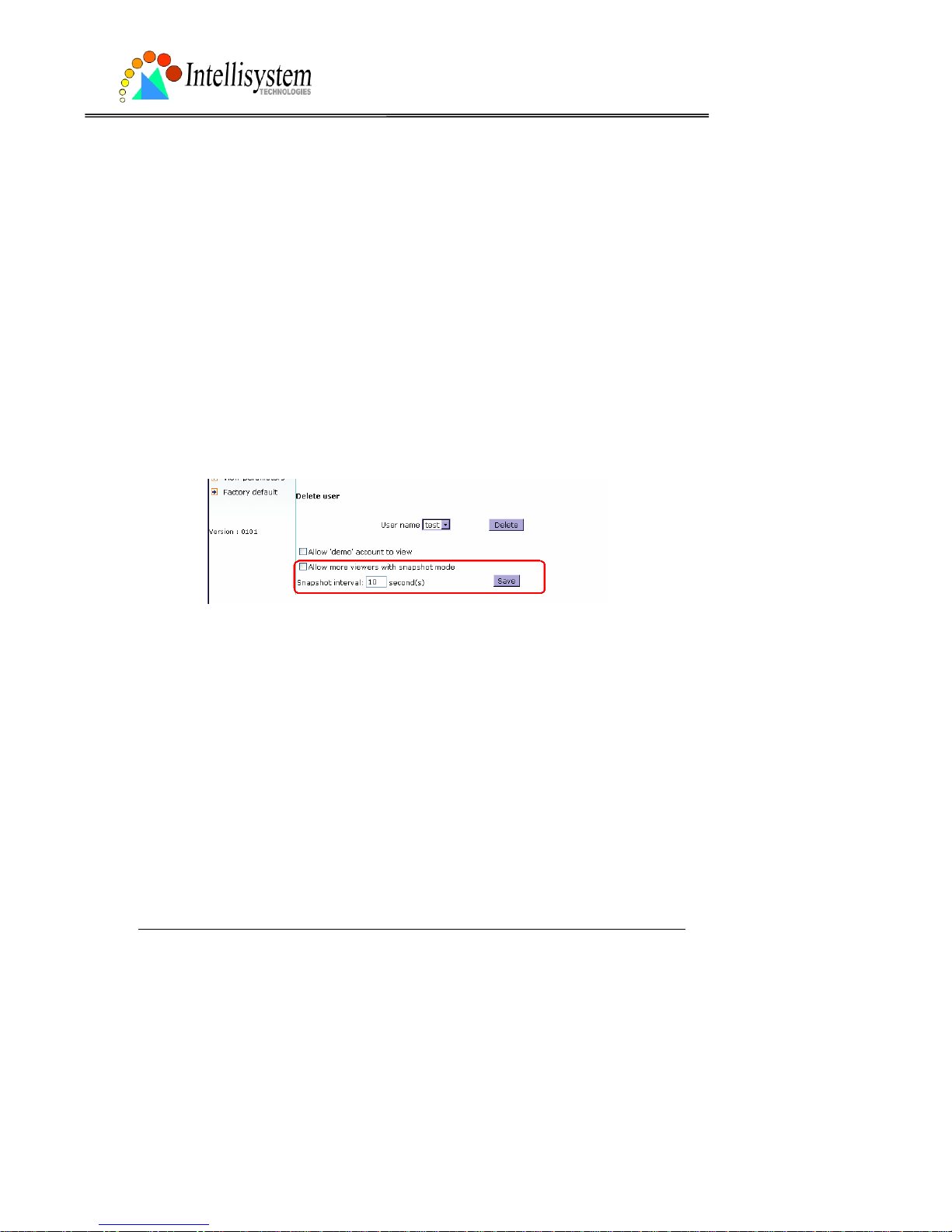
“Allow mor e view ers wit h snapsh ot m ode” can let m ore view ers th an limit ed ac coun t to w atch
the video. However the video is a still image automatically refreshed by the interval defined
below. This feature must be supported by java script capab ility of web browsers.
“Snapshot interval” defines the refresh rate of the still image in the homepage seen by
overloaded viewers.
Page 40

IT150W User’s Manual
Intellisystem Technologies - http://www.intellisystem.it
37
Network settings
Any change made to this page will make the system restart to validate. Make sure every field
is correctly typed before clicking on
.
"Reset IP address at next boot", the default status is checked to eliminate incautious mistakes
during installation. However it is very annoying to perform sof tware installation whenever the
IT150W Network Camera starts. Once the network settings, especially the IP address, are
correct, uncheck this option to use permanently. This option can also be disabled using the
Installer program. Once the option is disabled, the IT150W Network Camera will skip
installation at the next boot and t he Installer program will no longer find the installed units.
That implies that the IT150W Network Camera cannot be accessed if no one remember s the IP
address, except by restoring factory default settings. However, with this option disabled the
IT150W Network Camera can automatically operate normally after restarting in case of losing
power.
General
“IP address”, it is necessary for network identification.
“Subnet mask”, it is used to determine if the destination is in the same subnet. The default
value is “255.255.255.0”.
“Default router”, it is the gateway used to forward frames to destinations in different subnet.
Invalid router setting will fail in transmission to destinati ons in different subnet.
“Primary DNS”, primary domain name server who translates names to IP addresses.
“Secondary DNS”, secondary domain name server to backup the primary one.
HTTP
“Http port”, it can be other than defa ult port 80. Once the port is changed, users must be
informed for successful connection. For instance, when the administrator changes the HTTP
port of the IT150W Network Camera whose IP address is 192.168.0.100 from 80 to 8080, users
must type in the web browser “http://192.168.0.100:8080” instead of “http://192.168.0.100”.
Page 41

IT150W User’s Manual
Intellisystem Technologies - http://www.intellisystem.it
38
Streaming
“Control channel port”, it can be other than default port 5001 to cooperate with the port opened
by the firewall.
“Audio channel port”, it can be other than default port 5002 to cooperate with the port opened
by the firewall.
“Video channel port”, it can be other than default port 5003 to cooperate with the port opened
by the firewall.
“Improve audio quality in lo w ban d width environment”, if the IT150W Network Camer a w or ks
in versatile or low network bandwidth environment, users can check this option to improving
audio quality by sacrificing some real-time synchronization.
WLAN Configuration
“SSID” (Service Set Identifier), it is a name that identifies a wireless netwo rk. Access Points
and wireless clients attempting to connec t to a specific WLAN ( Wireless Local Area Ne twork)
must use the same SSID. The default setting is default. Note: The maximum length of SSID is
32 single-byte characters and SSID can’t be any o f “, <, > and space character.
“Wireless mode”, cli cking on the pull-down menu to select from the following options:
“Infrastructure” – connecting the WLAN via an Access Point. (The default setting)
“Ad-Hoc” – connecting directly to a host equipped with a wireless adapter in a peer-to-peer
environment.
“Channel”, while in infrastr ucture mode, the channel is selecte d automatically to match the
channel setting for the selected Access Point. In Ad-Hoc mode, the channel must be manually
set to the same channel for each wirel ess adapter. The default channel sett ing depends on th e
installed region.
“TX rate”, to select the maximum transmission rate on the network. 22Mbps is the default
setting.
“Preamble”, either “Long preamble” or “Short preamble” defines the length of the CRC block
(Cyclic Redundancy Check is a common technique for detecting data transmission errors) for
communication between the Access Point and the roaming wi reles s dev ice. Long Pream ble is
the default setting. Note: High network traffic areas should use the shorter preamble type.
“Data encryption”, checking the box to enable the data encryption. By default it is disabled.
“Auth. Mode”, choosing one of the following modes, (Auto is the defa ult setting)
“Auto” – Will automatically decide the authentication mode of the wireless client.
Page 42

IT150W User’s Manual
Intellisystem Technologies - http://www.intellisystem.it
39
“Shared” – allows communication only with other devices with identical WEP settings.
“Open” – communicates the key across the network.
“Key length”, selecting the key length among 64, 128 or 256 bits. 64bits is the default setting.
“Key format”, including hexadecimal or ASCII. “HEX” is the default setting.
“HEX” digits consist of the numbers 0~9 and the letters A-F.
“ASCII” is a code for representing English letters as numbers from 0-127 except “, <, > and
space characters that are reserved.
“Network Key”, entering a key in either hexadecimal or AS CII format. When selecting differ ent
key length, acceptable input length is listed as following:
64 bits key length: 10 Hex digits or 5 characters.
128 bites key length: 26 Hex digits or 13 characters.
256 bits key length: 58 Hex digits or 29 characters.
Note: When 22(“), 3C(<) or 3E(>) are inpu t in network key, the key format can’t be changed
to ASCII format.
Mail & FTP settings
SMTP
“SMTP(mail) server 1”, the domain name or IP addre ss of external email server.
“Recipient email address 1”, the email address o f re c ipients fo r s naps hots or log file. M ulti ple
recipients must be separated by semicolon, ‘; ’.
“SMTP(mail) server 2”, the domain name or IP address of another email server once the
previous server is unreachable.
“Recipient email address 2”, the email address of recipients for the backup server.
“Return email address”, The return email address once the mails fail to send out.
Some invalid settings may cause system failure to respond. Change the configuration only if
necessary and consult with network supervisor or experienced users for correct settings. Once the
system is lost contact, refer to Appendix A for reset and restore procedures.
Page 43

IT150W User’s Manual
Intellisystem Technologies - http://www.intellisystem.it
40
FTP
“Local FTP server port”, it can be other than default port 21. After changed, external FTP client
program must ch ange the server port of conn ection accordingly.
“1st FTP server”, the domain name or IP address of external FTP server. The following user
settings must be correctly configured for remote access.
“1st FTP user name”, granted user name on the external FTP server.
“1st FTP password”, granted password on the external FTP server.
“1st FTP remote folder”, granted folder on the extern al FTP server. The string must confor m to
the external FTP server. Some FTP server cannot accept preceding slash symbol before the path
if no virtual path mapping. Refer to the instructions of external FTP server for details. The folder
privilege must be open for upload.
“Primary FTP passive mode”, if the IT150W Network Camera is located inside the network
protected by firewall, data connection for FTP may be prohibited. Passive mode FTP can bypass
the rule and succeed to uplo ad snapshots. If the passi ve mode is selected, the IT15 0W Network
Camera can automatically attempt for active mode if the external FTP server does not support
passive mode.
“2nd FTP server”, the domain name or IP address of external FTP ser ver.
“2nd FTP user name”, granted user name on the backup FTP server.
“2nd FTP password”, granted password on the backup FTP server.
“2nd FTP remote folder”, granted folder on the backup FTP server.
“Secondary FTP passive mode”, passive mode setting for the backup FTP server.
Page 44

IT150W User’s Manual
Intellisystem Technologies - http://www.intellisystem.it
41
Video codec parameters
“Text on video”, the text will be displayed in the black bar above the video window with a
timestamp. The timestamp is captured from date and time of the IT150W Network Camera that
is maintained by a built-in real-time clock.
“Color”, select either one for color or monochrome video display.
"Size", there are three options for two video siz es. “H alf” has quarter siz e of “N ormal”. “H alf x
2” has the same video size as “Normal” but has worse quality. However it consumes less
network bandwidt h.
“Power line frequency (for fluorescent light)”, the fluorescent light will flash according to the
power line frequency that depends on local utility. Change the frequency setting to eliminate
uncomfortable flash image when the light source is only fluorescent light.
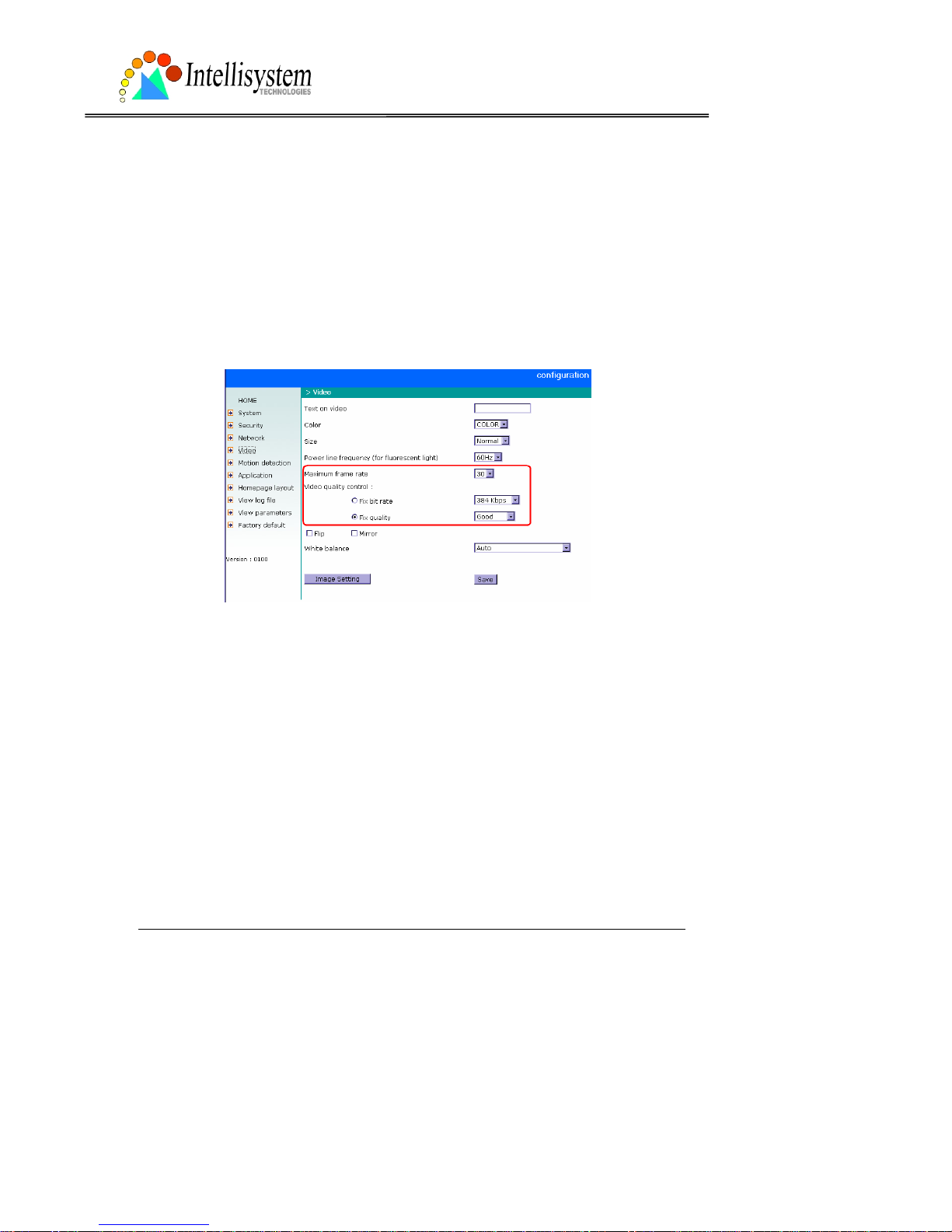
There are three dependent param eters provided for video performance adjustment. "Maximum
frame rate", it limits the maximal refresh frame rate that c an be combined with the "Video
quality control" to optimize the bandwidth utilization and video quality . If users want to fix the
bandwidth utilization regardless of the video quality, choose "Fix bit rate" and select the desired
bandwidth. The video quality may be poor in order to send maximal frames within the limited
bandwidth when images change drastically. Consequently to ensure the video detail
(quantization rate) regardless of the network, it will utilize more bandwidth to send the
maximal frames when images change drastically.
"Flip", vertically rotate the video.
"Mirror", horizontally rotate the video. Check both if the IT150W Network Camera is installed
upside down.
“White balance”, choose the suitable option for best color temperature.
, click this button to pop up another window to tune "Brightness", “Con trast”,
“Hue” and "Saturation" for video compensation. Each field has eleven levels ranged from -5 to
+5. The user may press
to fine-tune the image. When the image is O .K., press to
memorize the image settings.
can be clicked to recall the original settings without
changes.
Page 45

IT150W User’s Manual
Intellisystem Technologies - http://www.intellisystem.it
42
Page 46
IT150W User’s Manual
Intellisystem Technologies - http://www.intellisystem.it
43
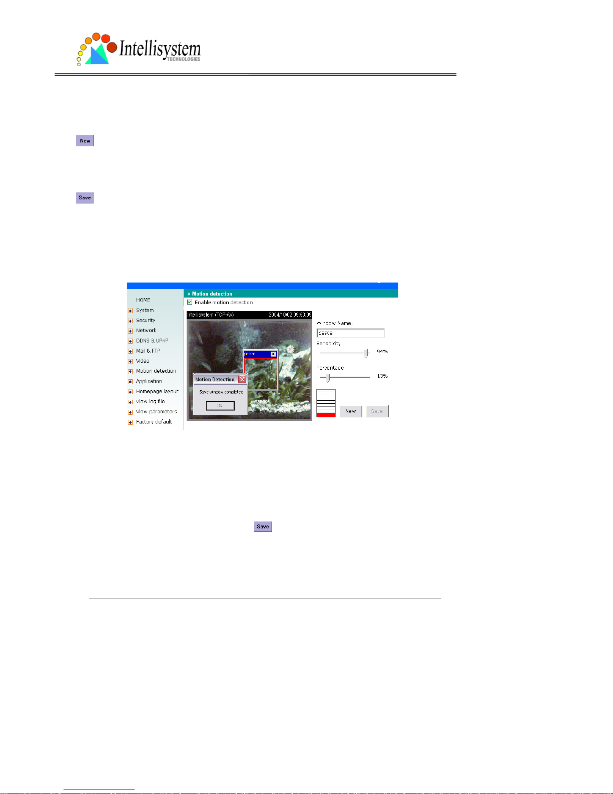
Motion detection
“Enable motion detection”, check this option to turn on the motion d etection.
, click on this button to add a new win dow. At most three windo w s can exist at the same
time. Use the mouse to drag the win dow frame to resize or th e title bar to move. Clicking on the
‘x’ at the upper right corner of the window can delete the window. Remember to save to
validate the changes.
, click on this button to sa ve the related settings reg arding to the window. A graphic bar will
rise or fall depending on th e i mag e variation. A green bar means the imag e variation is under
monitoring level and a red bar means t he ima ge variation is over moni t oring level . When the
bar goes red, the detected window will also be outlined in red. While back to the homepage, the
monitored window will hide but the red frame will show when motion is detected.
"Window Name", the text will show at the top of the window.“Sensitivity”, it sets the endurable
difference between two sequential images.
“Percentage”, it decides the space ratio of motioned objects over the monitored window. Higher
sensitivity and small percentage will make motion easier detected.
The following figure shows the screen when
is clicked. The monitoring window has been
outlined in red and the graphic bar goes red since the fish is moving.
Page 47

IT150W User’s Manual
Intellisystem Technologies - http://www.intellisystem.it
44
Application Setup
Weekly schedule
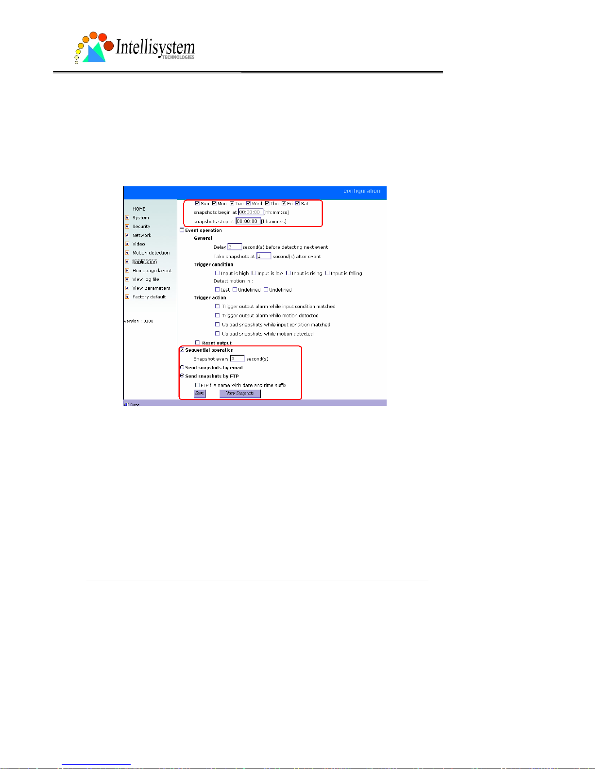
“Sun” ~ “Sat”, select the weekdays that should perform the foll owing operations.
“Snapshots begin at”, set the time to start oper ations. Setti ng begin time a s same as stop ti me
will perform operations 24 hours.
“Snapshots stop at”, set the time to stop operations.
Event operation
“Delay second(s) before detecting next event”, set the time delay before restarting to check
the trigger condition when the current condition is triggered.
“Take snapshots at second(s ) after event”, when a snapshot is taken upon the condition is
triggered, another snapshot will be taken aft er the configured seconds.
“Trigger condition”, there are four conditions related to the digital input and three windows for
motion detection. They can be multiple sel ected. Select the appropri ate digital in put condition
according to the characteristics of the external device. “high”, “low” indicate external voltage
input or not for level trigger whi le “rising” , “fal ling” is for edge trigger. There are three windows
shown as the name for motio n dete ction. “u ndef ined” will show instead of the window title if
motion detection is n ot setu p ye t . In su ch ca se , cli c ki ng on the “ Mot i o n de te cti on ” i n th e no te
can direct to the configuration page of motion detection.
“T ri gger action”, there are four option s for two actions r egardin g to eith er condi tion. The y can
be multiple selected. While cho osing trigger output alarm, the dig ital output will short both pins
to connect the circuit of the attached external device; otherwise both pins will be open. While
choosing to upload snap shots, the method can be either email or FTP. The snapshot name s will
be “videopre.jpg”, videotrg.jpg”, and “videopos.jpg” respectively for the snapshots before
event, right upon event, and after event. The date and time suffix may be added according to
the option. Confirm the external mail or FTP server settings in network configuration.
“Reset output”, check and save this option to reset the external device at the digital output
back to the original state.
Sequential operation
“Snapshot every second(s)”, the IT150W Network Camera will send snapshots at the specified
Page 48

IT150W User’s Manual
Intellisystem Technologies - http://www.intellisystem.it
45
interval to the external server according to the chosen method. Remember this operation is still
subject to the weekly schedule.
“Send snapshots by email”, any uploa d action specified in the options above will use the
method chosen here. The captured snapshot named “video.jpg” will be attached in the email
with subject “Periodic snapshots”.
“Send snapshots by FTP”, the captured snapshots will upload to the external FTP server with
the file name depending on the next option. It can be used to refresh the captured image stored
in the external web server to build creative homepages.
“FTP put snapshots with date and time suffix”, if the suffix is added, the captured date and time
can be easily differentiated from the snapshot file name in either sequential or ev ent operation.
For instance, “video@20020102030405.jpg” means the JPEG image was captured at 4 minutes
and 5 seconds after 3 o’clock, January 1st, A.D. 2002. If the suffix is omitted, the file named
“video.jpg” on the external FTP server wil l be r efreshed at the specified interval.
Homepage layout settings
“Use the customized homepage”, check this option to use “user.htm” uploaded by
administrators instead of the default one. Refer to the section “Administrator’s capability” for
detail usage. The following options related to the default homepage will not affect the
“user.htm”.
“Logo graph”, the logo located at the upper left corner of homepage can be hidden, the default
one that can be changed by administrators, or any image on the Internet that can be located
via URL. The default logo i s stored in memor y and can be ch anged by FTP. The maximal size is
32000 bytes. Though the file name is fixed to “lo go.gif ”, the image can be any file format as
long as the web browser can read it. R efer to the section “ Administr ator’s cap ability” for how to
change the default logo.
“Logo link”, when users click on the logo image, a new window will pop up to show the
homepage of the given URL. Clear the URL will disable the link function.
“Background graph”, t he backgroun d image can be hidd en to show the backgroun d color only,
the default one that can be ch anged b y ad ministrators, or any image on the I nter net that can
be located via URL. The default background image is stored in memory and can be changed by
FTP . The maximal size is 131000 bytes. Though the file name is fixed to “wallppr .jpg”, it can be
any file format as long as the web browser can rea d it. Refer to the section “Administrator’s
capability” for how to change the background image.
”Font color", pull down the list to select any color for the text i n the homepag e.
”Background color", pull down the list to select any color for the homepage background. It can
Page 49

IT150W User’s Manual
Intellisystem Technologies - http://www.intellisystem.it
46
be seen when the background image is not displayed.
Viewing system log
Click the link on the configuration page to view the system log file. The content of the file
reveals useful information about configuration and connection after the system boots up.
Viewing system parameters
Click the link on the conf iguratio n p age to quickly view the whole sy stem parameter set. The
content is the same as CONFIG.INI.
Restore factory default settings
Click the link on the configuration page to restore the factory default settings. This means any
changes made before wi ll be lost and the syst em will be reset to the initial status when shipped
from the factory . After confirmation, the system will restart and require t he installer progra m to
setup the network.
Page 50

IT150W User’s Manual
Intellisystem Technologies - http://www.intellisystem.it
47
Appendix
A. Troubleshooting
Status LED
After the power has been turned on, the IT150W Network Camera will perform a self-diagnostic
to detect any hardw are defects. The follow ing table lists the LED patterns in general conditions.
In case of any fatal error, the LED will blink in another pattern.
Condition LED color
During self-diagnost ic after power on Blink in interchanged green and re d
Ethernet signal is lost Steady red till Ethernet is detected
Before network is setup Steady green till IP address is confirmed
After network is setup Blink green every second
Any hardware failure Other patterns
Reset and restore
There is a button hidden in the pinhole beside the Ethernet socket. It is used to reset the
system or restore the factory default settings. Sometimes resetting the system can make the
system back to normal state. If the system still has problems after reset, restore the factory
settings and install again.
Restore the factory
defaults will lose any previous
settings. Reset or restore the
system after power on.
Page 51

IT150W User’s Manual
Intellisystem Technologies - http://www.intellisystem.it
51
RESET: Poke the wrench to click on the button.
RESTORE: 1. Poke the wrench to press on the button con tinuously.
2. Wait for self-diagnostic to run twice.
3. Withdraw the wrench as soon as the second self-diagnostic starts.
Page 52

IT150W User’s Manual
Intellisystem Technologies - http://www.intellisystem.it
52
B. Frequently asked questions
Q What if I forget my password?
A After the administrat or's password i s assigned, every access to the IT 150W Network Camera
needs authentication. If you are one of the managed users, you have to ask the administrator
for the password. If you are the administrator, there is no way to recover the root password
except for restoring factory default. Refer to Appendix A for the procedures.
Q Why can I not watch video from the IT150W Network Camera after it is authenticated?
A There are many possible scenarios regarding this proble m,
1. If you have just installe d t he IT150 W Netwo rk Camera and are unable to watch the video,
check if the heartbeat LED is blinking or the lens cap is removed. If the heartbeat LED is dim,
perform the softwar e inst a ll at ion ag ain .
2. If the IT150W Network C amer a is well in stalled an d you are acces sing the I T150W Ne twork
Camera for the first time using Internet Explorer , adjust th e securit y lev el of Int ernet E xplorer
to allow installation of plug-ins.
3. If the problem still exists after adjusting, and the message over the image window is
showing "connecting", the network traffic may be too crowded.
Q What is the plug-in for?
A The plug-in provided by the IT150W Networ k Camera i s used to displ ay motion p ictures an d
audio in Internet Explorer. If your system does not allow installation of any plug-in software,
the security level of the web browser may need to be lowered. It is recommended that you
consult your net work supervisors in you r office regarding adjustment of the security level.
Software installation may be regulated in some offices.
Q Why is the timestamp different from the system time of my PC or notebook?
A The timestamp is based on the system time of the IT150W Network Camera. It is maintained
by a real-time clock inside and can be automatically synchronized with the time server if the
IT150W Network Camera is connected to the Internet and the function is enabled. Differences
of several hours may result from the time zone se tting.
Q Can I install it on ceiling?
A Yes. There are flip and mirror options in video configuration page to correct the images for
upside down installation.
Page 53

IT150W User’s Manual
Intellisystem Technologies - http://www.intellisystem.it
53
Q The image is not clear enough.
A Rotate the lens to adjust the focus after the IT150W Network Camera is installed in the
proper position. The image settings an d white balance can be fine tuned to achieve the best
visual effect. Also notic e t he pow e r l ine freq ue ncy m ust ma tc h t he loca l ut i lity to sy nc hro niz e
the florescent lights to eliminate the uncomfortable flashin g.
Q Why does the image not refresh regularly?
A Some anti-virus programs will provide functions to filter the received web content. It will take
time to perform the data examination and affect the streaming application such as the IT150W
Network Camera. How ever it only aff ects the HTP mode of the IT150W Net work Camera. If the
network allows the HT TP mode only , dis able the web filtering function of the anti-virus pr ogram
temporarily. During the period, users should take the ri s k of malicious network activity.
Q I have opened motion detection windows but it cannot work.
A If the motion detection windows are setup and names are given, check if the function is
checked at the first line. While it is enabled, adjust the sensitivity and percentage to monitor
the level indicator if the threshold is appropriate.
Q I cannot hear any sound while watching.
A If there is "V_ONLY" shown above the image, click on connec tion type to unc heck "Disab le
audio". If there is "V" shown instead of "AV", the sound card in your PC may not properly
installed. If "AV" is shown, check the audio s ource of the IT150W Network C amera.
Q How many users are allowed to watch the IT150W Network Camera at the same time?
A Too many users requesting the real-time multimedia content will digest the network. To
achieve the best effect, the IT150W Network Ca me ra is designed to accommo dat e max imum
ten users to watch and listen to the IT150W Network Camera at the same time. It is
recommended to build another web server to host a large quantity of users by retrieving
contents from the IT150W Network Camera periodically.
Q How fast is the video rate of the IT150W Network Camera?
A The MPEG4 codec engine can process 30 frames per second internally. However the total
performance is subject to many coefficients as follows:
1. Network throughput,
2. Bandwidth share,
Page 54

IT150W User’s Manual
Intellisystem Technologies - http://www.intellisystem.it
54
3. Number of users,
4. The complicated objects and movement in view,
5. The level of your PC or notebook which is responsible for dis p laying ima ge s .
In general, the transfer rate in a general local network environment can ac hieve over 200
kilobytes per second an d approximately 10 to 20 pictures of a n ormal environmen t per second.
Q How can I keep the IT150W Network Camera as private as possible?
A The IT150W Ne twork Camera is designed for surveillance pur poses and has many flexibl e
interfaces. The user authentication and special confirmation in installation can keep the
IT150W Network Camera from unauthorized access. You may also change the HTTP port to
non-public number . The demo account is good to separate guests from normal users and thus
you can easily block guests anytime. You can check the system log to examine any abnormal
activities and trace the origins.
Q Why can I not access the IT150W Network Camera when I setup some options in the
application?
A Since the IT150W Network Camera is a "IT150W", any incorrect network settings will make
it unreachable. Once the system is missed due to wrong configuration, restore the factory
default settings following procedures in Appendix A.
Formattati:
Elenchi puntati
e numerati
Page 55

IT150W User’s Manual
Intellisystem Technologies - http://www.intellisystem.it
55
C URL commands of the IT150W Network Camera
For some customers who already have their own web site or web control application, the
IT150W Network Camera can be easily integrated through convenient URLs. This section lists
the commands in URL format corresponding to the basic functions of the IT150W Network
Camera.
Capture update Snapshot of JPEG image
/cgi-bin/video.jpg
The IT150W Network Camera will return the most up-to-date snapshot in JPEG format.
Query status of the digital input
/cgi-bin/getdi.cgi
The IT150W Network Camera will return the status of digital input.
Drive the digital output
/cgi-bin/setdo.cgi?do=<state>
, where state is H, L. H means NC connected with COMMON and L means NO connected with
COMMON.
For instance, typing http://192.168.0.201/cgi-bin/setdo.cgi?do=h
in address bar of the web
browser will command the IT150W Network Camera, with IP address of 192.168.0.201, set
digital output to connect to NC with COMMON.
Restore factory default settings
/setup/restore.cgi
The IT150W Network Camera will automatically restart after restoring factory default
configurations.
Page 56

IT150W User’s Manual
Intellisystem Technologies - http://www.intellisystem.it
56
Restart system
/setup/reset.cgi
Restart the IT150W Network Camera without warning.
Page URL
The configuration page has a frame layout including an option list frame and an option page
frame. Referenced URLs, except for the co nfiguration page, direct use rs to the option page
frame only. Some pages, like image qua lity setting and preset setting, are opened in new
windows for preview.
These URLs can be accessed only by administrators.
Homepage name Referenced URL
connection type page /client.html
configuration page /setup/config.html
system option /setup/system. html
security option /setup/security.html
network option /setup/network.html
video option /setup/video.html
motion detection /setup/motion.html
image quality option /setup/image.html
application option /setup/app.html
homepage layout option /setup/layout.html
system log /setup/logfile.html
system parameters /setup/parafile.html
set factory default /setup/factory.h tml
Page 57

IT150W User’s Manual
Intellisystem Technologies - http://www.intellisystem.it
57
System resource URL
There are some images used on the homepage when the homepage layout is in imag e m ode.
Administrators may use the following links to show the images saved in the IT150W Network
Camera on another page.
Resource name Referenced URL
system logo image /pic/logo.gif
background image /pic/wallppr.jpg
General format of command URL
Every configuration can be set through URL with POST method by administrators only.
<general format>
URL[?[name=value][&name=value]……]
<method>
POST
<authorized user >
root
System configuration URL
URL: /setup/system.cgi
NAME VALUE DESCRIPTION
host <text string shorter than 15
characters>
system name
yes turn off front LED Ledoff
no turn off front LED
keep keep date and time unchanged
auto use NTP server to synchronize
method
manu directly adjust date and time
date <yyyy/mm/dd> year, month and date separated by slash
time <hh:mm:ss> hour, minute and second separated by
colon
ntp <domain name or IP address> NTP server
Page 58

IT150W User’s Manual
Intellisystem Technologies - http://www.intellisystem.it
58
zone -12 ~ 12 time zone, 8 means GMT +8:00
Security configuration URL
URL: /setup/security.cgi
NAME VALUE DESCRIPTION
rootpass <text string shorter than 15
characters>
change root password
username <text string shorter than 15
characters>
add new user
userpass <text string shorter than 15
characters>
new user's password
deluser <text string shorter than 15
characters>
existing user name
action <blank> validate demo users with “open”
yes grant for demo account open
no prohibit for demo account
yes permission for DIDO access dido
no prohibit for DIDO access
Page 59

IT150W User’s Manual
Intellisystem Technologies - http://www.intellisystem.it
59
Network configuration URL
URL: /setup/network.cgi
NAME VALUE DESCRIPTION
yes enable installation at next boot reset
no disable installation at next boot
ip <IP address> The IT150W Network Camera's IP
address
subnet <IP address> subnet mask
router <IP address> default gateway
dns1 <IP address> primary DNS server
dns2 <IP address> secondary DNS server
http <number less than 65535> HTTP port
cport <number less than 65535> control Channel port
vport <number less than 65535> video Channel port
aport <number less than 65535> audio Ch annel port
yes optimal for the low bandwidth band
no keep the original way
ssid <text string shorter than 33
characters>
WLAN SSID
inf WLAN infrastructure mode wl
ad WLAN Ad Hoc mode
1 ~ 11 channel in USA
1 ~ 11 channel in Canada
1 ~ 13 channel in Europe
10, 11 channel in Spain
10 ~ 13 channel in France
chan
1 ~ 14 channel in Japan (all)
1 1 Mbps transmission rate
2 2 Mbps transmission rate
tx
3 5.5 Mbps transmi ssion rate
Page 60

IT150W User’s Manual
Intellisystem Technologies - http://www.intellisystem.it
60
4 11 Mbps transmissi on rate
5 22 Mbps transmissi on rate
l long preamble preamb
s short preamble
yes enable data encryption encr
no disable data encryption
auto auto authentication
shared shared-key authentication
auth
open open-key authentication
1 64 bits key length
2 128 bits key length
klen
3 256 bits key length
h hexadecimal format of key kform
a ASCII format of key
dkey 1 ~ 4 one of four keys
netkey1 hexadecimal string (00 ~ FF) network key 1
netkey2 hexadecimal string (00 ~ FF) network key 2
netkey3 hexadecimal string (00 ~ FF) network key 3
netkey4 hexadecimal string (00 ~ FF) network key 4
*Hexadecimal string means the string is composed of two-digit ASCII code indicating the
hexadecimal value. For example, if the network key is “abcdefg” in ASCII format, the
hexadecimal string will be “61626364656667”.
Page 61

IT150W User’s Manual
Intellisystem Technologies - http://www.intellisystem.it
61
Mail&FTP configuration URL
URL: /setup/mailftp.cgi
NAME VALUE DESCRIPTION
smtp1 <domain name or IP address> primary SMTP server
mailto1 <string shorter than 80
characters>
mail recipient address
smtp2 <domain name or IP address> secondary SMTP server
mailto2 <text string shorter than 80
characters>
mail recipient address
returnemail <text string shorter than 80
characters>
return email address
ftpp <number less than 65535> FTP port
ftp1 <domain name or IP address> primary FTP server
ftpuser1 <text string shorter than 15
characters>
user name for primary FTP server
ftppass1 <text string shorter than 15
characters>
password for primary FTP server
ftpfolder1 <text string shorter than 40
characters>
upload folder in primary FTP server
ftp2 <domain name or IP address> secondary FTP server
ftpuser2 <text string shorter than 15
characters>
user name for secondary FTP server
ftppass2 <text string shorter than 15
characters>
password for secondary FTP server
ftpfolder2 <text string shorter than 40
characters>
upload folder in secondary FTP server
Page 62

IT150W User’s Manual
Intellisystem Technologies - http://www.intellisystem.it
62
Video configuration URL
URL: /setup/video.cgi
NAME VALUE DESCRIPTION
text <text string shorter than 15
characters>
enclosed capti on
1 half
2 half x 2
size
3 normal
B/W monochrome color
<other than B/W> color
fixb fix bit rate quality
<other than fixb> fix quantization
1 lowest quality of video
2 lower quality of video
3 normal quality of video
4 higher quality of video
quan
5 highest quality of video
64000 set bit rate to 64K bps
128000 set bit rate to 128K bps
256000 set bit rate to 256K bps
384000 set bit rate to 384K bps
512000 set bit rate to 512K bps
768000 set bit rate to 768K bps
1000000 set bit rate to 1000K bps
bitrate
1200000 set bit rate to 1200K bps
1 set maxi mum frame rate to 1 fps
2 set maxi mum frame rate to 2 fps
3 set maxi mum frame rate to 3 fps
5 set maxi mum frame rate to 5 fps
10 set maximum frame rate to 10 fps
15 set maximum frame rate to 15 fps
20 set maximum frame rate to 20 fps
frame
25 set maximum frame rate to 25 fps
Page 63

IT150W User’s Manual
Intellisystem Technologies - http://www.intellisystem.it
63
30 set maximum frame rate to 30 fps
50Hz synchronize with 50Hz utility mode
60Hz synchronize with 60Hz utility
1 auto white balance
2 fixed indoor(2800K)
3 fixed fluorescent 1(3600K)
4 fixed fluorescent 2(4000K)
wb
5 fixed outdoor(6000K)
yes flip image flip
no normal image
yes mirror image mirror
no normal image
Page 64

IT150W User’s Manual
Intellisystem Technologies - http://www.intellisystem.it
64
Image quality configuration URL
URL: /setup/image.cgi
NAME VALUE DESCRIPTION
brightness <-5 ~ 5> adjust brightness of image
contrast <-5 ~ 5> adjust contrast of image
hue <-5 ~ 5> adjust hue of image
saturation <-5 ~ 5> adjust saturation of image
preview <not required> not save the parameters
restore <not required> recall the original settings
save <not required> save the parameters
Application configuration URL
URL: /setup/app.cgi
NAME VALUE DESCRIPTION
emode <not required> event mode application
smode <not required> sequential mode application
mail upload snapshots by email smethod
ftp upload snapshots by FTP
suffix <not required> FTP file with date and time suffix
delay <integer> seconds delay to detect next event
inter <integer> seconds delay to capture post-event
dihigh < not required > set DI high as trigger condition
dilow < not required > set DI low as trigger condition
dirise < not required > set DI rising as trigger condition
difall < not required > set DI falling as trigger cond ition
motion1 < not required > set motion window1 as trigger condition
motion2 < not required > set motion window2 as trigger condition
motion3 < not required > set motion window3 as trigger condition
ioalarm < not required > trigger DO when DI condition matched
mdalarm < not required > trigger DO when motion detected
Page 65

IT150W User’s Manual
Intellisystem Technologies - http://www.intellisystem.it
65
ioupload < not required > upload snapshot when DI condition
matched
mdupload < not required > upload snapshot when motion detected
sinter <integer> seconds interval for sequential mode
sbegin <hh:mm:ss> time to start sequential mode
send <hh:mm:ss> time to stop sequential mode
Homepage layout configuration URL
URL: /setup/layout.cgi
NAME VALUE DESCRIPTION
blank hide logo
def use default logo
cuslogo
url use image from URL
logourl <text string shorter than 80
characters>
URL of image for logo
linkurl <text string shorter than 80
characters>
URL to link when clicking on logo
blank hide background image
def use default background
cusback
url use image from URL
backurl <text string shorter than 80
characters>
URL of image for background
fcolor <0 ~ 15> color index for font
bcolor <0 ~ 15> color index for background
Page 66

IT150W User’s Manual
Intellisystem Technologies - http://www.intellisystem.it
66
D. Technical specifications
- Remote management
Configuration and system log can be accessed via Web
browser and FTP application remotely
- Networking
Protocol
TCP/IP, HTTP, SMTP, FTP, Telnet, NTP, DNS and DHCP
Ethernet
10BaseT or 100BaseT Fast Ethernet
- Video
Algorithm supported
MPEG4(short header mode)
Features
Three adjustable image size and quality
Intelligent motion detection windows
Flexible bit rate
- Audio
24Kbps, 8Kbps(optional)
- Video resolution
Up to 30 frames at 160x120
Up to 30 frames at 320x240
Up to 10 frames at 640x480
Full screen mode(depends on PC display chip)
- General I/O
1 opto-isolated sensor input(max. 12VDC 50mA)
1 relay output(max. 24VDC 1A, 125VAC 0.5A)
- Security
Administrator and user group protected
Password authentication
- LED indicator
Bi-color status indicator
- Camera specification
1/3 inch color CM OS sensor
640x480
2.5Lux/F1.4
AGC/AWB
Electronic shutter: 1/60 ~ 1/15000 second
Standard CS mount type lens, 6mm, F1.8
- Power
12VDC 1.2A, external power supply
Power Consumption near 8,4 W
- Weight
About 240g
- Dimension
143,5mm(L)x89mm(W)x57mm(H)
- Viewing system requirement
Protocol
Standard Internet TCP/IP suite
Operating system
Microsoft Windows
Browser
Internet Explorer 5.x or above
Page 67

IT150W User Manual – Ver 1.2
Intellisystem Technologies S.r.l. - http://www.intellisystem.it
67
Electromagnetic Compatibility (EMC)
USA - This equipment has been tested and found to comply with the limits for a Class B digital
device, pursuant to Part 15 of the FCC Rules. These limits are designed to provide reasonable
protection against harmful interference in a residential installation. This equipment generates,
uses and can radiate radio frequency energy and, if not install ed and u sed in a cco rdan ce wit h
the instructions, may cause harmful interference to radio communications. However, there is
no guarantee that interference will not occ ur in a partial installat ion. If this equipment does
cause harmful interference to radio or television reception, which can be determined by turning
the equipment off and on, the user is encouraged to try to correct the interference by one or
more of the following measures:
-- Reorient or relocate the receiv ing antenna.
-- Increase the seperation between the equipment and r ecei ver.
-- Connect the equipment in to an outl et on a circui t different fr om that to whi ch the rece iver is
connected.
-- Consult the dealer or an experienced radio/TV technician for help.
Shielded interface cables must be used in order to comply with emission limits.
Eutope - This digital equipment fulfills the requirement for radiated emissi on according to
limit B of EN55022/1998, and the requirement for immunity according to EN50082-1/1992
.
Liability
Intellisystem Techn olog ies S.r.l. can not b e held r espon sib le f or an y t echni cal or t ypogr ap hic al
errors and reserves the righ t to make changes to the produ ct and manuals without p rior notice.
Intellisystem Techno logies S.r.l. ma kes no warranty of any kind with re gard to the materi al
contained within this document, including, but not limited to, the implied warranties of
merchantability and fitness for a particular purpose. All other company names and products are
trademark or registere d trademarks of their respective companies.
Page 68

IT150W User Manual – Ver 1.2
Intellisystem Technologies S.r.l. - http://www.intellisystem.it
67
For any question and support please contact:
Intellisystem Technologies S.r.l.
Support: info@intellisystem.it
Web Site: http://www.intellisystem.it
Page 69

IT150W User Manual – Ver 1.2
Intellisystem Technologies S.r.l. - http://www.intellisystem.it
67
NOTES:
 Loading...