

Page 1

Page 2

Table of Contents
SAFETY AND REGULATORY NOTICES .....................................................3
1: PRODUCT OVERVIEW.........................................................................6
1.1
NETWORK CAMERAS ............................................................................6
NETWORK VIDEO SERVERS....................................................................7
1.2
1.3
MODEL OVERVIEW..............................................................................7
2: SYSTEM REQUIREMENTS ...................................................................9
2.1
HARDWARE REQUIREMENTS ...................................................................9
2.2
OPERATING SYSTEM AND WEB BROWSER SUPPORT .......................................9
2.3
LIMITATIONS................................................................................... 10
3: HARDWARE OVERVIEW ...................................................................11
3.1
FRONT & REAR ................................................................................ 11
3.1.1 NSC15/NSC15-WG/NSC16-WG Network SOHO Cameras............. 1 1
3.1.2 NFC30/NFC31 Network Fixed Cameras ..................................... 13
3.1.3 NFD30 Network Dome Camera ................................................15
3.1.4 NBC30-IR Outdoor Network Camera......................................... 17
3.1.5 NVS30 Network Video Server ..................................................19
3.2
DIGITAL I/O TERMINAL BLOCK CONNECTOR.............................................. 21
3.3
PACKAGE CONTENTS..........................................................................22
4: INSTALLATION................................................................................23
4.1
CONNECTING TO THE CAMERA ..............................................................23
4.1.1 Windows XP, Vista and Windows 7 ........................................... 24
4.1.2 MacOS.................................................................................. 41
4.1.3 Linux....................................................................................43
5: WEB BROWSER INTERFACE .............................................................44
5.1
LIVE VIDEO PAGE............................................................................. 44
5.2
SETTINGS PAGE (ADMINISTRATOR MENU)................................................ 48
5.2.1 Settings Page – Basic Settings................................................. 48
5.2.2 Settings Page – Advanced Settings ..........................................81
6: VIDEO SURVEILLANCE SOFTWARE ................................................102
6.1
FUNCTION DESCRIPTION................................................................... 102
6.2
INSTALLATION ............................................................................... 102
7: REMOTE ACCESS AND ROUTER SETUP ...........................................103
8: DEVELOPER INFORMATION ...........................................................105
9: QUESTIONS AND ANSWERS...........................................................107
9.1
ACCESSING THE CAMERA ..................................................................107
9.2
WEB BROWSER ACCESS ................................................................... 108
9.3
CAMERA RELATED ISSUES .................................................................109
- 2 -
Page 3

Safety and Regulatory Notices
Thank you for purchasing this INTELLINET NETWORK
SOLUTIONS™ Network Camera or Network Video Server. This
user manual includes instructions for using and managing the
camera on your network. Experience in networking will be
helpful when setting up and using this product. Updated
versions of this document will be posted to www.intellinet network.com as they become available. The latest version of
this user manual can also be found on the Installation CD
accompanying this product, along with user manuals in other
languages.
Operation of this equipment in a residential area is likely to cause interference,
in which case the user, at his own expense, will be required to take whatever
measures may be required to correct the interference. This digital equipment
fulfills the requirements for radiated emission according to limit B of
EN55022/1998, and the requirements for immunity according to EN55024/1998
residential, commercial and light industry.
R&TTE Compliance Statement
and Satellite Earth Station Equipment) as of April 8, 2000.
Safety
This equipment complies with EN 60950, Safety of Information Technology
equipment.
This equipment has been tested and found to comply with the
limits for a Class B computing device pursuant to Subpart B of
Part 15 of FCC rules, which are designed to provide reasonable
protection against such interference when operated in a
commercial environment.
This equipment complies with all the requirements of DIRECTIVE
1999/5/EC OF THE EUROPEAN PARLIAMENT AND THE COUNCIL of
March 9, 1999 on radio equipment and telecommunication
terminal Equipment and the mutual recog nition of their conformity
(R&TTE). The R&TTE Directive repeals and replaces in the
directive 98/13/EEC (Telecommunications Terminal Equipment
- 3 -
Page 4

Waste Electrical & Electronic Equipment
Disposal of Electric and Electronic Equipment
(Applicable in the European U n ion and other European countries with
separate collection systems)
batteries or accumulators, dispose of these separately acc ording to your local
requirements. The recycling of materials will help to conserve natural
resources. For more detailed information about recycling of this product,
contact your local city office, your household waste disposal servic e or the shop
where you purchased this product. In countries outside of the EU: If you wish
to discard this product, contact your local authorities and ask for the correct
manner of disposal.
Electromagnetic Compatibility (EMC)
This equipment generates radio frequency energy and, if not installed and used
in accordance with the instructions, may cause harmful interference to radio
communications. However, there is no guarantee that interference will not
occur in a particular installation. If this equipment does cause harmful
interference to radio or television reception, which can be determined by
turning the equipment off and on, the user is e nco uraged to try to correct the
interference by one or more of the following measures:
- Re-orient or relocate the receiving antenna
- Increase the separation between the equipment and receiver
- Connect the equipment to an outlet on a different circuit than the
- Consult your dealer or an experienced radio/TV technician for help
- Check that shielded (STP) network cables are being used with this unit
EU Countries Intended for Use
The ETSI version of this device is intended for home and office use in Austria,
Belgium, Denmark, Finland, France, Germany, Greece, Ireland, Italy,
Luxembourg, the Netherlands, Portugal, Spain, Sweden, and the United
Kingdom.
The ETSI version of this device is also authorized for use in EFTA member
states: Iceland, Liechtenstein, Norway, and Switzerland.
EU Countries Not intended for use
None.
This symbol on the product or its packaging indicates that this
product shall not be treated as household waste.
Instead, it should be taken to an applicable collection point for the
recycling of electrical and electronic equipment. By ensuring this
product is disposed of correctly, you will help prevent potential
negative consequences to the environment and human health,
which could otherwise be caused by inappropriate waste handling
of this product. If your equipment contains easily removable
receiver
to ensure compliance with EMC standards
- 4 -
Page 5

Important Information
1. Camera surveillance laws may differ for each country. Contact the local
authorities to avoid any surveilla nce law violations.
2. Note that the image sensor of this network camera can be damaged
permanently if exposed to direct sunlight. Defective image sensors that
have been damaged by prolonged exposure to direct sunlight are excluded
from the product warranty.
3. Indoor network cameras are not weatherproof. Refer to the environmental
specifications included in the back of this manual. For outdoor use, use a
weatherproof case to protect the camera from water, moisture or
temperature (higher or lower than specifications). To keep the camer a
clean, gently wipe it with a clean, dry cloth.
4. Be sure to use only the DC adapter provided with your camera. If your
network camera supports Power over Ethernet (see the product
information at the end of this user manual for details), you can use an IEEE
802.3af-compliant PoE injector (mid- or endspan) to provide power to the
camera.
5. Always handle the camera with care, as physical shocks can cause serious
damage to the hardware.
6. Be sure to mount the camera securely to avoid any personal injuries. Keep
the camera out of the reach of children.
7. If the camera does not operate properly, contact your local distributor. Do
not disassemble the product, as that will void the warranty.
8. Technical product support is provided by your dealer or distributor via email and phone. Additional technical support is provided by INTELLINET
NETWORK SOLUTIONS via the Web site www.intellinet-network.com.
9. Before contacting technical support, be sure to verify that your camera has
the latest firmware version installed (you can access the camera’s system
information page to find out). To expedite your technical support request,
it is recommended to include a very detailed error description in your
message.
10. Should the camera not power up upon initial installation, you need to
discontinue the use of the product immediately.
11. Returns and replacements of defectiv e products are handled by our
network of authorized dealers. Contact the place of purchase.
12. Used cameras, especially those that they were purchased on auction Web
sites, are excluded from the product warranty.
- 5 -
Page 6

1: Product Overview
1.1 Network Cameras
Network cameras are closed-circuit television (CCTV) cameras that use the
Internet Protocol (TCP/IP) to transmit image data over an Ethernet or Wireless
LAN connection. As such, network cameras are also referred to as IP cameras.
IP cameras are primarily used for surveillance applications. A number of IP
cameras are normally deployed together with a digital video recorder (DVR) or
a network video recorder (NVR) to form a video surveillance system. Since
network cameras are equipped with an operating system, they do not require
the presence of a DVR or NVR in order to function. In addition, a network
camera can transmit data in a local network as well as over the Internet.
Access to a network camera is typically achieved with a standard Web browser,
such as MS Internet Explorer or Firefox.
Example showing a wireless network camera in a typical setup
Example showing a network camera in a typical setup with an NVR recording
solution
- 6 -
Page 7

1.2 Network Video Servers
A network video server allows connection to an analog CCTV camera via coaxial
cable.
Example showing a CCTV camera connected to a network video server, which
itself is connected to the netw ork.
1.3 Model Overview
This user manual contains information for the following models:
1. NSC15/NSC15-WG
Motion-JPEG + MPEG4, Audio, 300k CMOS
NSC15-WG only: Day/Night, 54 Mbps Wireless 802.11g
2. NSC16-WG
Motion-JPEG + MPEG4 + H.264, Audio, 1.3M CMOS, Day/Night, 54 Mbps
Wireless 802.11g
3. NFC30/NFC30-WG
Motion-JPEG + MPEG4, Audio, 300k CMOS
NFC30-WG only: 54 Mbps Wireless 802.11g
IEEE 802.3af PoE Support for wired model NFC30.
4. NFC30-IR/NFC30-IRWG
Motion-JPEG + MPEG4, Audio, 300k CMOS, Day/Night, IR LEDs
NFC30-IRWG only: 54 Mbps Wireless 802.11g
IEEE 802.3af PoE Support for wired model NFC30-IR.
- 7 -
Page 8

5. NFC31/NFC31-WG
Motion-JPEG + MPEG4 + H.264, Audio, 1.3M CMOS
NFC31-WG only: 54 Mbps Wireless 802.11g
IEEE 802.3af PoE Support for wired model NFC31.
6. NFC31-IR/NFC31-IRWG
Motion-JPEG + MPEG4 + H.264, Audio, 1.3M CMOS,
Day/Night, IR LEDs
NFC31-IRWG only: 54 Mbps Wireless 802.11g
IEEE 802.3af PoE Support for wired model NFC31-IR.
7. NFD30
Motion-JPEG + MPEG4, Audio, 300k CMOS, IEEE 802.3af PoE Support
8. NBC30-IR
Motion-JPEG + MPEG4, Audio, 300k CMOS, Day/Night, IR LEDs, IEEE 802.3af
PoE Support
9. NVS30
Motion-JPEG + MPEG4, Audio, IEEE 802.3af PoE Support
- 8 -
Page 9

2: System Requirements
2.1 Hardware Requirements
Your computer hardware should meet or exceed the following
specifications:
Access to a single camera with Web browser:
CPU: Pentium 4 1600 MHz (or equivalent AMD)
Video Card: 64 MB graphic card
RAM: 512 MB
Network Adapter: 10/100 Mbps Fast Ethernet
Using the 16-Channel viewing / recording utility:
CPU: INTEL Dual Core Processor
Video Card: 64 MB graphic card
RAM: 2 GB
OS: Windows XP, Windows Vista or Windows 7
2.2 Operating System and Web Browser
Support
INTELLINET NETWORK SOLUTIONS network cameras support Web-browser
based access for all major operating systems.
• Windows 2000, Windows XP, Windows Vista and Windows 7
- MS Internet Explorer 7.x and 8.x (ActiveX & Java)
- Firefox 3.x (Java)
- Google Chrome (Java)
- Opera 9.x (Java)
• MacOS X Leopard
- Firefox 3.x (Java)
- Safari 3.x (Java)
• Linux
- Firefox 3.x (Java)
- Konqueror (Java)
- 9 -
Page 10

2.3 Limitations
Web Browser Access
While it is possible to connect to the network camera with a Web browser other
than MS Internet Explorer, some of the features cannot be used. Refer to the
overview below:
MS Internet Explorer 7.x and 8.x (ActiveX)
- view live video in all formats
- record live video by right-clicking the live video
- listen to audio
- use a microphone to send audio to the camera
- view the video in full-screen mode
- use the digital zoom function
- access the administrator menu and configure the camera
- setting up privacy masking, motion and audio detection
All other browsers (Java)
- view live video in Motion-JPE G format
- access the administrator menu and configure the camera
(with certain limitations)
IP Installer
This application is only compatible to Windows operating systems.
Installation on MacOS systems can be done using the Bonjour discovery service
while the installation on Linux systems requi r es manually changing the IP
address of the system to gain access to the camera. Refer to section 4.1
Connecting to the Camera for installa tion instructions.
16-Channel Viewing / Recording Utility
This application is only compatible to Windows operating systems. Visit
www.networkipcamera.com for a complete list of compatible applications.
- 10 -
Page 11

3: Hardware Overview
3.1 Front & Rear
The following pages provide an overview of the hardware
features of the different types of network cameras and the
network video server.
3.1.1 NSC15/NSC15-WG/NSC16-WG
Network SOHO Cameras
Front
The image above shows the options for the wireless models NSC15/16-WG. The
wireless antenna connector and the Night-Vision LEDs are exclusive to these
models and cannot be found on the wired model NSC15.
- 11 -
Page 12

Rear
Power Connector: The connection for the power adapter, which is
Reset Switch: If you need to perform a hardware reset, you can
Speaker: Stereo connector for the connection of active speakers
LAN: Connection for standard RJ45 Cat5 (or better) network
supplied with the camera.
insert a paper clip into the reset hole and depress the
switch for 10 seconds.
or other line-out audio sources.
cable. Maximum length is 100 m / 300 ft.
Connection of NSC15 to the network (wired)
- 12 -
Page 13

3.1.2 NFC30/NFC31 Network Fixed Cameras
Front
Top Mounting Point
1/3” CS-Mount Lens
Bottom Mounting Point
Camera Stand
Front IR Versions
The IR cameras are equipped with a fixed lens that
cannot be removed or replaced. The IR lens
features 12 IR LEDs that output a wavelength of
850 nm and allow the camera to capture video in
complete darkness.
- 13 -
Page 14

Rear
Microphone / Line-In Connector: Connector for external microphones or other
Wireless Antenna Connector: RP-SMA jack for the connection of external
Digital I/O Connector: Terminal block adapter for the connection of
Connection using IEEE 802.3af Power over Ethernet
line-in audio sources.
antennas, such as the one provided with your
wireless camera.
external alarm devices. The connector has two
inputs and two outputs.
Note: Connection using the power adapter is supported as well
- 14 -
.
Page 15

3.1.3 NFD30 Network Dome Camera
Power Connector: For connection of 12 V DC input.
Audio Out (Green Line): To support audio out with earphones or speakers
Audio In (Red Line): To support audio in for microphone.
Network Connector: For the connection to the RJ45 Ethernet cable. The
Network Indicator: Indicates that the camera has successfully
Network Transmit Indicator: Flashes to indicate network traffic.
Reset: If you need to perform a hardware reset, you can
I / O Terminal Connector: 1 Input and 1 Output to support External Alarm
for two-way audio.
connector supports IEEE802.3af-compliant PoE
input signals.
connected to the network.
insert a paper clip into the reset hole and depress
the switch for 10 seconds.
and Sensor devices used for motion detection,
event triggering and alarm notification.
- 15 -
Page 16

1: Connection using IEEE 802.3af Power over Ethernet.
2. Connection using a standard power adapter (1) and a regular LAN switch or
router (2).
- 16 -
Page 17

T
3.1.4 NBC30-IR Outdoor Network Camera
IP67-rated housing
Reset Switch
Audio In Audio Out
Infrared LEDs Cable Manager Bracket
12 V DC
erminal Block Connector
RJ45 Network Connector
- 17 -
Page 18

1: Connection using IEEE 802.3af Power over Ethernet.
2. Connection using a standard 12 V DC power adapter (1) and a regular LAN
switch or router (2). The power adapter is not included.
- 18 -
Page 19

3.1.5 NVS30 Network Video Server
Front
Video In: Input connector for analog CCTV camera.
Video Out: Loop-through port that outputs analog video, which
can be integrated into an existing CCTV surveillance
system.
Mic In: Microphone/Line-In input connector.
Line Out: Line-Out connector for active speakers.
I/O Terminal Connector: 1 Input and 1 Output to support External Alarm and
Sensor devices used for motion detection, event
triggering and alarm notification.
RS-485 Connector: Used to connect analog PTZ cameras to the video
server.
- 19 -
Page 20

Rear
PWR: LED lights up once the network video server has
successfully started up.
Power Connector: Connect the power adapter here, unless you wish to
utilize the Power over Ethernet functionality.
Network / PoE Connector: Standard RJ45 socket for Cat5 (or better) network
cable. IEEE 802.3af-compatible input sources are
supported.
Connection Diagram
Note: The NVS30 is a one-channel vid eo server. Only one CCTV camera can be
connected at a time.
- 20 -
Page 21
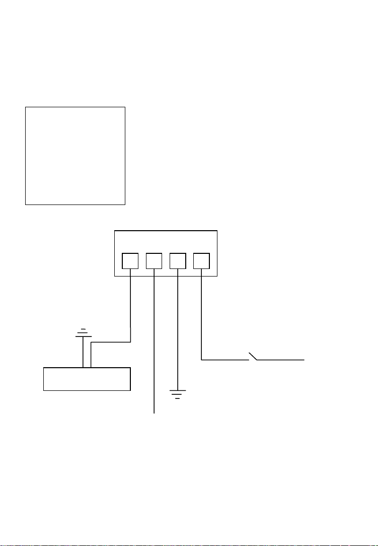
3.2 Digital I/O Terminal Block Connector
The Network Camera and Network Video Server, with the exception of the
NSC15 models, are equipped with a digital I/O interface. It can be used to
connect external alarm sensors (pins 1 and 2) or to power external devices
(pins 3 and 4).
From left to right: Pins 1 (DI+), 2 (DI-), 3 (Com) and 4 (No)
NO COM DI- DI+
Ground
Switch
12 V
Alarm out device
Ground
12 V
Max. 30 W
DI+: Digital Input (+), DI-: Digital Input GND (-)
Com: Power DC 12 V (+), No: Power GND (-)
The NVS30 Network Video Server features two additional pins 5 (+) and 6 (-)
that are used to connect analog CCTV camera with PTZ control (RS-485).
- 21 -
Page 22

3.3 Package Contents
You should find the following items in the packaging of your INTELLINET
NETWORK SOLUTIONS video surveillance product.
1. Network Camera (or Network Video Server)
2. User manual (this document) and Quick Installation Guide
3. Installation CD
4. Camera stand (all indoor NSCxx and NFCxx models)
5. Wall-Mount bracket (all outdoor NBCxx models)
6. Mounting hardware (NFSxx and NBCxx models)
7. Power adapter (except for NBC30 (550932))
-> Input: 110/230 V, 50/60 Hz
- 12 V DC (other models)
If any items are missing, contact your dealer.
-> User Manual in electronic form in different languages
-> IP Installer Utility
-> Multi-Channel IP Surveillance Utility
-> Output: - 5 V DC (NSC15 models)
- 22 -
Page 23

4: Installation
4.1 Connecting to the Camera
Connect the RJ45 network cable from th e camera’s LAN port to your network;
e.g., the router or a LAN switch, then power on the camera . The boot sequence
will take about one minute. You will need to use the camera’s power adapter,
unless your camera supports PoE (see section 1.3 Model Overview). In that
case you can connect the RJ45 cable to a PoE enabled switch or injector to
power the camera.
By default, the network camera (or video server) searches for a DHCP server
on the network and obtains an IP address automatically. A very common DHCP
server is a router, a device that is found on most networks.
The presence of a DHCP server on your network simplifies the installation and
users with limited knowledge of TCP/IP networks can install the network
camera in minutes. If no DHCP server is found, the network camera will revert
to its default IP address 192.168.1.221.
On Windows systems, you want to use the IP Installer utility t hat finds the
camera on the network and lets you make changes to the configuration.
Once the camera is set up properly, it can be accessed with the computer’s
Web browser. The following sections describe the procedure for Windows,
MacOS and Linux users.
- 23 -
Page 24

4.1.1 Windows XP, Vista and Windows 7
Insert the Installation CD into the CD or DVD-Drive.
After a few moments, the CD will automatically start
and display the screen below. If that does not happen,
you need to browse the CD with Windows Explorer and
double-click the autorun.exe file.
1. User Manuals
The user manual for the INTELLINET NETWORK SOLUTIONS Network
Camera is available in electronic form on the installation CD, along wit h
user manuals in different languages.
If you encounter differences between the screen shots show n in the user
manual and the actual screen contents, it is recommended that you open
the manual from the CD, as it may be a newer editio n than the printed
version.
2. IP Installer for Windows
This utility is designed to find the network camera on your network and lets
you make changes to the configuration.
3. Video Surveillance Software
Refer to Chapter 6 Video Surveillance Software.
- 24 -
Page 25

IP Installer for Windows Installation
Before you start with the installation, make sure that you are connected to
your computer with a user account that has administrator rights. The
screen shots below are taken from an installation on a Wind ows XP system.
The procedure on Vista and Windows 7 systems is similar.
To begin the installation, click on the link “IP Installer for Windows.” After
that, depending on your system’s settings, you may see t he message
shown below.
Click on “Run” to continue …
… and click on “Yes” to begin the installation.
Select your preferred installation language, and then click o n “Next.”
Click on “Next” on the following screen as well.
- 25 -
Page 26

Specify the location where the program should be installed. The default path is
OK to be used on most systems. Click on “Browse…” to select a different
location and click on “Next” to continue.
Select the Windows Start Menu folder.
Select or de-select the optional Xvid Codec and MSN Plugin. If you are not sure
about these options, it is recommended to keep them selected.
Click “Next” to continue.
- 26 -
Page 27

Verify the installation summary and click “Install” to begin the installation.
Once the installation has completed, click on “Finish”.
A new shortcut has been created on your computer
desktop; Double-click it to start the application.
- 27 -
Page 28

IP Installer for Windows
When the program starts, you are presented with the screen shown below.
Depending on your camera model, the screen may look slightly different, but
the functionality is the same. The IP Installe r utility lists all cameras that can be
found on your network. With this utility you can make changes to the
configuration, perform a firmware upgrade, restore the camera to factory
default values, and reboot the camera. Note: It may take up to three minutes
for IP Installer to show a camera that has been recently (re-)started.
The application has three main tabs: Camera, User and About.
Camera tab
UPnP device list: All cameras that are found on the network are displayed on
this tab. Cameras that are shown in red are currently
configured for a different network and cannot be accessed
with the Web browser before the IP settings of the camera
have been adjusted to your network (see Setup).
Search: The Search button can be used to refresh the view. Typically
it is not required to push the button, as the utility starts
scanning the network as soon as it is started.
Link to IE: Select the camera from the list and click this button to open
the camera with MS Internet Explorer. Note: This function
does not work for other Web browsers; however, you can
open the browser manually and open the URL
http://camera_ip_as_shown_in_list (in the example above,
you would open http://192.168.0.102).
- 28 -
Page 29

Setup: Select a camera from the list and click the Setup button in
Upgrade: Select a camera from the list and click the Upgrade button if
Factory default: If you want to reset the camera settings to factory default
order to open the camera configuration dialog.
you wish to upgrade the firmware of the camera. The
firmware upgrade can also be performed with your Web
browser.
values, you can select a camera from the device list and click
this button. When you do this, you will be asked to enter the
administrator user name and password:
Enter “admin” for both.
You will then see the following message:
Click Yes to perform the factory reset.
Reboot: This function lets you reboot the camera. The procedure is
identical to the factory default function, except the camera
does not lose the settings.
Camera Tab – Setup Function
When you click on the Setup button, you first need to enter a valid
administrator user name and password (see above). You will then be pres ented
with the first page of the Setup menu. The first page shows so me basic
information about the camera.
Click the Next button to open the next page.
- 29 -
Page 30

User Account Settings Page
User Name: Enter the user name you wish to use for the new account.
Password: Enter the password for the new user account.
Confirm: Type the password in again.
Mode: There are three possible values to choose from:
1. Admin: User has full access to all camera functions.
2. Operator: User can view the live image and change image
related settings such as brightness, contrast , etc.
3. Viewer: User can view the live video of th e camera, but is
unable to make any changes to the configuration.
Viewer
Authentication: On: Every user that connects to the camera has to enter a
valid user name and password.
Off: A user na me and password is only required if the user
wants to change camera-related settings. By setting the
Viewer authentication to off, you allow any user to view the
camera’s live image.
Click the Next button to open the next configuration page.
- 30 -
Page 31

Date/Time Settings Page
The network camera is equipped with an internal clock. You can display the
current date and time information on the video, so that when you look at
recorded video material or images you can easily tell when the recording was
made. Before you can use this function, you need to defin e how the camera
obtains the time.
Current Setting: Displays the current date and time.
PC clock: Displays the time of the PC that you are using right now.
Adjust: Keep current setting
Time Zone: Select the correct time zone for the camera to display the
Click the Next button to open the next configuration page.
Synchronize with PC
current date and time from the PC.
Manual setting
yourself.
Synchronize with NTP
an NTP server. Normally it is no t required to change the NTP
server, as the default server “pool.ntp.org” is always
available. You can, however, manually overwrite the NTP
server by un-checking the option “auto.”
Interval:
the time with the NTP server’s time.
correct date and time.
Define how often the camera should re-synchronize
– no changes are made.
– instructs the camera to retrieve the
- allows you to set up the date and time
– The camera will obtain the time from
- 31 -
Page 32

Network Settings Page
The default configuration is shown above, and for most users there should be
no need to change these settings. Advanced users can change the following
values:
HTTP Port: This is the Web server port of the camera. The default value
is 80. You can change the value from 80 to a value between
1024 and 65535. Note that when you change the HTTP port,
you need to append the new port to the address of the
camera; e.g., http://192.168.0.102:1024.
IP Address: By default the camera obtains the IP address from a DHCP
server in the network. You can set up the camera with a static
IP address as well by activating the option “Use the follow ing
IP.” If you are not familiar with IP addresses in general or the
IP address setup of your network, you should contact your
network administrator for the correct values.
DNS Setting: A DNS Server (DNS stands for Domain Name System) allows
the camera to contact an e-mail, FTP or NTP server using its
proper domain name (e.g., mail.mydomain.com) rather than
its IP address. If you set up the camera with a static IP
address, chances are that you will need to provide the DNS
server settings yourself as well.
Click the Next button to open the next configuration page.
- 32 -
Page 33

PPPoE Settings Page
This page allows defining of the PPPoE settings of the camera. This function is
not required for the vast majority of users, and if you are not planning on
connecting the camera directly to a DSL modem (no network present, just the
camera connects directly to the modem) you can safely skip this p a ge.
PPPoE is a common connection method for ADSL Internet services. It is not
required for cable modem service, or newer DSL services that operate with
dynamic IP addresses.
PPPoE connections require a user ID and password that are typically provided
by your ISP (Internet Service Provider). If there is no router in your network,
and you connect the camera straight to the DSL modem, you need to enter the
user ID and password here, so that the camera can co nnect to the Internet.
Note: The camera does not support idle timeout, meaning, it stays connected
to the Internet indefinitely. Users of time- or volume-based Internet services
need to be aware of this as the camera can cause significant usage charges for
the service. It is always a better option to have the router handle the PPPoE
connection to the Internet Service Provider, instead of the camera.
Click the Next button to open the next configuration page.
- 33 -
Page 34

DDNS Settings Page
DDNS stands for “Dynamic DNS.” DDNS is useful for all users who have an
Internet service with a dynamic IP address. Most DSL services u tilize IP
addresses that are highly dynamic and change as often as once every 24 hours.
Cable modem services typically keep the IP address assigned to a user for a
longer period of time; e.g., up to 30 days. In any case, after a certain amount
of time the IP address of your network will change unless you have a more
business-type Internet service that provides a permanent, static IP address.
Why does it matter if the IP address that the ISP assigns to you changes? If
you never want to access the camera remotely over the Internet, it wouldn’t
and you can skip this section.
If you want to connect to your camera from outside y o ur network, the changing
IP addresses will make this task very complicated, as you never know under
which IP address you can reach your camera. DDNS is the solution to the
problem. Services like DYNDNS.ORG allow signing up for a free account and
setting up domain names like “mycamera.dyndns.org.” T he DDNS service
assigns the current IP address that your ISP has assigned to you to the domain
name you have set up, so that you can always reach your camera at
http://mycamera.dyndns.org (example).
Note: We recommend using the DDNS client that is integrated in your router for
the DDNS service instead of the camera’s DDNS c li ent.
The network camera supports three DDNS providers:
DYNDNS.ORG, DHS.ORG and TZO.ORG. Only DYNDNS.ORG is free (as of
February 2010).
Server name: Select the service (e.g., DYNDNS.ORG)
User ID: Enter your DDNS user account password here.
Password: Enter the password of your DDNS account here.
Confirm: Repeat the DDNS account password here.
Hostname: Enter the dynamic host name (e.g., “mycamera.dynsns.org”
here. Do not enter http://
Click the Next button to open the next configuration page.
- 34 -
Page 35

Language Settings Page
The INTELLINET NETWORK SOLUTIONS network camera provides a multilanguage user interface for Web-browser access. In order to use this function,
you first need to install the additional languages by uploading them to the
camera. The default language is English. Additional langua ges can be found on
the Installation CD, or you can download them from the INTELLINET NETWORK
SOLUTIONS Web site at www.networkipcamera.com.
In order to install an additional language, activ ate the option “Upload language
pack” and click Browse. Then select the folder where the language files are
located. The image below shows the available file s.
Select the file of choice and click Open to get back to the language settings
page. Note the file location has been entered in the field in front of the Browse
button.
Click the Next button to open the final configuration page.
- 35 -
Page 36

Apply Settings Page
This is the last page of the Setup.
All configuration changes you have mad e on the previous screens will be saved
when you click the Apply button. If you have selected an additional language to
be installed on the previous page, cl icking Apply will install that language as
well.
After you click Apply, the main screen of IP Installer shows up, and after a
period of 60 to 180 seconds, the camera will show up in the UPnP device list.
You may need to click the Search button to get the camera to show up again.
Camera tab – Upgrade function
The firmware is basically the operating system of the camera. New functions
are introduced from time to time, and compatibility patches and fixes are
released to make your INTELLINET camera an even better product. A firmware
upgrade replaces the internal camera software with a new version.
Note: A failed firmware upgrade can render your camera inoperable.
Before you start with the firmware upgrade, ask yourself a few questions:
1. Has Technical Support instructed me to upgrade, or is my camera operating
erratically or do certain functions in the camera not work as they should?
2. Am I absolutely sure that I downloaded the correct firmware file for my
camera from the INTELLINET NETWORK SOLUTIONS Web site?
3. Can I be reasonably certain that the power will not go out during the next 10
minutes?
4. Are all unnecessary programs on my computer closed?
- 36 -
Page 37

5. Will the battery in my notebook last for at least another 10 minutes?
6. Am I connected to the camera with an RJ45 cable (not wireless)?
7. Is the camera I want to upgrade located in my local network?
8. Am I sure about what I am doing?
If you answer any of these questions with “no,” you should not perform the
firmware upgrade and skip this section.
Select a network camera from the UPnP device list and click on Upgrade to
upgrade the firmware. As before, you have to key in the user name and
password of the administrator to enter the upgrade page. You will then see the
following screen:
Click on Browse and select the correct firmware file. The file must have the file
extension “.bin.” Click on Open to return to the firmware upgrade page. The
Upgrade button that was previously grayed out is now available.
Click the Upgrade button to begin the upgrade process. The upgrade takes
place in several stages. The screen informs you about t he progress. At the end
of the upgrade the status indicates “Rebooting” wh ile the progress bar moves
from 0 to 100%.
Note: Do not leave this screen and do not close the program yet. Wait for the
status to display “Done” and when it does, click on “Previous” to go back to the
main screen. As before, it may take up to three minutes for the camera to reappear.
- 37 -
Page 38

User tab
This screen offers two functions:
1. You can change the individual settings of the camera in a similar fashion as
with the Setup function on the main screen. However, instead of clicking on
Previous and Next to switch between the screens, you can access th e indi vidua l
options more quickly by clicking on any of the tabs (User, Date/Time, TCP/IP,
PPPoE and DDNS). You cannot install additional languages with this function,
however.
2. You can load the camera configuration into the IP Insta ller utility, and then
save it to your computer hard drive. This can be useful if you wish to create a
backup of the entire configuration in case you want to reload it at a later time.
You can also use this function to load a configuration previously saved on the
PC and load it back into the camera configuration.
To begin, select either “From PC File” or “From Device,” then click Load.
If you select “From PC File” you will be ask ed to specify the configuration file on
your computer hard drive.
If you select “From Device” a screen opens up that asks you to select the
camera and enter the administrator user name and password.
Once completed, the screen shows the configuration data, and you can make
changes to the settings as you see fit. When you are ready to submit the
settings to the camera, click on Apply. Select the camera from the device list,
enter the administrator user name and password and click OK. The camera
settings are now saved into the camera configuration.
If you want to create another backup of the configuration, click on Save and
enter a proper filename, such as “camera_1_config.conf,” before you click
Save.
- 38 -
Page 39

About tab
This screen displays the version number and date of the IP Installer utility. If
you need to contact the INTELLINET NETWORK SOLUTIONS Technical Support,
make sure that you obtain the information from this page and include it in your
message to Technical Support.
Accessing the camera
Select the camera from the UPnP device list and then click on Link to IE. MS
Internet Explorer will open the camera page automatically. You will be asked to
enter a valid user name and password for the camera unless you have disabled
the viewer authentication in the account settin gs.
Note: If clicking on the “Link to IE” button does not open up the MS Internet
Explorer Web browser, chances are that you are not a computer administrator.
In that case, login to your system again using a computer administrator
account.
Administrator rights are also required for the installation of the ActiveX control,
which is shown on the next page.
- 39 -
Page 40

When you connect to the INTELLINET NETWORK SOLUTIONS network camera
for the first time with MS Internet Explorer, you need to install an ActiveX
control. The following message appears:
Click on Install to being the installation. Depending on your system, additional
messages may appear; e.g., the Web browser notification bar. In any event,
you need to allow the installation of the ActiveX control.
Note: If this message does not show up and you only see the camera Web page
but no live image, the security settings in you Web browser’s Internet Options
are set too high. You need to change them to allow the execution of signed
ActiveX controls.
If the installation of the ActiveX co ntrol was successful, you should be looking
at the camera’s live video page a few moments later.
Refer to Chapter 5 for explanations on the Web interface options of your
INTELINET NETWORK SOLUTIONS Network Camera.
- 40 -
Page 41

4.1.2 MacOS
The installation on Apple systems running MacOS X does not involve the
INTELLINET installation CD. The INTELLINE T NETWORK SOLUTIONS network
camera supports Apple’s Bonjour service.
Bonjour, formerly Rendezvous, is Apple Inc.'s
trade name for its implementation of Zeroconf, a
service discovery protocol. Bonjour locates
devices such as printers or network cameras, as
well as other computers, and the services that
those devices offer on a local network using
multicast Domain Name System service records.
The software is built into Apple's Mac OS X
operating system from version 10.2 onward.
1. Open the Safari Web browser and open the Bookmarks toolbar, where you
will find the Bonjour link.
Screen shot shown of Safari 4.x.
- 41 -
Page 42

The Network Camera is shown in the category Webpages. In order to connect
to the camera, double-click the circled link. Safari then connects to the camera
and the message below appears:
Click on Allow and you will see the camera live image a few moments later.
Refer to Chapter 5 for explanations on the Web interface options of your
network camera.
- 42 -
Page 43

4.1.3 Linux
The installation on Linux systems does not require any
special software. The network cam era is compatible to
Web browsers such as Firefox and Konqueror.
The initial installation requires the setup of the
camera’s IP address. As the camera by default obtains
an IP address from a DHCP server in the network (e.g.,
a router), you can access the camera as soon as you
have obtained the IP address from the router’s DHCP
client log. Alternatively, you may use Bonjour
(mDNSResponder), which is also available for Linux.
If no DHCP server is connected to your network, the camera reverts to its
default IP address 192.168.1.221. In order to gain access to the camera, you
need to change the IP settings of your system manually. Set up the IP address
to be in range of 192.168.1.xxx (where xxx is not 221). Then open your Web
browser and connect to address http://192.168.1.221. Log in to the camera
and click on the Settings link to open the administrator menu. Refer to section
5.2 Settings Page for more details.
- 43 -
Page 44

5: Web Browser Interface
5.1 Live Video Page
(1)
(2)
(3)
(1): This link opens the Settings page of the network camera.
(2): In order to change any of the client settings, you need to have at least
This is the administrator area that only users with admin
user rights have access to. Refer to Chapter 5.2 for detailed
information on the administrator settings.
operator user rights on the camera.
Click on this link to access the following functions:
Mode: Select the video format
(depending on model and settings, there
are up to three options to choose from:
H.264, MPEG4 and MJPEG)
Date/Time Stamp Snapshot/Full Screen
Audio Controls
Video Controls
Digital Zoom
- 44 -
Page 45

View size: You can define the size of the live video by selecting the
value of your choice. Depending on the camera model and settings,
you may select values such as 320x240, 640x480, 2x, 1x, 1/2x, 1/4x.
Protocol: Select from any of these protocols: HTTP, TCP, UDP. The
default value is HTTP, and normally there is no reason to change it.
Video buffer: Turn the Video Buffer function On or Off. Enabling the
video buffer makes the video stream smoother in unsteady network
environments or over remote Internet connections. But activating the
buffer also means that there is a longer delay between real time and
when the events appear on your screen.
(3): The image setup allows control of the
image parameters shown on the right.
Depending on your camera model, these
options can vary. You can either move the
slider to adjust the value, or you can type
the value into the field.
Brightness: Higher values generate
brighter video and vice versa.
Contrast: Raise or lower the contrast of the video.
Sharpness: Crisper video can be generated if the sharpness is set to a
higher value.
Saturation: When set to “0,” the image becomes black and white.
Raise the value to increase the amount of color in the video.
Hue: Most sources of visible light contain energy over a band of
wavelengths. Hue is the wavelength within the visible-light spectrum
at which the energy output from a source is greatest. If you don’t
understand any of this, don’t worry. Normally there is no need to
change the default value.
Exposure (not shown): This optional parameter allows controlling the
exposure time which has a direct impact on the brightness of the
image. The smaller the value, the darker the image becomes. This
parameter is useful for cameras that are installed outdoors, or pointing
to the outside.
- 45 -
Page 46

Digital Zoom:
The digital zoom function allows magnif ication of certain areas of the
video. After you click on the magnification icon, a window appears as
an overlay on top of the image. See below.
You can drag the box over the image, and you can adjust the
magnification by moving the slider toward “T” (tele-zoom) or “W”
(wide-angle). The more you move the slider toward “T,” the further
you zoom in and details appear larger. It is normal behavior that the
image quality is reduced when using the digital zoom function.
Digital Zoom is only available in MS Internet Explorer Web browsers.
Video Controls:
Use the Pause button to temporarily pause the live video. The last
frame remains on the screen until you click the Play button.
Use the Stop button to disconnect from the camera. The display turns
black until you click the Play button to reconnect again.
Click on the Record button, if you wish to record the live video to your
computer’s hard drive. When selected, a prompt will request you to
specify the folder in which you want to store the video. Click OK to
begin the recording. The Record button now turns red, indicating tha t
the recording is active. Click it again to stop the recording.
- 46 -
Page 47

Snapshot:
Full Screen:
Audio Controls:
Use this button to take a snapshot of the video. When you click the
button, a window opens showing the capture frame. You can t hen save
the image by clicking on the Save button.
Click this button to view the video in full screen mode. In full screen
mode, the video is stretched to fit the entire screen and all control
graphics and window elements are no longer displayed. To return from
full screen mode, press the ESC key on your keyboard. You can also
right- or left-click any part of the image with your mouse.
Click on the Loudspeaker button and the camera will play audio,
captured by the camera’s integrated microphone. Use the slider to
adjust the volume.
If your computer or notebook is equipped with a microphone, and a
pair of active speakers is connected to the camera’s speaker output
ports, you can click on the Microphone button to send audio from your
computer over the network to the camera. The camera wil l then play
the audio back on the connected speakers. This can b e a useful
function if you want to interact wi th people that are in close proximity
to the camera’s location.
- 47 -
Page 48

5.2 Settings Page (Administrator Menu)
The camera’s administrator menu consists of two main
options.
Basic: The camera’s network, image and security settings are
configured here.
Advanced: Motion detection, event triggers, e-mail and FTP
uploads can be configured here.
5.2.1 Settings Page – Basic Settings
The basic link reveals the subsections “System,” “Camera,”
“Network” and “Security.”
System: The System section contains the subsections
“Information,” “Date/Time,” “Initialize” and, depending on
your camera model, “Language.” If you do not see the
“Language” option as shown on the right, you can find it as
part of the “Initialize” section.
Information: The product name and firmware version of your camera are shown
on this page. If you ever need to contact Technical Support, make sure that
you include the information shown o n this page in your communications.
Example:
Note: Web version is an optional piece of information that is not shown on all
camera models.
- 48 -
Page 49

Date/Time: In order to display the date and time stamp on the live video, or to
utilize its scheduler, the camera is equipped with an internal time clock. There
are several ways to set up the camera time.
Note: Depending on your camera model and firmware version, the Daylight
Saving Time option may not be available.
Current date/time: Displays the camera’s current date/time.
PC clock: This is the date and time of the computer you are
currently using to connect to the camera.
Date/time format: The format determines how the date/time is displayed on
the live video. Select the format that suits you best.
Adjust: There are four options.
“Keep current setting” means that you don’t want to
change the date and time.
“Synchronize with PC” adjusts the camera time to the
time of your PC. Be aware of the fact that this option sets
the time only one time. From that point fo rward, the
camera time will start to differ from your PC time as time
progresses, and occasional re-synchronization will be
necessary.
“Manual setting” lets you manually enter the time and
date. As with the previous option, the camera’s time will
- 49 -
Page 50

become inaccurate as time passes and you will need to
re-synchronize the time periodically.
“Synchronize with NTP”: This option is the recommended
setting. In this mode, the camera will synchronize its
time settings based on the interval setting (ranging from
once per hour to once per day). The camera obtains the
time from the NTP server (default: pool.ntp.org). You can
use the default value unless your camera is not
connected to the Internet, or if a firewall in your network
blocks the outgoing NTP request of the camera. Uncheck
the “Auto” setting and you can enter a different NT P
server; e.g., a server in your local network.
Time zone: Select the correct time zone for your location.
Daylight Saving Time (optional):
Initialize: This subcategory allows the performing of certain
If your camera is equipped with this option, you can
define the range of Daylight Saving Time by activating
this option. The camera will adjust the time (move the
clock forward or backward by one hour) depending on
the programmed start and end time.
If your camera is not equipped with this feature, you can
adjust the time zone manually for Daylight Saving Time.
maintenance tasks.
Reboot: Click the button to reboot the camera. This may be useful
if the camera performs poorly, or if you have made
changes to some of the camera’s network settings.
Factory default: Click to erase all settings and revert the camera back to
the factory default state.
- 50 -
Page 51

Backup setting data: This function allows saving the current configuration of
Restore setting: With this function, you can reload a previously saved
Firmware upgrade: From time to time, there will be a new firmware version
the camera to a file on your computer’s hard drive.
Saving the configuration is useful in case you ever want
to reload a specific configuration; e.g., in order to set up
another camera of the same model and firmware version
with the exact same configuration. Since the IP address
configuration is also part of the setting date, you must be
careful not to restore the same settings to two or more
cameras when all of them are connected to the same
network. Otherwise, you would be creating an IP conflict
in your network.
configuration back into your camera. Click Browse to
locate the configuration file an d OK to begin the process.
The camera will perform a reboot at the end of the
procedure and the new settings will become effect ive.
available for your camera. New firmware versions can
enhance the functionality of the camera, or they can fix
problems.
Before you begin, make sure that you have obtained a
proper firmware from the INTELLINET NETWORK
SOLUTIONS Web site. If you are not 100% sure about
this, do not proceed. Instead, contact the Tech nical
Support team to verify the firmware version.
Also, do not perform the upgrade from a computer that is
connected to the network wirelessly, as the connection is
inherently less stable than a cable-based connection.
If you have the correct firmware file, make sure that you
uncompress the ZIP file first (if the firmware file is an
archive) and you end up with a file that has an extension
*.bin. Click on Browse and select the *bin file. Click on
OK to begin the upgrade process. The following message
will appear:
Click OK to continue.
- 51 -
Page 52

Another message will appear:
Click on Cancel to abort the operation. Click on OK to
start the upgrade process.
You will see the following messages:
Note: You may see additional messages at this stage.
When you see this message, the upgrade has been
completed. It may take up to two minutes to re-gain
access to the camera. If the camera no longer responds,
use the Windows IP Installer utility to find the camera
and re-configure the IP Address settings.
Language: You can replace the language in the user interface of your network
camera. On the Installation CD are different language files starting with “LNG_”
and ending with “.lang.” Click on Browse, se lect the language you wish to install
and then click on OK to begin the process.
Note: Some cameras display the language option under the Initialize link.
This concludes the Basic -> System settings.
- 52 -
Page 53

Camera: This section contains the video-related settings of the camera.
Depending on the camera model, the options may vary. There are tw o different
styles, each of which has slightly different options. First yo u need to identify
which style applies to your camera.
Style 1:
The main options are:
- General
- MPEG4
- MJPEG
Style 2:
The camera section contains the subsect ions
“General,” “H.264,” “MPEG4,” “MJPEG,” “3GPP,”
“Advance” and “Playback.”
This style applies to all H.264 1.3 Megapixel network
cameras.
The following pages explain each of the options and refer to either Style 1 or
Style 2. The options for style 1 are explained first.
- Computer View
- Mobile View
- 53 -
Page 54

Camera -> General (Style 1):
RTSP: RTSP stands for Real Time Streaming Proto col. RTSP is
Image rotated: Choose from one of the following options: “None,” “Mirror,”
Lighting: This is an important parameter. There are three values:
White Balance: This parameter controls how the camera interprets colors.
supported by most media clients, such as Real Player, VLC
and QuickTime. If you only plan to view the camera video with
your Web browser or with one of the provided software
utilities, you do not need to activate this option. Note that
activating the RTSP option disables the camera’s ability to
send out Motion-JPEG video.
“Flip” and “Mirror + Flip.” With this function you can mirror
the image vertically, horizontally or both. The default value is
“None.”
“50Hz,” “60Hz” and “Outdoor.”
If your camera is installed so that it’s facing outside, you
should select “Outdoor.” If your camera is installed indoors,
you must select the appropriate light frequency (either 50 or
60 Hz; e.g., in the US select 60 Hz, in Germany, Poland or
Italy select 50 Hz).
Depending on the previous selectio n (Lighting), you can
choose from the following values: “Auto,” “Fluorescent,”
“Incandescent,” “Sunny,” “Cloudy” or “Black & White.”
You should select the value that best represents the
environment the camera is installed in. You can also leave the
default value “Auto,” as it typically delivers very good results.
- 54 -
Page 55

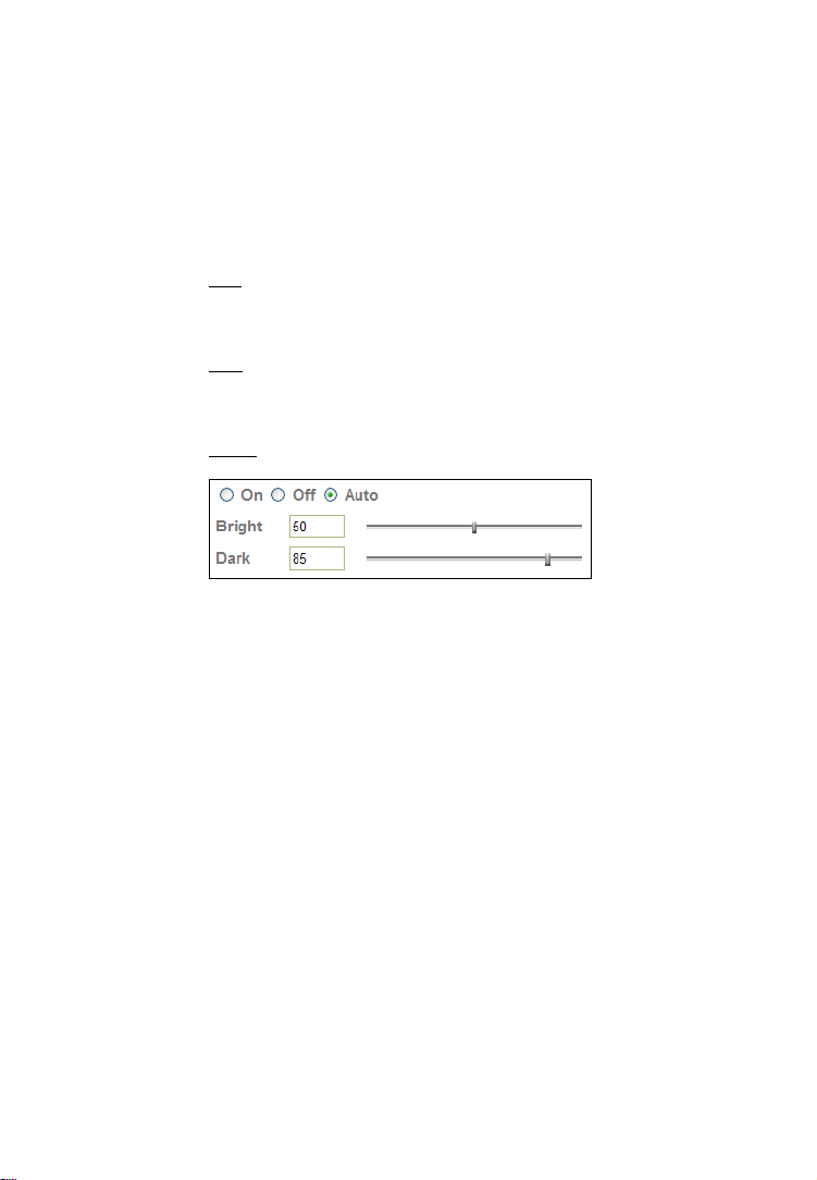
IR: Cameras that are equipped with infrared allow the control of
the camera’s function at night.
On:
Activates the night vision mode. The I R cut filter is
removed when this option is enabled. The IR LEDs are
activated and the image turns black and white.
Off:
The IR functionality is deactivated and the camera will
always send color images. At night, however, the camera will
not be able to capture proper video.
Auto:
In this mode the camera automatically engages the
night vision mode when a certain level of light is reached. The
“Bright” value defines the threshold at which the camera
switches IR mode to color mode. The “Dark” value does the
opposite. It tells the camera at which light level to remove the
IR cut filter and activate the IR LEDs.
The image below illustrates the difference between the IR
mode being on and off.
Left: IR = “Off.” Right: IR = “On” or “Auto”
Note: Standard cameras do not display this parameter; they
display a parameter called night mode, which can be set to
“Auto” or “Off.” Auto means that the camera increases the
shutter time to ¼ second, creating a longer exposure ti me,
which allows the camera to capture images even in low light
conditions. When set to “Off,” the camera will not adjust the
shutter time and the resulting images are darker.
Overlay: Activate text overlay in
order to display the date
and time information on
the live image of the
camera, along with an
alias name for the camera.
When these options are
activated, the live video
shows the information in
the specified position, as
shown to the right.
- 55 -
Page 56

When privacy masking is activated, a new option appears on
the screen that allows you to censor (black out) an area in the
image you don’t wish the camera to capture.
Use your mouse in order to resize the box and move it into
the desired position on the live video. Privacy masking is an
important function designed to protect the people’s right for
privacy.
Example 1: The camera is installed in your home: e.g.,
overlooking your driveway. In the background is the
neighbor’s house, which you have no intention of monitoring.
It would illegal in some cases for you to do so. To resolve this
problem, you can activate a privacy zone over your neighbor’s
house.
Example 2: The camera is installed in your company; for
example, overlooking the warehouse. In one corner of the
warehouse is the break room, where the employees go for
their lunch breaks. In many countries it is not permitted to
monitor the workers during their break. To comply with laws
and regulations, you can define a privacy mask in the break
area to ensure that this area is not being mo nito red or
recorded by the camera.
Note: Privacy masking can only be set up when using MS
Internet Explorer.
Text overlay is only applied to the MJPEG video stream, if
RTSP mode is set to off.
- 56 -
Page 57

Camera -> MPEG4 -> Computer View (Style 1):
The RTSP and RTP options are for advanced users only. If you are not familiar
with any of these terms, including Multicast and Unicast, there is a good chance
that you do not need these functions of the camera.
RTSP: This is only shown if the RTSP mode is enabled in the general
RTP: The Real-time Transport Protocol (RTP) defines a standardized
Note: If the camera has firmware 1.6.16.05 or newer installed, the RTSP and
RTP options can be found on the Camera -> General page.
settings. When activated, you can define which port you wish
to use for the RTSP protocol. The standard port is 554, but
you can use a different port, if desired.
The viewer authentication controls whether or not a valid user
name and password are required in order to access the
camera live image. For security reasons it is recommended to
set this value to “On” (unlike in t h e screen shot above);
otherwise anyone who knows the network address of your
camera can potentially access the video stream.
packet format for delivering audio and video over the
Internet. This option is only shown if the RTSP mode is
enabled in the general settings.
Unicast Streaming: Define the port range for standard Unicast
streaming here.
Multicast Streaming: Set to “On” to enable it.
- 57 -
Page 58

Once you activate the multicast option, the screen will show
additional options:
Enter the address of your multicast server a long with the
audio and video port. The Time-To-Live value defines how
long multicast traffic will expand across routers. Routers have
a TTL threshold assigned and only datagrams with a TTL
greater than the interface's threshold are forwarded.
Below are additional details regarding the differences between
Unicast and Multicast.
Unicast: For each connected
computer there is a separate
TCP/IP connection. When 20
computers are connected to
the camera, the camera has
to create 20 different
connections, and the camera
has to send out the same
video data to each of the 20 computers. This not only puts a
significant load on the camera, it also creates massive
amounts of data that need to be transferred over the ne twork
to each connected client.
Unicast is still the most common model when using a network
camera, since most times only a recording device (DVR or
NVR) is connected to the camera and perhaps connections
from just a small number of computers.
Multicast: Here the initial stream is sent to the router only,
which creates optimal distribution paths for datagrams sent to
a multicast destination address. Whether one or 300 PCs are
connected to the video stream
does not matter. The
bandwidth and load of the
local camera is unaffected.
Because of this, multicast is
the preferred choice for
broadcast-type applications.
- 58 -
Page 59

MPEG4 Viewer Port:
Image Size: Define the video resolution that the camera send s out by
Frame rate: Select from a range of 5 to 30 fps to define the maximum
Quality: You can control the image quality of the video by selecting
The camera uses two ports, one for regular connections and
one for SSL (HTTPS) encrypted connections. If you are using
the INTELLINET NETWORK SOLUTIONS network camera only
in your local network and do not wish to access the video
remotely over an Internet connection, these values are
unimportant. For remote connections, however, they are
important. The ports entered here need to be programmed
into your router’s port forwarding table to allow incoming
remote connections. Refer to Chapter 7 Remote Access and
Router Setup for details on the port forwarding setup.
selecting the appropriate resolution (160x120, 320x240 and
640x480 pixels) here. The image size has a direct impact on
the amount of network bandwidth required in order to submit
the video stream over the network. The higher the resolution,
the more network bandwidth is used to deliv er the video
stream.
frame rate (frames per second) of the video. The higher the
frame rate, the smoother the video and the more network
bandwidth required to deliver the video stream.
“Fixed Quality” and defining the image quality by selecting
one of the following values “Medium,” “Standard,” “Good,”
“Detailed” and “Excellent.” Or you can choose to specify the
bit rate of the video the camera must not ex ceed. When you
set the quality to “Auto,” the camera varies the image quality
automatically based on the connection spee d of the connected
client.
- 59 -
Page 60

Camera -> MPEG4 -> Mobile View (Style 1):
The network camera has the ability to
send out a low-resolution video stream
that is ideal for remote viewing via a
mobile phone.
The camera supports 3GPP and 2.5
WAP for older phones.
The options are the same as the
computer view, except that the image
size is fixed to 160x120 pixels, and the
frame rate and quality settings are
much lower.
Camera -> MJPEG (Style 1):
In addition to MPEG4, the network camera can also send out a Motion-JPEG
video stream. While Motion-JPEG has a much larger network footprint than
MPEG4 or H.264, and therefore requires more network bandwidth to submit the
same video information, it is still widely used in the video surveillance
environment. As seen before, you can define the individual ports that the video
stream uses, along with the image size, frame rate and quality.
Note: When RTSP is activated, Mot io n-JPEG cannot be used at the same time
and the screen options are disabled.
This concludes the camera category options for all MPEG4/Mo tion-JPEG network
cameras. The following section describes the options for the H.264 Megapixel
camera models.
- 60 -
Page 61

Camera -> General (Style 2):
RTSP: Specify the RTSP port here. The default port is 554.
RTP: Define the RTP port range here.
Image Rotated: Choose from one of the following options: “None,” “Mirror,”
Audio Codec: Here you ca n define which audio codec the camera uses.
Audio mode: There are two choices here. “Full Duplex” means that the
“Flip” and “Mirror + Flip.” With this function you can mirror
the image vertically, horizontally or both. The default value is
“None.”
There are four choices:
g.711 u-law / g.711 a-law:
Modulation (PCM), is a very commonly used waveform codec
that generates a 64 kbps bit rate.
AMR Audio:
by 3GPP in October 1998 and is now widely used in GSM and
UMTS. AMR Audio uses less bandwidth than g.711 audio.
When AMR is selected, you can specify the bit rate between
4.75 and 12.2 Kbps.
Off:
Disable the audio function in the camera.
camera can send and receive audio simultaneously. “Half
Duplex” means the camera can send out audio to the
connected client PC, but can’t receive audio from it.
AMR was adopted as the standard speech codec
G.711, also known as Pulse Code
- 61 -
Page 62
Video Clip Format:
IR Threshold: If your camera is equipped with Infrared, you can define the
The camera has the ability to send out shor t video clips to an
FTP server, via e-mail or to a local SMB network storage
device. Find more about that in the advanced section. Here
you define the format of the video clip. You can choose
between H.264 and MPEG4. Each of these streams can be
defined individually in terms of video resolution and quality in
the corresponding menus.
behavior of the camera under different light conditions.
On:
Activates night vision permanently. The camera removes
the IR cut filter and activates the IR LEDs. The resulting
image is black and white, but the camera can capture video
even in complete darkness.
Off:
Permanently deactivates the night vision mode. Even at
night or under poor light conditions the camera will continue
to send color video. The disadvantage is that the video may
not contain any visual details due to the lo w light levels.
Auto:
The camera automatically activates the night vision
mode based on the Bright and Dark parameters.
The “Bright” value defines the threshold at which the camera
switches from IR mode to color mode.
The “Dark” value does the opposite. It tells the camera at
which light level to remove the IR cut filter and activate the IR
LEDs.
The Bright parameter defines the time when the camera goes
into color mode in the morning while the Dark parameter tells
the camera when to engage the night vision mode at night.
Overlay: You can activate a text overlay on the live image. This can be
either a date and time stamp along with the camera’s alias, or
it can be a privacy mask. Refer to the overlay section in style
1 for more detailed information on the setup.
Note: The text overlay is only active for H.264 and MPEG4 video.
- 62 -
Page 63

Camera -> H.264/MPEG4/MJPEG (Style 2):
The network camera is a multi-stream device. It can send out H.264, MPEG4
and Motion-JPEG video. Each stream can be configured independently
concerning video resolution, video quality and more. The individual setup pages
have the same parameters.
Viewer authentication: When activated, a user name and p a ssword is required
in order to access the video stream.
Multicast streaming: Enable this option to utilize multicast streaming. When
activated, you need to provide additional information such as
the multicast address, audio and video port and the Time-ToLive parameter. More information on Multicast streaming can
be found in section “Camera -> MPEG4 -> Computer View
(Style 1).”
Image Size: Define the video resolution that the camera send s out by
selecting the appropriate resolution (160x120, 320x240,
640x480, 1280x720 or 1280x1024 pixel). The image size has
a direct impact on the amount of network bandwidth required
in order to submit the video stream over the network. The
higher the resolution, the more network bandwidth is used to
deliver the video stream.
Frame rate: Select from a range of 1 to 30 fps to define the maximum
frame rate (frames per second) of the video. Higher frame
rates yield smoother video, but generate more network
bandwidth.
- 63 -
Page 64

Quality: This allows you to control the image quality of the video.
IP Interval: This parameter defines the I-Frame interval. MPEG4 video
Camera -> 3GPP (Style 2):
Auto:
The camera automatically adjusts the quality based on
the connection speed of the connected client .
Fixed quality:
Fixed bitrate:
stream from 64 kbps (low quality) to 6 Mbps (high quality).
Note: Fixed bitrate is not available for the MJPEG stream.
streams consist of a series of frames. An I-Frame is an Intracoded picture; in effect, a fully specified picture, like a
conventional static image file. A P-frame (predicted picture)
holds only the changes in the image fr om the previous frame.
The IP interval defines how many P-Frames are sent out by
the camera before another I-Frame is sent.
Auto:
The camera automatically adjusts this value (defa ult).
5 – 120:
which the camera sends another I-Frame. The lower the
number, the more I-Frames are sent out resulting in a larger
video as far as bandwidth is concerned. Values between 5 and
20 typically yield good results.
Select the quality from medium to excellent.
Define the maximum network bandwidth for this
The number specifies the number of frames, after
These are the settings for 3GPP mobile phone streaming. The options are
similar to those of H.264, MPEG4 and MJPEG except that some values are much
lower than for the other streams to make the stream suitable for mobile phone
streaming.
- 64 -
Page 65

Camera -> Advance (Style 2):
White Balance: Select the value that best represents the installation
Lighting: If the camera is installed indoors, select either 50 or 60 Hz,
Exposure mode: Exposure mode controls the behavior of the shutter, which is
environment of the camera, or leave it on auto to let the
camera do the adjustment automatically for you.
depending on the power grid frequency in your country.
Select Outdoor, if the camera is installed outside, or pointing
outside. The automatic mode can also be used, but best
results are ensured by manually specifying the correct value
for your location.
used to control the brightness of the video.
Auto:
The camera controls the shutter speed automatica lly.
As light levels decrease, the camera keeps the shutter open
longer and vice versa.
Auto (fast shutter):
moving objects (e.g., cars) are captured by the camera. Th e
shorter shutter time ensures that the moving object remains
sharp.
Manual:
time the camera keeps the shutter open. This is useful if you
want to instruct the camera to keep the shutter open for a
relatively long time in order to be able to capture video in
poor light conditions. Values range from ¼ sec. to 1/120
seconds. With the gain value you can also adjust the
exposure time. This feature is not suitable if the camera
captures outdoor video and typically, you do not need to
change the exposure mode to manual.
When this is selected, you can manually specify the
This mode provides better results when
- 65 -
Page 66

Camera -> Playback (Style 2):
The INTELLINET NETWORK SOLUTIONS Network Camera is equipped with an
integrated video player. With this player you can play back videos that you
have recorded with the camera; e.g., by using the record function on the live
video page. The video player can also playback other video sources, if the
necessary video codecs are installed on your computer.
The controls consist of the typical array of buttons you find in most common
media players; e.g., play, pause, stop and open, fast forward and rewind, time
display, volume and full screen controls.
Note: The video player can only be used with MS Internet Explorer. Other Web
browsers do not support this function.
- 66 -
Page 67

Camera -> Network -> Information:
On this page you can define the network settings of the camera. By default the
camera is set up to automatically obtain the ne cessary IP information from the
DHCP server (e.g., the router) in your network. You can, however, set up the IP
address and related settings manually.
MAC address: MAC address stands for Media Access Co ntrol address. This is
Obtain an IP address automatically (DHCP): This is the default setting. In this
Use the following IP address: Activate this option in order to assign a static IP
Use the following DNS server address: When you disable DHCP, you also need
HTTP port number: The default value is 80 and normally there is no need to
the unique hardware address of the camera’s network
interface.
mode the camera obtains the IP information from the DHCP
server in your network.
address to the camera. You need to enter a valid IP address,
subnet mask and default gateway address in the
corresponding fields.
to provide the camera with valid DNS settings. The Primary
DNS server must be filled out. It is often the same IP address
as the Gateway address.
change it. If you decide to change the http port to a different
value; e.g., 1024, you need to do two things:
1. After saving the settings you need to reboot the camera via
the System -> Initialize menu.
2. After the reboot is completed you need to connect to the
camera using the URL http://camera_ip:portnumber.
- 67 -
Page 68

Camera -> Network -> PPPoE:
PPPoE is the most common form of connection for DSL-based Internet service.
You can use this function to connect the camera directly to a DSL modem. A
common application for this is where the network camera is installed in a
remote location where no network is present. In the location is a DSL Internet
connection (DSL modem), but no router or any other network infrastructure.
You can connect the camera to the DSL modem and enter your DSL account
information in the fields belo w.
IP address: Displays the current IP address obtained from the Internet
Service Provider (ISP). It displays 0.0.0.0 if the camera is not
connected to the Internet via PPPoE.
User ID: Enter the user ID for your DSL service here. The user ID has
been given to you by your ISP.
Password: The password for the DSL account goes here. Re-type the
password in the field below.
DNS Server: Typically, your ISP will send DNS Server information to th e
camera when it connects. Some ISPs, however, require
entering specific DNS servers manually. In that case you c an
activate the option “Use the following DNS server address”
and enter the primary and secondary DNS servers in the
fields below (not shown on the screen shot).
- 68 -
Page 69

Camera -> Network -> DDNS:
If you are not planning on connecting to the network camera over a remote
connection, but only in your local network, you can skip this section.
Dynamic DNS is a network service that provides the capability for a networked
device, such as a router or computer system, to notify a domain name server to
change, in real time (ad-hoc) the active DNS configuration of its configured
host names, addresses or other information stored in DNS.
In simpler terms: Users of private Internet services are often faced with a
problem: The ISP typically changes the IP address assigned to the user based
on a time interval. This may be as often as once every 24 hours or as seldom
as once every 30 days. For the average user this is not a problem. However, if
you want to be able to connect to the local camera (e.g., in your house) fr om a
remote location (e.g., the office), you need to know under which Internet
address the camera can be reached. However, you don’t know what the current
Internet IP address is. So you are beginning to see the problem.
DDNS solves this problem by allow ing y ou to create a domain name for your
home network, which you can always use to access the camera. To use the
DDNS function, you will need to do the following two things.
1. Create a DDNS hostname with a DDNS service provider
2. Set up a DDNS client in the home network that contacts the DDNS service
provider and updates the IP information.
The INTELLINET NETWORK SOLUTIONS network camera supports three
different DDNS providers: DYNDNS.ORG, DHS.ORG and TZO.COM. Of the three,
as of February 2010 only dyndns.org is a free service (be aware that this may
change). This user manual therefore focuses on the dyndns.org service.
You first need to register and create an
account on www.dyndns.org.
1. Connect to http://www.dyndns.org and click “Create Account.”
2. Follow the step-by-step instru ctions on the DYNDNS screens, inputting all
information requested.
3. Log in with the new account and go to Account → My Hosts → Add
Host Services.
4. Enter the domain in the Hostname field and select a sub-domain from the
drop-down menu. Follow the check-out procedure.
5. After entering the information, check your service and make sure that the
DDNS domain name is listed under Account → My Hosts.
6. On the camera’s DDNS screen, fill in the fields and reboot the camera (see
next page).
- 69 -
Page 70

Note: If the router in your home network is equipped with a DDNS client, we
recommend using the router instead of the camera. Most SOHO routers are
equipped with a DDNS client and since the router is in direct control of handling
the Internet connection, it’s the device best suited for the DDNS task.
Server Name: Select the DDNS provider of your choice. In our example we
use www.dyndns.org.
User ID: Enter the same user name here that you use to log in to your
account settings on www.dyndns.org. Do not enter your DSL
user account information here.
Password: Enter the password for your dyndns.org user account here.
Re-type the password in the field below.
Host name: You need to enter the full host name that you have created in
your dyndns.org account here.
Click OK to save the settings. Reboot the camera via the System -> Initialize
menu to activate the DDNS settings.
After a reboot you may need to wait for a few minutes before you can access
the camera with the new domain name.
- 70 -
Page 71

Camera -> Network -> UPnP:
UPnP stands for Universal Plug and Play. A UPnP-enabled
device, such as your network camera, announces its
presence in the local network to other computers that
support UPnP as well. The operating systems Windows
XP, Windows Vista and Windows 7 support UPnP. When
the network camera is connected to th e network,
Windows will alert the computer user of the presence of
the new device (a new icon will be added to your My
Network Places folder) and lets the user co nnect to the
device instantaneously.
Furthermore, UPnP has the ability to instruct the router
or firewall to open certain ports, so that a party from the
outside world can contact a device on the local network,
such as the network camera.
UPnP port forwarding is not supported by all routers,
however. So, depending on your router or firewall, you
may or may not be able use this function. Also, opening
ports in any router or firewall increases the risk of an intruder successfully
breaking in to your network. UPnP automates thi s task and leaves it to the
devices to negotiate which ports to open. Since this is done without any form of
authentication, enabling UPnP port forwarding in your router is not necessarily
a good idea in a security-sensitive environment. You can always open individual
ports in your router or firewall manually. See Chapter 7 Remote Access and
Router Setup.
In the camera UPnP is enabled by default. UPnP port forwarding is disabled by
default. When you enable UPnP port forwarding, the screen will reveal
additional options. These are the ports the camera will instruct the router to
open. Depending on the camera model, you may see different ports. The new
H.264 Megapixel cameras have a simpler port model and require fewer ports
than the other models. Normally there is no need to change any of these ports,
unless you know that a port is already in use by a different device or
application.
- 71 -
Page 72

Camera -> Network -> Bonjour:
Bonjour is a service that, just like UPnP, helps to find the network camera on
the network. Bonjour is available for Windows, but is more commonly used for
MacOS. Refer to section “4.1.2 MacOS” for additional information on the usage.
Bonjour: On:
Off:
Device name: Enter the name of your camera here. This is the name the
Enables the service (on by default).
Disables the service.
Bonjour service will display. If you have more than one
camera installed in your network, this is an easy way to
differentiate among the cameras.
Camera -> Network -> IP Notification:
The camera can inform the user via e-mail about the IP address it is set to. If
the camera is set up with a dynamic IP address (default), then the camera IP
address may change from time to time as the DHCP server (router) may assign
a new IP address when the so-called Lease Time has expired. If the camera is
connected directly to a cable or DSL modem, the IP address also changes
frequently (or infrequently, depending on your ISP).
In both cases it is useful to have the camera send you an e-mail that includes
the current IP settings.
In order to use IP Notification, you need to set up e-mail related parameters. If
you do not know this information, you need to contact your network
administrator.
- 72 -
Page 73

Notify type: Select which type of connection (DHCP, Static IP or PPPoE)
should be observed by the IP notification function. For
example, if you uncheck Static IP and your camera is set up
with a static IP address, you will not receive an e-mail
notification.
SMTP server name: Enter the domain name of the Sendmail server (outgoing e-
mail server) here.
SMTP server port: Port 25 is the standard port for SMTP connections. If your
SMTP server uses a different port, you can enter it here.
Authentication: Most SMTP servers require user authentication to prevent
abuse. Set this to On to enable authentication. Then select
the type of authentication. If you are not sure which value
is correct, contact your network administrator to find out.
When selecting POP before SMTP you need to specify the
POP server name (not shown on screen shot).
You also need to provide the SMTP user name and
password. Typically, these are the same values you use in
your e-mail program profile.
Recipient e-Mail address:
Enter the e-mail address to which the cam era sends the email.
Administrator e-Mail address:
This is the sender e-mail address that th e camera uses.
Subject: You can define the subject of the e-mail here.
Message: You can customize the message body of the e-mail here.
Click “Help” for more information on the parameters.
- 73 -
Page 74

Camera -> Network -> Wireless:
If your network camera supports wireless, you can configure the related
settings on this page. The camera has the abil ity to find the wireless network
and allows you to quickly enter the correct encryption key.
Status of wireless networks:
ESSID: This is the wireless network name the camera wil l co nnect to.
Authentication: The camera has selected the correct authentication mode. If
Encryption: As with the authentication, the camera has automatically
All wireless networks in range are shown here. Select the
correct wireless network by highlig hting it. Once selected, you
will see that some of the fields automatically populate.
you configure the wireless network manually, you will need to
select the correct authentication type.
populated these fields for you.
- 74 -
Page 75

Passphrase: Enter the password for your wireless network here. Repeat
The wireless interface has its own IP settings. These are independent from the
regular settings (Network -> Information) and must be configured separately.
Obtain an IP address automatically (DHCP):
Use the following IP address:
Use the following DNS server address:
Note: Do not set up the Network interfaces (LAN and WLAN) with the same
static IP address.
Camera -> Network -> Messenger:
The INTELLINET NETWORK SOLUTIONS network camera has a unique feature
that allows it to act as a Web camera for Windows Live Messenger.
the password in the field below.
Enable this and the camera will obtain the IP information from
the DHCP server in your network.
If you activate this option, you need to enter the IP-related
values (IP address, subnet mask, default gateway) in the
corresponding fields below.
If you enter the IP settings manually, you also need to key in
proper DNS server information. The primary DNS server is
mandatory. The secondary DNS server is used as a backup.
- 75 -
Page 76

In order to use the function, you need to perform two steps.
First, you need to set up a new account for the Windows Live / Hotmail service.
This account will be used by your network camera. You cannot use your
existing Messenger account for the camera. Note the user name and password
for the new account and proceed to the configuration of the network camera.
Login Account: Enter the user name of the newly created account here.
Password: The password of the new account goes here. As always,
repeat the password in the field below.
Alias: Enter a descriptive alias in this field; e.g., “mycamera.”
Port range: This defines which TCP/IP ports the camera uses to send out
video. These ports need to be opened in the firewall. See
chapter 7 Remote Access and Router Setup for details.
Video mode: Here you define which video settings apply to the video
stream. Mobile view uses the 3GPP settings. Computer view
uses the regular settings (larger video is transmitted).
IP Notification: When this is activated, the camera will announce its IP
settings to any client via Live Messenger.
- 76 -
Page 77

Privacy: Set this to “On” to only allow people in the allow list to be
User: In order to add a user to the allow list, type in the user’s e-
Allow list: All users that can access the camera via Live Messenger are
When you add a user to the allow list, the
camera will send a friend request notification to
the Messenger user. If the request is granted,
the user can then connect to the camera. To do
that, the following steps are required.
1. Locate the camera in your buddy list. Then
right-click the contact and select “Send an
instant message.”
2. When done, the regular chat window will open. To
the left of the messenger contact image you can find
a little Web cam icon. Click it and select “View this
contact’s webcam.”
3. The connection will then be established. You will see the following messages
in the message window:
You have invited Camera to start sending Webcam. Please wait for a response
or Cancel (Alt+Q) the pending invitation.
Camera has accepted your invitation to start sending Webcam.
It will take a few moments for the video to appear on the screen.
Note: If the video cannot be seen, a firewall may be blocking the video. The
firewall can be on the Live Messenger user side, or it is possible that the
camera is installed behind a firewall and the required ports are not properly set
up in the port forwarding table of the router. See “Remote Access – Port
Forwarding” for details.
able to connect to the camera and view the video.
mail address here and click on “Add.” If you wish to remove a
user from the allow list, select the user from the allow list
field below, then click Remove.
listed here.
- 77 -
Page 78

Camera -> Security -> Account:
The INTELLINET NETWORK SOLUTIONS network camera allows the creation of
different user accounts with different levels of access to the camera. There are
three main user levels. The Viewer account only allows viewing the live video
page of the camera. The Operator account allows viewing the live video as well
as changing the image setup settings, such as brightness, contrast, etc. Only
the Administrator account has full access to all camera settings, including the
Settings menu.
You can define up to nine different user accounts. The user name and password
must be between 4 and 16 characters in length. For each account you can also
specify the viewer mode (Administrator, Operator or Viewer).
Viewer authentication:
If this is enabled, a valid user name and password is required
in order to connect to the camera.
If you set this option to “Off,” a new option appears on the
screen (not shown in the screen shot above), that allows you
to set the viewer mode to
a) Viewer (no password required for viewing, but password is
required for any other function)
b) Operator (no password is required, except if the user
wishes to access the settings menu)
c) Administrator (no password is required for any of the
camera’s settings and functions). This setting is not
recommended because you allow any user full access to the
camera.
- 78 -
Page 79

Camera -> Security -> HTTPS:
Secure Sockets Layer (SSL) is a cryptographic protocol that provides security
for communications over networks such as the Internet.
HTTPS is a URI scheme used to indicate a secure HTTP co nnection (SSL
encrypted). It is syntactically similar to the http:// scheme that is normally
used for accessing resources using HTTP. The differences are that SSLencrypted connections always begin with ht tps:// instead of http://. HTTPS
connections use TCP port 443 by default, compared to standard HTTP
connections, which use port 80.
Create & Install: Click this button to
create a self-signed
certificate. A window
will open in which you
can enter the
information for your
certificate.
Click OK to install the
certificate.
Installed Certificate:
Once the certificate is installed, you can see the details here.
To view the certificate details click on Properties. Click on
Remove to delete it.
HTTPS Connection Policy:
Define for the individual viewer modes, if HTTPS can be used
in order to connect to the camera.
- 79 -
Page 80

Camera -> Security -> IP Filter (only certain models):
The IP filter allows blocking or access to the camera based on the I P address of
the connecting client. This is an additional layer of security, which helps to limit
access to the camera in security-sensitive environments.
IP Filter: Activate this function by setting this option to On.
Allow range: This defines which IP address is allowed to have access to the
camera. Enter the start IP address and end IP Address and
click on Add to add the IP range to the list of allowed IP
addresses.
Allow Range List: All allowed IP addresses are listed here. To remove an entry,
select it from the drop-down list and click Delete.
Deny range: Enter IP addresses here that are not allowed to access the
camera.
Deny Range List: All denied IP addresses are listed here. To remove an entry,
select it from the drop-down list and click Delete.
- 80 -
Page 81

5.2.2 Settings Page – Advanced Settings
The advanced settings menu allows control of the alarm management functions
of your network camera. The camera has the ability to send pictures or videos
to a remote location in case of an alarm or based on a schedule. The alarm
event can be triggered by the camera’s internal motion detection or by an
external alarm sensor.
The H.264 Megapixel cameras add a storage function for local shared network
drivers (Windows SMB or Linux NFS) and audio detection to the range of
features.
Camera -> Advance -> FTP Client -> General:
FTP stands for File Transfer Protocol. FTP is a common method to transfer files
to an FTP server. Such a FTP server can be a local server or it can be your own
Web site. In the general settings you have to specify the details about the FTP
server you wish to use.
- 81 -
Page 82

FTP server name: Enter the address of your FTP server here. Valid entries are
User name: Key in a valid FTP user name here. Make sure that the user
Password: The password for the FTP user account goes here. Repeat
Passive mode: There are two types of FTP connections: Active and passive.
Attached file type: Select Snapshot if you want the camera to upload single
Click OK to save the settings. When done, click on Test to verify the FTP
settings. A popup window will open that informs you whether or not the test
was successful.
either the IP address of the server (format:
111.222.333.444), or the domain name of the server
(format: domainname.com). Invalid entries are
ftp.domainname.com or http://domainname.com.
account you wish to use has read and write privileges on
the FTP server.
the password in the field below.
While the most common method is passive FTP, your server
may be set up to only accept FTP conn ections that utilize
active FTP. The correct value here depends on the FTP
server setup. When in doubt, we recommend using passive
mode, trying active mode only if you experience problems
connecting to the FTP server.
images (JPEG format). Selecting Video clip instructs the
camera to upload short video clips in length of max. 5
seconds. This option is only available in certain models.
The FTP settings are correct and the test has succeeded.
- 82 -
Page 83

Camera -> Advance -> FTP Client -> Alarm sending:
On this screen you activate the alarm-triggered FTP upload. In this mode, the
camera only uploads an image or a short video clip to the FTP server if an
alarm condition (motion, audio alarm, network link down or external alarm
input) has occurred.
Remote path: Key in the folder name on the FTP server in which the
Image file name: Enter the image file name here. This value is the first part
Suffix: Select the type of information you wish to append to the
Alarm: Motion Detection:
camera uploads the files. The folder is a sub-directory of
the home (root) folder of the FTP user account. Leave this
value empty and the camera will upload the files i nto the
home directory of the FTP user.
of the file name.
image name. Possible values are Date Time or Sequence
number.
Activate this option if the FTP upload
should be triggered by a motion detection event. The
button to the right leads to the motion d etection setup
screen, which is described later in this chapter.
- 83 -
Page 84

Audio Detection: Activate this option if you want the
camera to monitor the audio levels picked up by the
camera’s internal microphone, or by the external
microphone, should you have one connected. The button to
the right opens the audio detection setup screen.
Network Link Down (only H.264 cameras):
In case the network connection breaks down, the camera
keeps the last 10 seconds in its internal buffer. When the
network connection is re-established, the camera s ends out
the information.
Alarm input:
device to the camera’s digital input port, you can activate it
here and define the settings by clicking on the button to the
right.
Effective Period: Choose between “Always” and “Schedule”. Always means
that the alarm sending function is act iv a ted all the time,
regardless of time and day. Schedule allows activating this
function at a specific time. A common application for the
scheduled alarm sending is the following scenario:
A camera is installed in an office. The regular working hours
are from 9 am to 6 pm. Some workers often work late and
leave the building at 7:30 pm. In a situat ion like this, you
can activate the camera’s alarm sending at 7:40 pm and
leave it activated until 8:45 am to avoid get ting a lot of
unnecessary files triggered by the workers moving around
in front of the camera. The Schedule button allows the
setup of individual activation and deactivation times for
each day of the week.
If you have connected an external alarm
- 84 -
Page 85

Camera -> Advance -> FTP Client -> Periodical sending:
Certain applications call for the periodic uploading of an image to an FTP server.
A typical application is
when you want to display
a live image of your
camera on your Web site,
which, for example,
refreshes itself every 60
seconds. The image on
the right illustrates such a
setup.
The settings are similar to the alarm sending page. You can specify a remote
path, the image file name and the suffix. In our example the suffix should be
set to “None,” or the Web page would not be able to display the image due to
the ever-changing file name. The interval defines how often the image is
uploaded. As before, you can enable the function all the time or based on a
schedule.
- 85 -
Page 86

Camera -> Advance -> SMTP -> General:
In addition to FTP uploads, the network camera can also send images or short
video clips via e-mail. Simple Mail Transfer Protocol (SMTP) is an Internet
standard for e-mail delivery across Internet Protocol (IP) networks. Whenever
you send an e-mail from your computer, SMTP is the protocol that makes sure
it reaches its destination. The network camera uses the same mechanisms and
effectively acts like your standard e-mail client; e.g., Mozilla Thunderbird,
Opera Mail or Outlook, with the exception that the camera can only send e-mail
but not receive it.
In order to use the e-mail function of the camera, you need to provide the
information shown below. If you don’t know these values, contact your ISP
(Internet service provider) or your network administrator.
SMTP server name: This is the address of the outgoing mail server, the
sendmail server or SMTP server.
SMTP server port: The default port for e-mail delivery is 25. However , in case
your SMTP server uses a different port; e.g., as an antispam measure, you can change the port here.
SSL: Some e-mail servers only accept connections made via SSL
(Secure Socket Layer). If this is the case with your SMTP
server, you need to check this option. Otherwise, you can
leave it unchecked.
- 86 -
Page 87

Authentication: Most SMTP servers require that the client authenticates
SMTP:
Recipient e-Mail address:
Administrator e-Mail address:
Attached file type: Select snapshot if you want the camera to send single
Subject: Define the subject of the e-mail message here.
Message: Enter the message body of the e-mail.
Click “OK” to save the settings. When
done, click “Test” to verify the e-mail
settings. A popup window will open
that informs you whether or not the
test was successful.
properly prior to accepting e-mail delivery. Unless your
SMTP server does not require authentication, this option
should be enabled.
When this option is activated, the camera will submit
a user name and password to the SMTP server for
authentication. Type in a valid user name and password in
the fields below.
POP before SMTP:
authentication method, you also need to provide the
address of the incoming e-mail (POP) server.
Enter the e-mail address where you want the camera to
send the videos and pictures.
This is the e-mail address that the camera uses a s its
“from” address. You should fill out this field (e.g.,
mycamera@mydomain.com), because some SMTP servers
will not deliver e-mail from clients that have no “from”
address specified.
images (JPEG format). Selecting “video clip” instructs the
camera to send short video clips in length of max. 5
seconds. This option is only available in certain models.
If your SMTP server uses this
- 87 -
Page 88

Camera -> Advance -> SMTP -> Alarm Sending:
On this page you can link the trigger condition to
the e-mail delivery function of the camera. The
options are identical to those of the FTP Alarm
Sending page.
Camera -> Advance -> SMTP -> Periodical sending:
This page allows setting up the INTELLINET
NETWORK SOLUTIONS network camera to send an
e-mail based on a time interval from 30 minutes to
24 hours. The setup is identical to that of the FTP
Periodical Sending function.
Camera -> Advance -> Storage-> General (only certain
models):
The H.264 Megapixel cameras support saving files on a local network storage
location. This function is ideal for the recording of larger files (e.g., 24/7
recordings) and it takes advantage of existing NAS (Network Attached Storage)
shares in your network. The two most common network file-sharing protocols
are Server Message Block (SMB), which is primarily used by Windows, and the
Network File System (NFS) that was originally developed by Sun Microsy stems
in 1984.
- 88 -
Page 89

Protocol: Select the correct protocol here. If you want the camera to
store the data on a shared Windows drive or folder, you
should select “SMB”. If you have a NAS device in your
network, the correct value depends on which protocol (SMB
or NFS) is supported by the NAS. In most cases both
protocols should be supported. If you are in a Unix/Linux
environment, your choice would be NFS.
Network storage location:
Enter the URL for the local storage here.
Workgroup: Key in the workgroup that corresponds to your network.
Common values are WORKGROUP or MSHOME, but
ultimately it depends on the settings in your network.
User name: Enter the user name for the shared network drive or folder
here. Make sure that the user account has read and write
permissions on the network drive or folder.
Password: The password of the account goes here. As always, repeat
the password in the field below.
Click “OK” to save the settings. When done, click “Test” to verify the storage
settings. A popup window will open that informs you whether or not the test
was successful.
- 89 -
Page 90

Camera -> Advance -> Storage -> Alarm Sending:
On this page you can define which alarm trigger
event is linked to the storage recording function. The
options on this page are identical to those on the FTP
and SMTP Alarm Sending page, with one exception.
The Recording time allows you to specify the length of the video c lip. You can
set the recording time between 5 and 60 seconds.
Camera -> Advance -> Storage -> Periodical Sending:
Just as with FTP and SMTP, there is a periodic saving function integrated for the
network storage. The nature of SMB- and NFS-based file saving allows the
camera to save much larger files, making this function ideal for permanent
archive recordings.
Most of the parameters are identical to FTP and SMTP periodic recording. The
file size value defines the size of the individual recordings (ranging from 1 to 50
MB). Cyclic size represents the maximum combined disk space of all recordings.
When this value is reached, the camera will start overwriting existing
recordings, starting with the oldest one. The default cyclic size is 1024 MB (1
Gigabyte). The maximum value is 1024000 MB (1 Terabyte).
- 90 -
Page 91

Camera -> Advance -> HTTP Event -> General:
HTTP Event represents the most advanced form of the event trigger actions.
When this function is enabled, the camera will not upload or send any video
clips to a remote location, but will instead send an HTTP request to a specified
URL.
What is the purpose of this function? Here are two examples:
1. Some of the more sophisticated third-party video monitoring and
surveillance applications have the ability to start a recording when the camera
calls a certain URL on the video surveillance server. Here, the surveillance
software does not constantly monitor the live video stream to determine
whether or not a motion event has occurred, but it listens to the HTTP events
that are sent by the camera. The advantage of this setup is that the network
load is kept to a minimum because a connection between the camera and the
surveillance software is only established in the event that an alarm event has
occurred. If you think of larger installations involving many cameras, you can
see what a difference this can make.
2. The HTTP event can be used to trigger a script on a Web server, i.e., a PHP
script that logs events in a database so that a record is kept of all events. The
same script could also be retrieving images from the camera when the event
happens. You can also instruct the camera to add a unique parameter to the
HTTP request, based on the type of event that has occurred (see HTTP Event ->
Alarm Sending).
The possibilities for this function are endless and the implementation in the
network camera provides great flex ibility.
- 91 -
Page 92

URL: The basic script URL goes here. Note: You need to ent er the
Port: Standard HTTP requests are made on port 80, but if your
User ID: If the script URL is password protected, you need to enter a
Password: Enter the password here if the script URL requires
Proxy Server: The proxy server parameters are all optional and only need
Camera -> Advance -> HTTP Event -> Alarm Sending:
URL without any leading http://.
application requires a different port, you can define it here.
valid User ID in this field.
authentication.
to be used in case the camera cannot directly connect to
the script URL, but only via a proxy server.
- 92 -
Page 93

Alarm: Motion Detection: Activate this option if you want the mot ion
Parameter & Message:
Effective Period:
Below are two examples that show what kind of URLs the camera could be
calling in case of an alarm. The examples are based on the information shown
in the screen shot, but you can define completely different values.
1. The camera has detected a motion.
URL: http://myserver:80/script_url?event =motion
2. The external alarm (e.g., an IR motion sensor) is in the alert state.
URL: http://myserver:80/scri pt_url?event=extalarm
detection trigger event to be linked to the HTTP event.
Audio Detection:
Megapixel cameras. It allows linking o f the audio detection event
to the HTTP event.
Network Link Down:
Megapixel cameras. In case the network connection break s down,
the camera keeps the last 10 seconds in its internal buffer. When
the network connection is re-established, the camera then sends
out the information.
Alarm input:
camera, you can activate this trigger for the HTTP event.
For each of the events, you can define an optional parameter and
parameter value, as shown in the screen shot above. This can be
used so that the script called by the camera can differentiate
between the various types of events to perform different kinds of
actions. The message allows you to define a description for the
event.
As with the other event types, you can activate the HTTP event all
the time (value = always), or based on a schedule.
This parameter is only available on the H.264
This parameter is only available on the H.264
If an external alarm sensor is connected to the
- 93 -
Page 94

Camera -> Advance -> Alarm Output:
If your Network Camera features a terminal block connector, you can connect
an external alarm device to it. The camera can send power to the device when
a trigger event has occurred.
Digital output: Sets the digital output to either high or low in case of an
alarm event. Refer to page 21.
Trigger condition: Set the value to “Timer” if you want the action to occur
based on a schedule. If you set the value to “Alarm,” you
can define which of the alarm events (Motion Dete ction,
Audio Detection [some models], Network link down [some
models] and Alarm input) can trigger the alarm output
action.
Alarm duration: You can define how long the camera activates the output
port. Set it to 60 seconds and the camera will send out
12 V current for a period of one minute.
Effective Period: As with the other event types, you can activate the alarm
output event based on a schedule, or the entire time.
- 94 -
Page 95
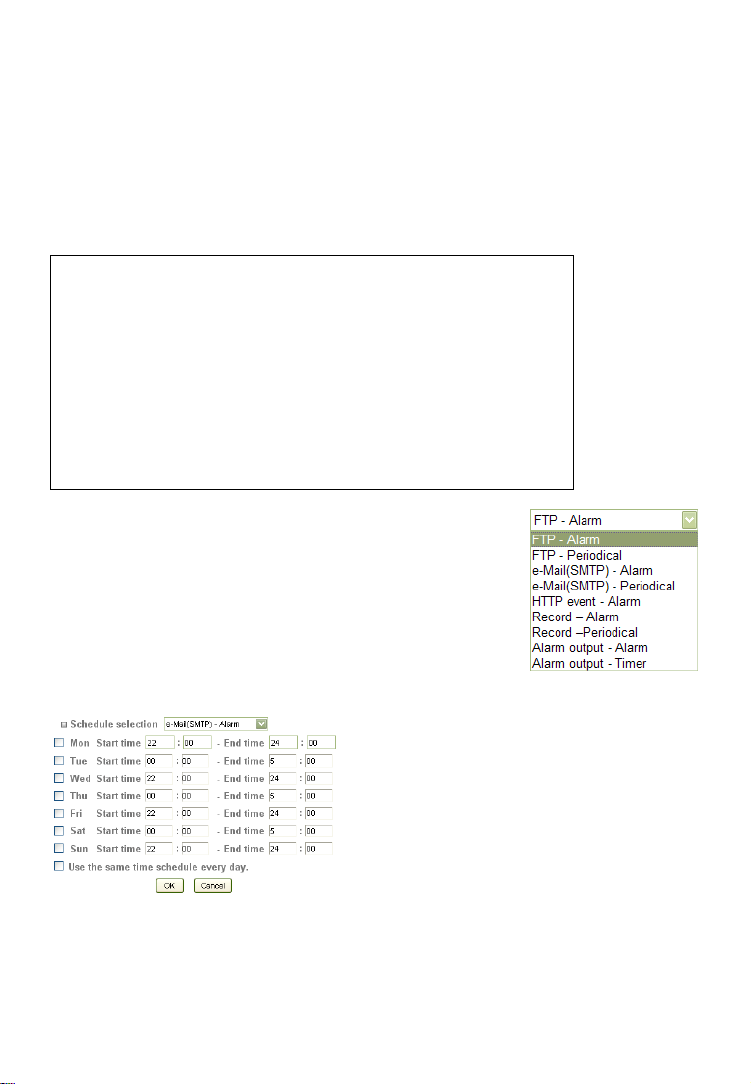
Camera -> Advance -> Schedule:
The Network Camera supports event trigger actions that can be based on a
schedule. This can be used, as an example, to only activate motion detection
between 9 pm and 6 am during business days and around the clock on the
weekends. You can set up individual schedules for each event type, so that
motion detection is activated between 7 pm and 7 am, but audio detection is
only activated between 10 pm and 4 am.
Depending on your camera model, the screen layout will vary slightly.
First you need to select the type of event from the dropdown list. The drop-down list contains the values shown
on the right. Select a start and end time and click on
“Add” for the day of the week the schedule is supposed
to be active. As soon as you add a schedule, the timeline
turns red, indicating the active schedule.
If the schedule is the same for every day of the week,
you can activate the option “Use the same time schedule
every day.”
Shown on the left is the alternative
schedule setup page that does not use a
visual timeline. The example shows that
the e-mail alarm is activated betw een 10
pm and 5 am for every day of the week.
- 95 -
Page 96

Camera -> Advance -> Alarm Input:
If your Network Camera features a
terminal block connector (digital I/O)
for the connection of external alarm
sensors, you can set up the trigger
condition for the input on this page.
There are two types of sensors when
it comes to the actual alarm trigger.
One opens the electric circuit in case
of an alarm (digital I/O = low); the
other closes the electric circuit (digital I/O = high).
The camera allows defining of the default state of
the sensor and the alert state.
Digital I/O terminal block connector showing pins
1 and 2 (circled) for the connection of an external
sensor.
Sensor input 1: Select the input sensor from the list. INTELLINET NETWORK
SOLUTIONS network cameras feature only one sensor.
Trigger condition: This value describes the alarm state of the sensor. The
correct value depends on the sensor.
- 96 -
Page 97

Camera -> Advance -> Alarm Buffer (only certain models):
On this page you can define the size of the alarm image buffer. The camera
holds a maximum of 10 seconds of video in the buffer. When an event occurs
and the camera uploads a video clip to an FTP server or sends it via e-mail, the
length of the video is determined by the buffer settings on this page. You won’t
need to make any changes unless you want to make the image buffer smaller.
Note: The pre-alarm buffer is only used for the Network Link Down alarm
event. The other events (motion detection, audio detection and alarm input)
only use the port-alarm buffer. That means that if the camera uploads a video
in response to a motion alarm, the video will only be the length of the postalarm buffer settings.
Recording capacity: The total buffer capacity is shown here for both pre- and
post-alarm periods.
Recording time: You can define the b uffer time for each pre- and post-alarm
period. Values are 0 to 5.
Camera -> Advance -> Motion Detection:
The Network Camera features integrated motion
detection. The camera does a frame-by-frame
comparison and then determines, based on the motion
detection window, sensitivity settings and threshold,
whether or not a motion has occurred.
This motion detection does not use Infrared. It requires a
visible image in order to function.
- 97 -
Page 98

The camera supports three independent motion detection windows that can be
placed and resized individually.
Motion Detection 1, 2, 3: Click to activate the motion detection window. Once
clicked, you will see a rectangle appear on the
screen. Use the mouse to move the rectangle to a
different position or to resize it.
Threshold: The smaller the number, the lower the threshold of
the amount of movement that triggers an alarm. The
more you increase the threshold value the more
movement is required to trigger an alarm.
Sensitivity: The higher this v alue, the more sensitive the mot ion
detection becomes.
Motion is displayed by a green bar (either as shown on top of the detection
window or to the right of the image) and if the detection exceeds the threshold
the color turns red.
Note: Depending on your camera model and firmware version installed, the
screen may have a slightly different layout. Also note that motion detection can
only be set up using MS Internet Explorer as the Web browser.
- 98 -
Page 99

Camera -> Advance -> Audio Detection (only certain models):
The INTELLINET NETWORK SOLUTIONS H.264 Megapixel Network Camera has
an integrated microphone, and it also allows the connection of an external linein source. The camera can monitor the audio levels and trigger an alarm if the
noise level exceeds a specified threshold.
Audio detection 1: Activate this option to use this function. Once activated, a
screen element to adjust the audio level and threshold is
overlaid over the background image.
Threshold: This value defines the audio level that triggers an alarm.
The higher this value, the louder the noise has to be before
it is considered an alarm.
Sensitivity: The sensitivity parameter functions very much like the
input gain on a regular microphone. The higher the value,
the more sensitive the microphone becomes.
The green element (level meter) displays th e audio level strength. The red
element indicates that the noise level has exceeded the threshold and an alarm
event has been created.
- 99 -
Page 100

Camera -> Advance -> System Log:
The Network Camera features a log function for system messages. These are
system messages about the camera start-up procedure, e-mail deliveries, FTP
uploads, motion detection and more. The camera stores the messages in its
internal memory and displays them on the system log screen. Since memory is
limited, the messages will eventually be truncated. If you need to log all the
system messages on a remote server (e.g., for permanent record keeping of
alarm events or for troubleshooting purposes), you can utilize the remote log
functionality.
Enable remote log: Server na me:
server. Enter the address without any leading characters,
such as http://.
Server port:
your Syslog server is set up differently, you can change the
value here.
Current log: This text box displays the real-time log of the camera
messages.
Type in the network address of the Syslog
The standard port for this protocol is 514. If
- 100 -
 Loading...