

Page 1
Page 2

Table of Contents
SAFETY AND REGULATORY NOTICES ......................................... 3
1: PRODUCT OVERVIEW ............................................................ 6
1.1
NETWORK CAMERAS ............................................................... 6
1.2
MODEL OVERVIEW .................................................................. 7
2: SYSTEM REQUIREMENTS ....................................................... 8
2.1
HARDWARE REQUIREMENTS ....................................................... 8
2.2
OPERATING SYSTEM AND WEB BROWSER SUPPORT ........................... 8
LIMITATIONS ........................................................................ 9
2.3
3: PACKAGE CONTENTS ........................................................... 10
4: INSTALLATION.................................................................... 11
4.1
CONNECTING TO THE CAMERA .................................................. 11
4.1.1 Windows XP, Vista and Windows 7 ............................... 12
4.1.2 MacOS ..................................................................... 29
5: WEB BROWSER INTERFACE ................................................. 32
5.1
LIVE VIDEO PAGE................................................................. 32
5.2
SETTINGS PAGE (ADMINISTRATOR MENU) ................................... 36
5.2.1 Basic Setup .............................................................. 36
5.2.2 Live View ................................................................. 47
5.2.3 Playback .................................................................. 51
5.2.4 Event ....................................................................... 54
5.2.5 System .................................................................... 62
6: VIDEO SURVEILLANCE SOFTWARE ...................................... 73
6.1
FUNCTION DESCRIPTION ........................................................ 73
6.2
INSTALLATION ..................................................................... 73
7: QUESTIONS AND ANSWERS ................................................ 74
9.1
ACCESSING THE CAMERA ........................................................ 74
9.2
WEB BROWSER ACCESS ......................................................... 75
9.3
CAMERA RELATED ISSUES ....................................................... 76
- 2 -
Page 3

Safety and Regulatory Notices
Thank you for purchasing this Intellinet™ Network Camera or
Network Video Server. This user manual includes instructions
for using and managing the camera on your network.
Experience in networking will be helpful when set ting up and
using this product. Updated versions of this document will be
posted to www.intellinet-network.com as they become
available. The latest version of this user manual can also be
found on the Installation CD accompanying this product, along
with user manuals in other languages.
This equipment has been tested and found to comply with the limits for a Class
cause interference, in which case the user, at his own expense, will be required
to take whatever measures may be required to correct the interference. This
digital equipment fulfills the requirements for radiated emission according to
limit B of EN55022/1998, and the requirements for immunity according to
EN55024/1998 residential, commercial and light industry.
R&TTE Compliance Statement
and Satellite Earth Station Equipment) as of April 8, 2000.
Safety
This equipment complies with EN 60950, Safety of Information Technology
equipment.
B computing device pursuant to Subpart B of Part 15 of FCC
rules, which are designed to provide reasonable protection
against such interference when operated in a commercial
environment.
Operation of this equipment in a residential area is likely to
This equipment complies with all the requirements of DIRECTIVE
1999/5/EC OF THE EUROPEAN PARLIAMENT AND THE COUNCIL of
March 9, 1999 on radio equipment and telecommunication
terminal Equipment and the mutual recog nition of their conformity
(R&TTE). The R&TTE Directive repeals and replaces in the
directive 98/13/EEC (Telecommunications Terminal Equipment
- 3 -
Page 4

Waste Electrical & Electronic Equipment
Disposal of Electric and Electronic Equipment
(Applicable in the European U n ion and other European countries with
separate collection systems)
batteries or accumulators, dispose of these separately acc ording to your local
requirements. The recycling of materials will help to conserve natural
resources. For more detailed information about recycling of this product,
contact your local city office, your household waste disposal servic e or the shop
where you purchased this product. In countries outside of the EU: If you wish
to discard this product, contact your local authorities and ask for the correct
manner of disposal.
Electromagnetic Compatibility (EMC)
This equipment generates radio frequency energy and, if not installed and used
in accordance with the instructions, may cause harmful interference to radio
communications. However, there is no guarantee that interference will not
occur in a particular installation. If this equipment does cause harmful
interference to radio or television reception, which can be determined by
turning the equipment off and on, the user is e nco uraged to try to correct the
interference by one or more of the following measures:
- Re-orient or relocate the receiving antenna
- Increase the separation between the equipment and receiver
- Connect the equipment to an outlet on a different circuit than the
- Consult your dealer or an experienced radio/TV technician for help
- Check that shielded (STP) network cables are being used with this unit
EU Countries Intended for Use
The ETSI version of this device is intended for home and office use in Austria,
Belgium, Denmark, Finland, France, Germany, Greece, Ireland, Italy,
Luxembourg, the Netherlands, Portugal, Spain, Sweden, and the United
Kingdom.
The ETSI version of this device is also authorized for use in EFTA member
states: Iceland, Liechtenstein, Norway, and Switzerland.
EU Countries Not intended for use
None.
This symbol on the product or its packaging indicates that this
product shall not be treated as household waste.
Instead, it should be taken to an applicable collection point for the
recycling of electrical and electronic equipment. By ensuring this
product is disposed of correctly, you will help prevent potential
negative consequences to the environment and human health,
which could otherwise be caused by inappropriate waste handling
of this product. If your equipment contains easily removable
receiver
to ensure compliance with EMC standards
- 4 -
Page 5

Important Information
1. Camera surveillance laws may differ for each country. Contact the local
authorities to avoid any surveilla nce law violations.
2. Note that the image sensor of this network camera can be damaged
permanently if exposed to direct sunlight. Defective image sensors that
have been damaged by prolonged exposure to direct sunlight are excluded
from the product warranty.
3. Indoor network cameras are not weatherproof. Refer to the environmental
specifications included in the back of this manual. For outdoor use, use a
weatherproof case to protect the camera from water, moisture or
temperature (higher or lower than specifications). To keep the camera
clean, gently wipe it with a clean, dry cloth.
4. Be sure to use only the DC adapter provided with your camera. If your
network camera supports Power over Ethernet (see the product
information at the end of this user manual for details), you can use an IEEE
802.3af-compliant PoE injector (mid- or endspan) to provide power to the
camera.
5. Always handle the camera with care, as physical shocks can cause serious
damage to the hardware.
6. Be sure to mount the camera securely to avoid any personal injuries. Keep
the camera out of the reach of children.
7. If the camera does not operate properly, contact your local distributor. Do
not disassemble the product, as that will void the warranty.
8. Technical product support is provided by your dealer or distributor via email and phone. Additional technical suppor t is provided by Intellinet via
the Web site www.intellinet-network.com.
9. Before contacting technical support, be sure to verify that your camera has
the latest firmware version installed (you can access the camera’s system
information page to find out). To expedite your technical support request,
it is recommended to include a very detailed error description in your
message.
10. Should the camera not power up upon initial installation, you need to
discontinue the use of the product immediately.
11. Returns and replacements of defective products are handled by our
network of authorized dealers. Contact the place of purchase.
12. Used cameras, especially those that they were purchased on auction Web
sites, are excluded from the product warranty.
- 5 -
Page 6
1: Product Overview
1.1 Network Cameras
Network cameras are closed-circuit television (CCTV) cameras that use the
Internet Protocol (TCP/IP) to transmit image data over an Ethernet or Wireless
LAN connection. As such, network cameras are also referred to as IP cameras.
IP cameras are primarily used for surveillance applications. A number of IP
cameras are normally deployed together with a digital video recorder (DVR) or
a network video recorder (NVR) to form a video surveillance system. Since
network cameras are equipped with an operating system, they do not require
the presence of a DVR or NVR in order to function. In addition, a network
camera can transmit data in a local network as well as over the Internet.
Access to a network camera is typically achieved with a standard Web browser,
such as MS Internet Explorer or Firefox.
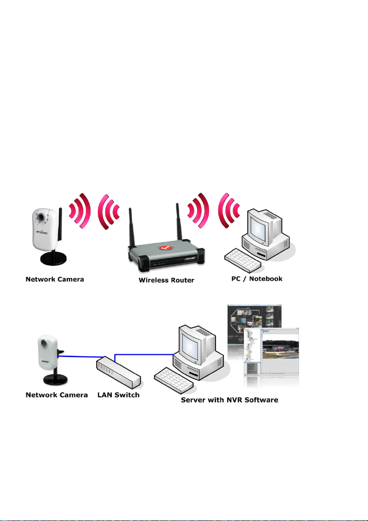
Example showing a wireless network camera in a typical setup
Example showing a network camera in a typical setup with an NVR recording
solution
- 6 -
Page 7

1.2 Model Overview
This user manual contains information for the following models:
Intellinet
Model
Number
551380 IDC-752IR Night Vision 720p Network Dome N75113
551397 IDC-757IR Outdoor Night Vision 720p Network Dome N77111
551410 IDC-767IR Outdoor Night Vision 1080p Network Dome N77210
551427 IDC-832 720p Network Mini-Dome N73100
551441 IDC-862 1080p Network Mini-Dome N73200
551434 IBC-607IR Outdoor Night Vision Network Bullet
551366 IBC-637IR Outdoor Night Vision 720p Network Bullet
551069 IBC-667IR Outdoor Night Vision 1080p Network Bullet
Product Model
Number in
16-channel
video
surveillance
software
N35010
Camera
N35111
Camera
N37210
Camera
- 7 -
Page 8

2: System Requirements
2.1 Hardware Requirements
Your computer hardware should meet or exceed the following
specifications:
Access to a single camera with Web browser:
CPU: Pentium 4 1600 MHz (or equivalent AMD)
Video Card: 64 MB graphic card
RAM: 512 MB
Network Adapter: 10/100 Mbps Fast Ethernet
Using the 16-Channel viewing / recording utility:
CPU: INTEL Dual Core Processor
Video Card: 64 MB graphic card
RAM: 2 GB
OS: Windows XP, Windows Vista or Windows 7/8
2.2 Operating System and Web Browser
Support
Intellinet network cameras support Web-browser based access for all major
operating systems.
Windows XP, Windows Vista and Windows 7/8
- MS Internet Explorer 8.x and 9.x (ActiveX)
- Firefox 15 or higher (Java)
- Google Chrome (Java)
- Opera 9.x (Java)
MacOS X Leopard
- Firefox 3.x (Java)
- Safari 3.x (Java)
Linux
- Firefox 3.x (Java)
- Konqueror (Java)
- 8 -
Page 9

2.3 Limitations
Web Browser Access
While it is possible to connect to the network camera with a Web browser other
than MS Internet Explorer, some of the features cannot be used. Refer to the
overview below:
MS Internet Explorer 8.x and 9.x (ActiveX)
- view live video in all formats
- record live video by right-clicking the live video
- listen to audio
- use a microphone to send audio to the camera
- view the video in full-screen mode
- use the digital zoom function
- access the administrator menu and configure the camera
- setting up privacy masking, motion and audio detection
All other browsers (Java)
- view live video in Motion-JPE G format
- access the administrator menu and configure the camera
(with certain limitations)
IP Installer
This application is only compatible to Windows operating systems.
Installation on MacOS systems can be done using the Bonjour discovery service
while the installation on Linux systems requi r es manually changing the IP
address of the system to gain access to the camera. Refer to section 4.1
Connecting to the Camera for installa tion instructions.
16-Channel Viewing / Recording Utility
This application is only compatible to Windows operating systems. Visit
www.networkipcamera.com for a complete list of compatible applications.
- 9 -
Page 10

3: Package Contents
You should find the following items in the packaging of your Intellinet video
surveillance product.
1. Network dome camera
2. Quick installation guide
3. Installation CD
4. Mounting hardware and tool
7. Power adapter
-> Input: 110/230 V, 50/60 Hz
If any items are missing, contact your dealer.
-> User manual
-> Hardware installation guide
-> IP Installer Utility
-> Multi-Channel IP Surveillance Utility
-> Output: -12 V DC (other models)
- 10 -
Page 11

4: Installation
4.1 Connecting to the Camera
Connect the RJ45 network cable from th e camera’s LAN port to your network;
e.g., the router or a LAN switch, then power on the camera . The boot sequence
will take about one minute. You will need to use the camera’s power adapter, or
you can connect the RJ45 cable to a PoE-enabled switch or injector to power
the camera.
By default, the network camera (or video server) searches for a DHCP server
on the network and obtains an IP address automatically. A very common DHCP
server is a router, a device that is found on most networks.
The presence of a DHCP server on your network simplifies the installation and
users with limited knowledge of TCP/IP networks can install the network
camera in minutes. If no DHCP server is found, the network camera will revert
to its default IP address 192.168.1.221.
On Windows systems, you want to use the IP Installer utility t hat finds the
camera on the network and lets you make changes to the configuration.
Once the camera is set up properly, it can be accessed with the computer’s
Web browser. The following sections describe the procedure for Windows,
MacOS and Linux users.
- 11 -
Page 12
4.1.1 Windows XP, Vista and Windows 7
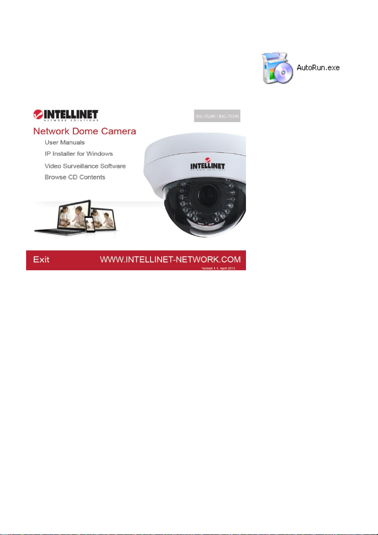
Insert the Installation CD into the CD or DVD-Drive.
After a few moments, the CD will automatically start
and display the screen below. If that does not happen,
you need to browse the CD with Windows Explorer and
double-click the autorun.exe file.
1. User Manuals
The user manual for the Intellinet Net w ork Camera is available in electronic
form on the installation CD, along with user manuals in different
languages.
If you encounter differences between the screen shots show n in the user
manual and the actual screen contents, it is recommended that you open
the manual from the CD, as it may be a newer editio n than the printed
version.
2. IP Installer for Windows
This utility is designed to find the network camera on your network and lets
you make changes to the configuration.
3. Video Surveillance Software
Refer to Chapter 6 Video Surveillance Software.
- 12 -
Page 13
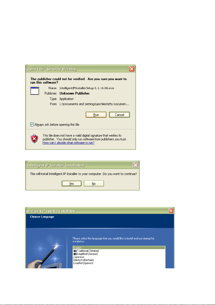
IP Installer for Windows Installation
Before you start with the installation, make sure that you are connected to
your computer with a user account that has administrator rights. The
screen shots below are taken from an installation on a Wind ows XP system.
The procedure on Vista and Windows 7/8 systems is similar.
To begin the installation, click on the link “IP Installer for Windows.” After
that, depending on your system’s settings, you may see t he message
shown below.
Click on “Run” to continue …
… and click on “Yes” to begin the installation.
Select your preferred installation language, and then click o n “Next.”
Click on “Next” on the following screen as well.
- 13 -
Page 14

Specify the location where the program should be installed. The default path is
OK to be used on most systems. Click on “Browse…” to select a different
location and click on “Next” to continue.
Select the Windows Start Menu folder.
Select or de-select the optional Xvid Codec and MSN Plugin. If you are not sure
about these options, it is recommended to keep them selected.
Click “Next” to continue.
- 14 -
Page 15

Verify the installation summary and click “Install” to begin the installation.
Once the installation has completed, click on “Finish”.
A new shortcut has been created on your computer
desktop; Double-click it to start th e application.
- 15 -
Page 16
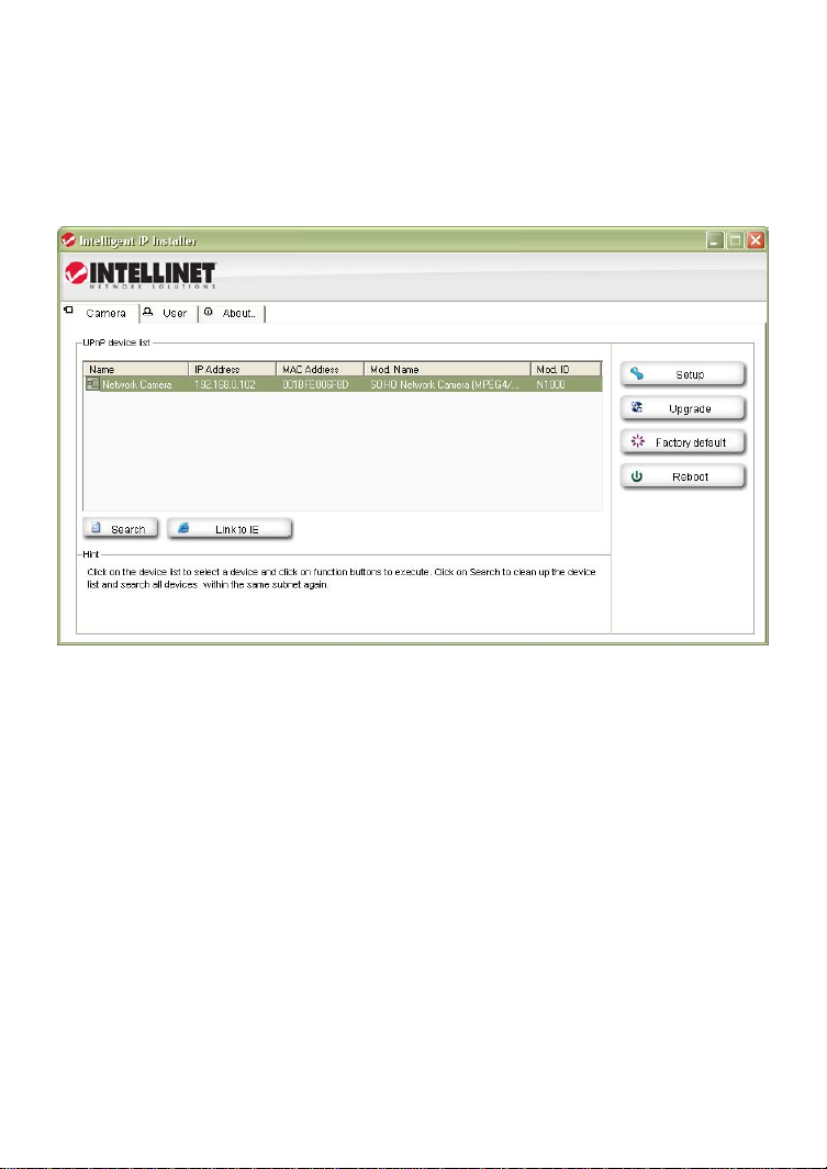
IP Installer for Windows
When the program starts, you are presented with the screen shown below.
Depending on your camera model, the screen may look slightly different, but
the functionality is the same. The IP Installe r utility lists all cameras that can be
found on your network. With this utility you can make changes to the
configuration, perform a firmware upgrade, restore the camera to factory
default values, and reboot the camera. Note: It may take up to three minutes
for IP Installer to show a camera that has been recently (re-)started.
The application has three main tabs: Camera, User and About.
Camera tab
UPnP device list: All cameras that are found on the network are displayed on
this tab. Cameras that are shown in red are currently
configured for a different network and cannot be accessed
with the Web browser before the IP settings of the camera
have been adjusted to your network (see Setup).
Search: The Search button can be used to refresh the view. Typically
it is not required to push the button, as the utility starts
scanning the network as soon as it is started.
Link to IE: Select the camera from the list and click this button to open
the camera with MS Internet Explorer. Note: This function
does not work for other Web browsers; however, you can
open the browser manually and open the URL
http://camera_ip_as_shown_in_list (in the example above,
you would open http://192.168.0.102).
- 16 -
Page 17
Setup: Select a camera from the list and click the Setup button in
Upgrade: Select a camera from the list and click the Upgrade button if
Factory default: If you want to reset the camera settings to factory default
order to open the camera configuration dialog.
you wish to upgrade the firmware of the camera. The
firmware upgrade can also be performed with your Web
browser.
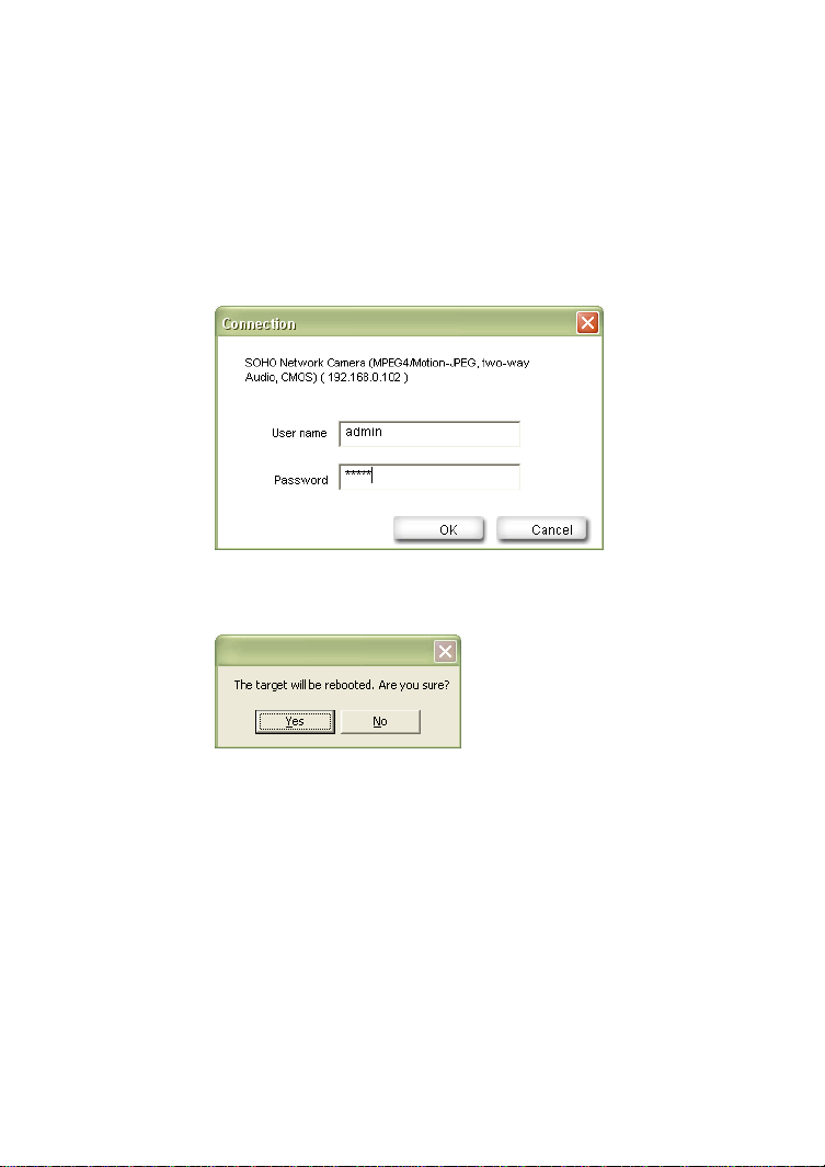
values, you can select a camera from the device list and click
this button. When you do this, you will be asked to enter the
administrator user name and password:
Enter “admin” for both.
You will then see the following message:
Click Yes to perform the factory reset.
Reboot: This function lets you reboot the camera. The procedure is
identical to the factory default function, except the camera
does not lose the settings.
Camera Tab – Setup Function
When you click on the Setup button, you first need to enter a valid
administrator user name and password (see above). You will then be pres ented
with the first page of the Setup menu. The first page shows so me basic
information about the camera.
Click the Next button to open the next page.
- 17 -
Page 18
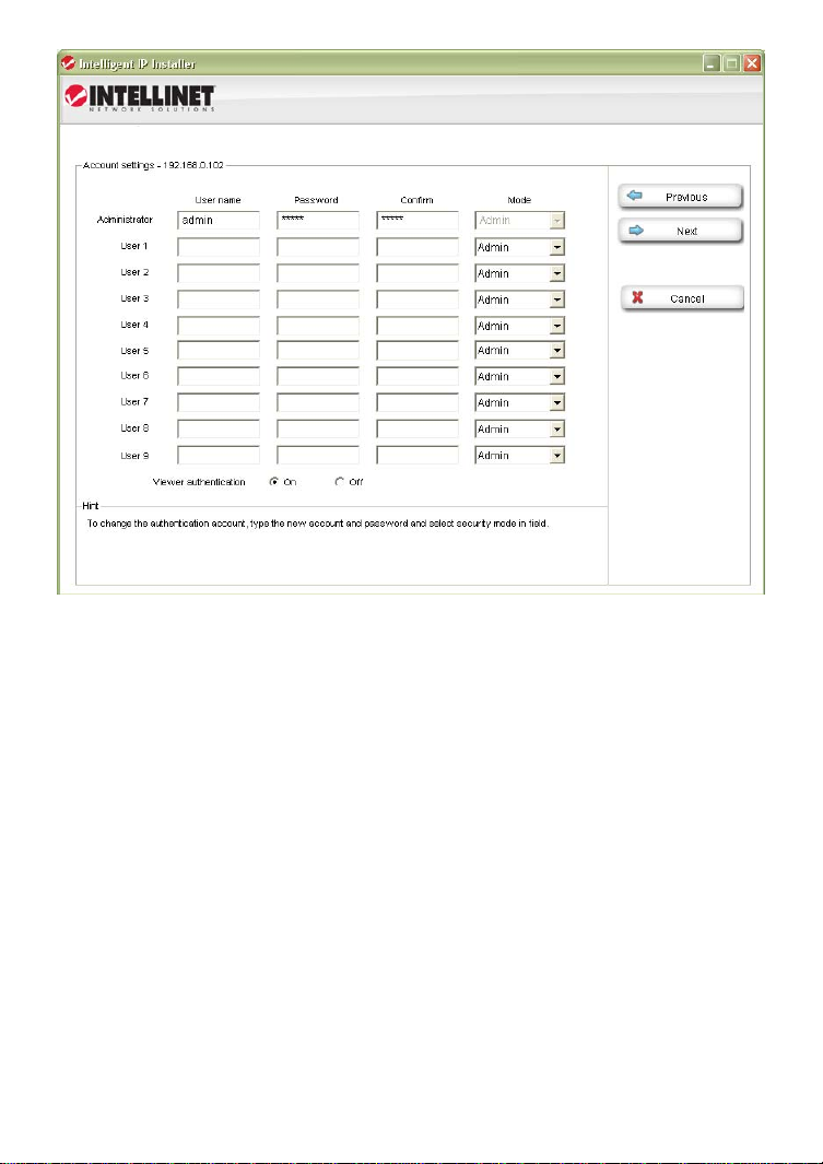
User Account Settings Page
User Name: Enter the user name you wish to use for the new account.
Password: Enter the password for the new user account.
Confirm: Type the password in again.
Mode: There are three possible values to choose from:
1. Admin: User has full access to all camera functions.
2. Operator: User can view the live image and change image
related settings such as brightness, contrast , etc.
3. Viewer: User can view the live video of th e camera, but is
unable to make any changes to the configuration.
Viewer
Authentication: On: Every user that connects to the camera has to enter a
valid user name and password.
Off: A user name and password is only required if the user
wants to change camera-related settings. By setting the
Viewer authentication to off, you allow any user to view the
camera’s live image.
Click the Next button to open the next configuration page.
- 18 -
Page 19
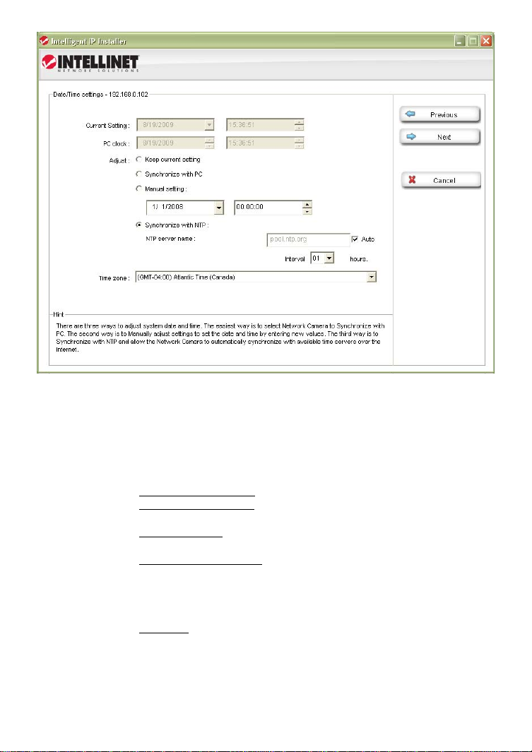
Date/Time Settings Page
The network camera is equipped with an internal clock. You can display the
current date and time information on the video, so that when you look at
recorded video material or images you can easily tell when the recording was
made. Before you can use this function, you need to defin e how the camera
obtains the time.
Current Setting: Displays the current date and time.
PC clock: Displays the time of the PC that you are using right now.
Adjust: Keep curre nt setting – no changes are made.
Synchronize with PC – instructs the camera to retrieve the
current date and time from the PC.
Manual setting - allows you to set up the date and time
yourself.
Synchronize with NTP – The camera will obtain the time from
an NTP server. Normally it is no t required to change the NTP
server, as the default server “pool.ntp.org” is always
available. You can, however, manually overwrite the NTP
server by un-checking the option “auto.”
Interval: Define how often the camera should re-synchronize
the time with the NTP server’s time.
Time Zone: Select the correct time zone for the camera to display the
correct date and time.
Click the Next button to open the next configuration page.
- 19 -
Page 20
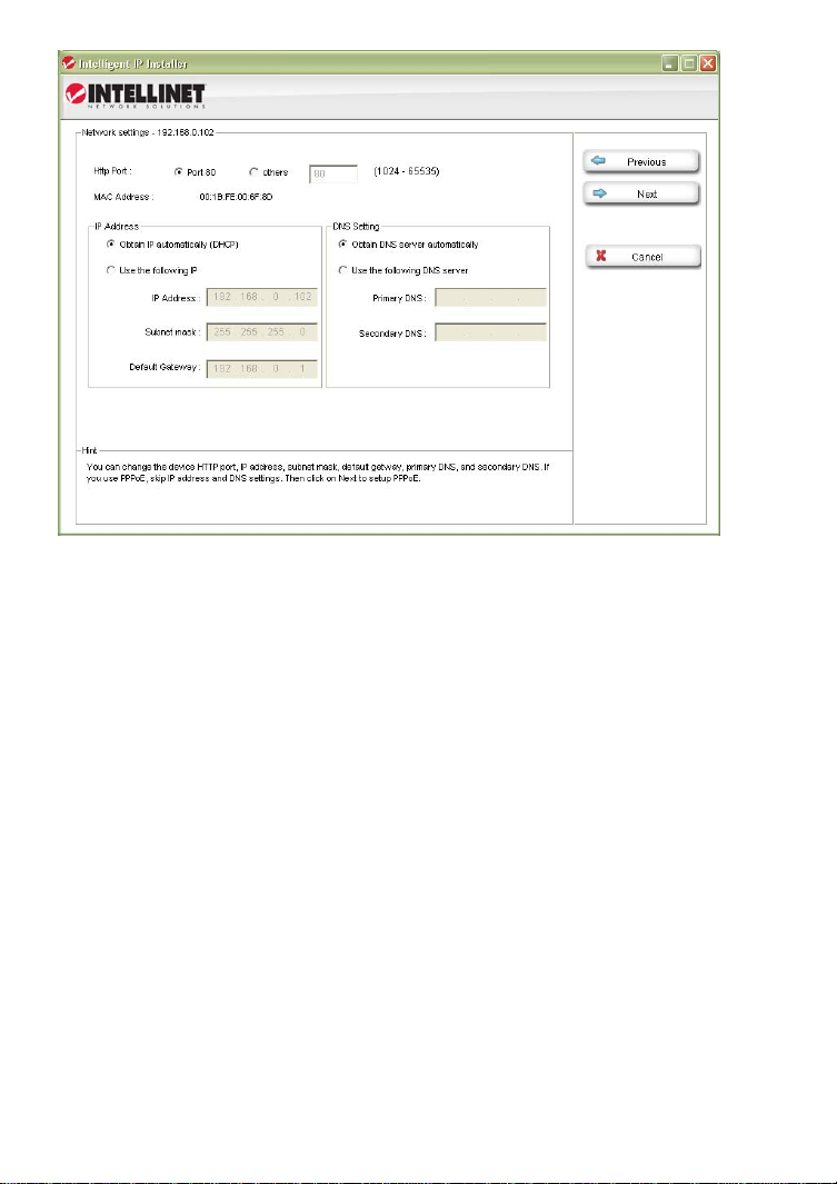
Network Settings Page
The default configuration is shown above, and for most users there should be
no need to change these settings. Advanced users can change the following
values:
HTTP Port: This is the Web server port of the camera. The default value
is 80. You can change the value from 80 to a value between
1024 and 65535. Note that when you change the HTTP port,
you need to append the new port to the address of the
camera; e.g., http://192.168.0.102:1024.
IP Address: By default the camera obtains the IP address from a DHCP
server in the network. You can set up the camera with a static
IP address as well by activating the option “Use the follow ing
IP.” If you are not familiar with IP addresses in general or the
IP address setup of your network, you should contact your
network administrator for the correct values.
DNS Setting: A DNS Server (DNS stands for Domain Name System) allows
the camera to contact an e-mail, FTP or NTP server using its
proper domain name (e.g., mail.mydomain.com) rather than
its IP address. If you set up the camera with a static IP
address, chances are that you will need to provide the DNS
server settings yourself as well.
Click the Next button to open the next configuration page.
- 20 -
Page 21
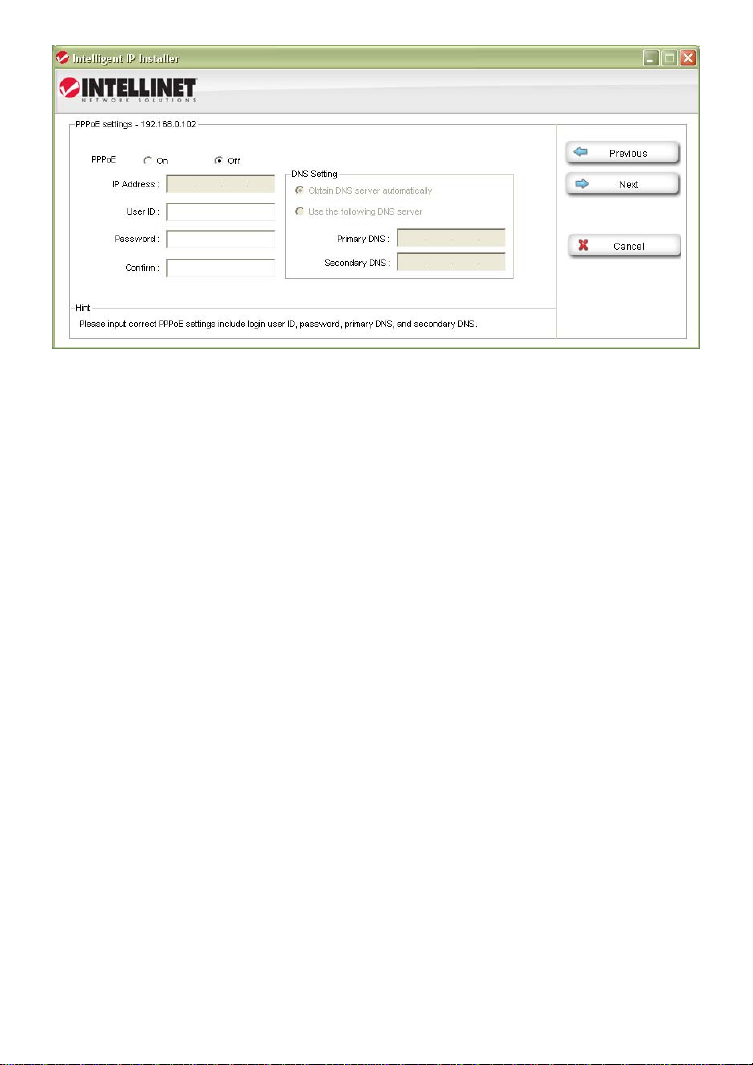
PPPoE Settings Page
This page allows defining of the PPPoE settings of the camera. This function is
not required for the vast majority of users, and if you are not planning on
connecting the camera directly to a DSL modem (no network present, just the
camera connects directly to the modem) you can safely skip this pa ge.
PPPoE is a common connection method for ADSL Internet services. It is not
required for cable modem service, or newer DSL services that operate with
dynamic IP addresses.
PPPoE connections require a user ID and password that are typically provided
by your ISP (Internet Service Provider). If there is no router in your network,
and you connect the camera straight to the DSL modem, you need to enter the
user ID and password here, so that the camera can connect to the Internet.
Note: The camera does not support idle timeout, meaning, it stays connected
to the Internet indefinitely. Users of time- or volume-based Internet services
need to be aware of this as the camera can cause significant usage charges for
the service. It is always a better option to have the router handle the PPPoE
connection to the Internet Service Provider, instead of the camera.
Click the Next button to open the next configuration page.
- 21 -
Page 22
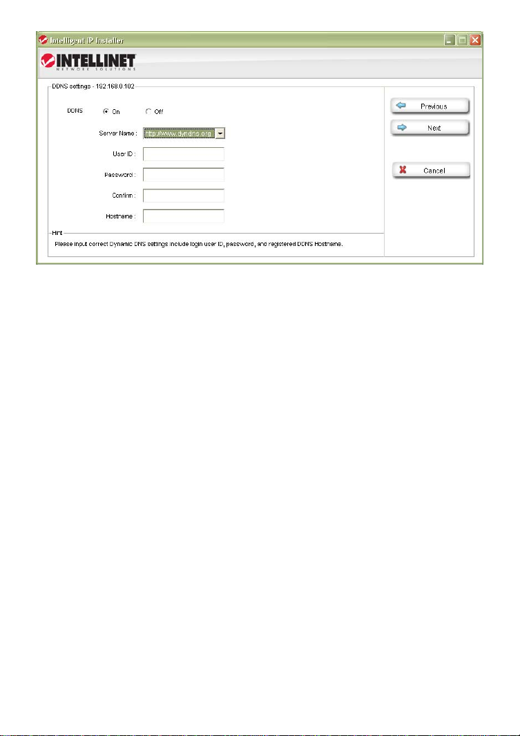
DDNS Settings Page
DDNS stands for “Dynamic DNS.” DDNS is useful for all users who have an
Internet service with a dynamic IP address. Most DSL services u tilize IP
addresses that are highly dynamic and change as often as once every 24 hours.
Cable modem services typically keep the IP address assigned to a user for a
longer period of time; e.g., up to 30 days. In any case, after a certain amount
of time the IP address of your network will change unless you have a more
business-type Internet service that provides a permanent, static IP address.
Why does it matter if the IP address that the ISP assigns to you changes? If
you never want to access the camera remotely over the Internet, it wouldn’t
and you can skip this section.
If you want to connect to your camera from outside y o ur network, the changing
IP addresses will make this task very complicated, as you never know under
which IP address you can reach your camera. DDNS is the solution to the
problem. Services like DYNDNS.ORG allow signing up for a free account and
setting up domain names like “mycamera.dyndns.org.” T he DDNS service
assigns the current IP address that your ISP has assigned to you to the domain
name you have set up, so that you can always reach your camera at
http://mycamera.dyndns.org (example).
Note: We recommend using the DDNS client that is integrated in your router for
the DDNS service instead of the camera’s DDNS cli ent.
The network camera supports three DDNS providers:
DYNDNS.ORG, DHS.ORG and TZO.ORG.
Server name: Select the service (e.g., DYNDNS.O RG)
User ID: Enter your DDNS user account password here.
Password: Enter the password of your DDNS account here.
Confirm: Repeat the DDNS account password here.
Hostname: Enter the dynamic host name (e.g., “mycamera.dynsns.org”
here. Do not enter http://
Click the Next button to open the next configuration page.
- 22 -
Page 23
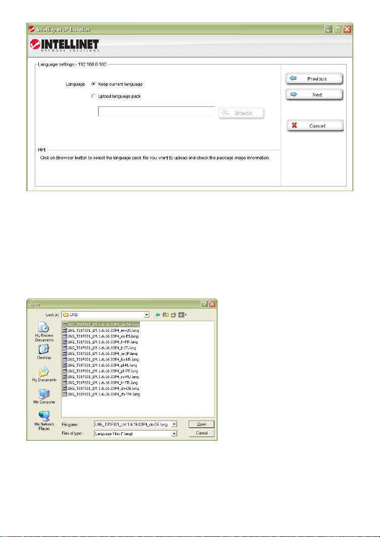
Language Settings Page
The Intellinet network camera pr ovides a multi-language user interface for
Web-browser access. In order to use this function, you first need to install the
additional languages by uploading them to the camera. The default language is
English. Additional languages can be found on the Installation CD, or you can
download them from the Intellinet Web site at www.networkipcamera.com.
In order to install an additional language, activ ate the option “Upload language
pack” and click Browse. Then select the folder where the language files are
located. The image below shows the available file s.
Select the file of choice and click Open to get back to the language settings
page. Note the file location has been entered in the field in front of the Browse
button.
Click the Next button to open the final configuration page.
- 23 -
Page 24
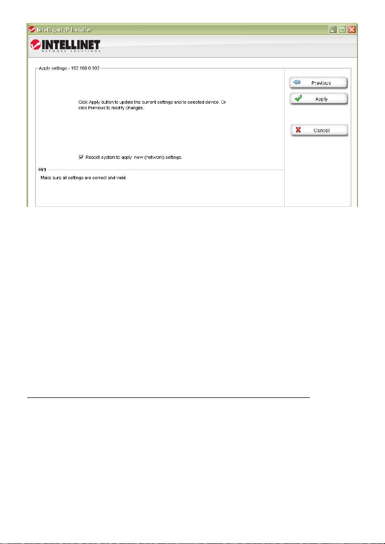
Apply Settings Page
This is the last page of the Setup.
All configuration changes you have mad e on the previous screens will be saved
when you click the Apply button. If you have selected an additional language to
be installed on the previous page, cl icking Apply will install that language as
well.
After you click Apply, the main screen of IP Installer shows up, and after a
period of 60 to 180 seconds, the camera will show up in the UPnP device list.
You may need to click the Search button to get the camera to show up again.
Camera tab – Upgrade function
The firmware is basically the operating system of the camera. New functions
are introduced from time to time, and compatibility patches and fixes are
released to make your Intellinet camera an even better product. A firmware
upgrade replaces the internal camera software with a new version.
Note: A failed firmware upgrade can render your camera inoperable.
Before you start with the firmware upgrade, ask yourself a few questions:
1. Has Technical Support instructed me to upgrade, or is my camera operating
erratically or do certain functions in the camera not work as they should?
2. Am I absolutely sure that I downloaded the correct firmware file for my
camera from the Intellinet Web site?
3. Can I be reasonably certain that the power will not go out during the next 10
minutes?
4. Are all unnecessary programs on my computer closed?
- 24 -
Page 25

5. Will the battery in my notebook last for at least another 10 minutes?
6. Is the camera I want to upgrade located in my local network?
7. Am I sure about what I am doing?
If you answer any of these questions with “no,” you should not perform the
firmware upgrade and skip this section.
Select a network camera from the UPnP device list and click on Upgrade to
upgrade the firmware. As before, you have to key in the user name and
password of the administrator to enter the upgrade page. You will then see the
following screen:
Click on Browse and select the correct firmware file. The file must have the file
extension “.bin.” Click on Open to return to the firmware upgrade page. The
Upgrade button that was previously grayed out is now available.
Click the Upgrade button to begin the upgrade process. The upgrade takes
place in several stages. The screen informs you about t he progress. At the end
of the upgrade the status indicates “Rebooting” wh ile the progress bar moves
from 0 to 100%.
Note: Do not leave this screen and do not close the program yet. Wait for the
status to display “Done” and when it does, click on “Previous” to go back to the
main screen. As before, it may take up to three minutes for the camera to reappear.
- 25 -
Page 26

User tab
This screen offers two functions:
1. You can change the individual settings of the camera in a similar fashion as
with the Setup function on the main screen. However, instead of clicking on
Previous and Next to switch between the screens, you can access th e indi vidua l
options more quickly by clicking on any of the tabs (User, Date/Time, TCP/IP,
PPPoE and DDNS). You cannot install additional languages with this function,
however.
2. You can load the camera configuration into the IP Insta ller utility, and then
save it to your computer hard drive. This can be useful if you wish to create a
backup of the entire configuration in case you want to reload it at a later time.
You can also use this function to load a configuration previously saved on the
PC and load it back into the camera configuration.
To begin, select either “From PC File” or “From Device,” then click Load.
If you select “From PC File” you will be ask ed to specify the configuration file on
your computer hard drive.
If you select “From Device” a screen opens up that asks you to select the
camera and enter the administrator user name and password.
Once completed, the screen shows the configuration data, and you can make
changes to the settings as you see fit. When you are ready to submit the
settings to the camera, click on Apply. Select the camera from the device list,
enter the administrator user name and password and click OK. The camera
settings are now saved into the camera configuration.
If you want to create another backup of the configuration, click on Save and
enter a proper filename, such as “camera_1_config.conf,” before you click
Save.
- 26 -
Page 27
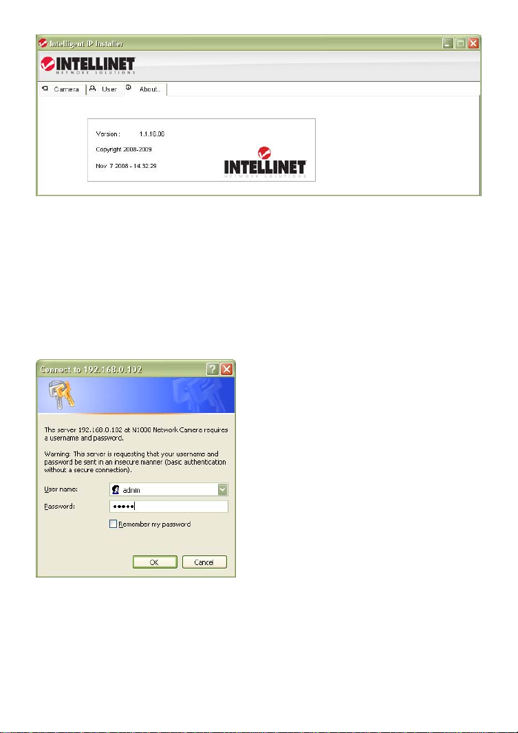
About tab
This screen displays the version number and date of the IP Installer utility. If
you need to contact the Intellinet Technical Support, make sure that you obtain
the information from this page and include it in your message to Technical
Support.
Accessing the camera
Select the camera from the UPnP device list and then click on Link to IE. MS
Internet Explorer will open the camera page automatically. You will be asked to
enter a valid user name and password for the camera unless you have disabled
the viewer authentication in the account settings.
Note: If clicking on the “Link to IE” button does not open up the MS Internet
Explorer Web browser, chances are that you are not a computer administrator.
In that case, login to your system again using a computer administrator
account.
Administrator rights are also required for the installation of the ActiveX control,
which is shown on the next page.
- 27 -
Page 28

When you connect to the Intelline t network camera for the first time with MS
Internet Explorer, you need to install an ActiveX control. The following message
appears:
Click on Install to being the installation. Depending on your system, additional
messages may appear; e.g., the Web browser notification bar. In any event,
you need to allow the installation of the ActiveX control.
Note: If this message does not show up and you only see the camera Web page
but no live image, the security settings in you Web browser’s Internet Options
are set too high. You need to change them to allow the execution of signed
ActiveX controls.
If the installation of the ActiveX co ntrol was successful, you should be looking
at the camera’s live video page a few moments later.
Refer to Chapter 5 for explanations on the Web interface options of your
INTELINET NETWORK SOLUTIONS Network Camera.
- 28 -
Page 29

4.1.2 MacOS
The installation on Apple systems running MacOS X does not involve the
Intellinet installation CD. The Intelline t network camera supports Apple’s
Bonjour service.
Bonjour, formerly Rendezvous, is Apple Inc.'s
trade name for its implementation of Zeroconf, a
service discovery protocol. Bonjour locates
devices such as printers or network cameras, as
well as other computers, and the services that
those devices offer on a local network using
multicast Domain Name System service records.
The software is built into Apple's Mac OS X
operating system from version 10.2 onward.
1. Open the Safari Web browser and open the Bookmarks toolbar, where you
will find the Bonjour link.
Screen shot shown of Safari 4.x.
- 29 -
Page 30

2. The Network Camera is shown in the category Webpages. In order to
connect to the camera, double-click the circled link. Safar i then connects to the
camera and the message below appears:
3. Type in “admin” for the user name and the password, then click on Log In.
Refer to Chapter 5 for explanations on the Web interface options of your
network camera.
- 30 -
Page 31

4.1.3 Linux
The installation on Linux systems does not require any
special software. The network cam era is compatible to
Web browsers such as Firefox and Konqueror.
The initial installation requires the setup of the
camera’s IP address. As the camera by default obtains
an IP address from a DHCP server in the network (e.g.,
a router), you can access the camera as soon as you
have obtained the IP address from the router’s DHCP
client log. Alternatively, you may use Bonjour
(mDNSResponder), which is also available for Linux.
If no DHCP server is connected to your network, the camera reverts to its
default IP address 192.168.1.221. In order to gain access to the camera, you
need to change the IP settings of your system manually. Set up the IP address
to be in range of 192.168.1.xxx (where xxx is not 221). Then open your Web
browser and connect to address http://192.168.1.221. Log in to the camera
and click on the Settings link to open the administrator menu. Refer to section
5.2 Settings Page for more details.
- 31 -
Page 32

5: Web Browser Interface
5.1 Live Video Page
Use this button to take a
snapshot of the video. Clicking
the button opens up a window
showing the captured frame.
Save the image by clicking on
the Save Image button.
Note: This function is only
available in MS Internet Explorer
on Windows systems.
- 32 -
Page 33

Click on the Record button, if
you wish to record the live
video to your computer’s hard
drive. When selected, a prompt
will request you to specify the
folder in which you want to
store the video.
Click OK to begin the recording.
The Record button starts
flashing, indicating that the
recording is active. Click it
again to stop the recording.
In case the recording does not
start, you need to run MS Internet
Explorer as Computer
Administrator.
Note: This function is only av aila ble in MS Internet Explorer on
Windows systems. The recorded video format is Motion JPEG (MJPEG). It should be noted that Windows Media Player is not able to
playback that video format. The free VLC media player
(videolan.org) or QuickTime play er (apple.com/quicktime) are able
to play the camera video without any problems.
Click these buttons to pause or resume from pause the live video
stream.
Note: This function is only av aila ble in MS Internet Explorer on
Windows systems.
Clicking this button will stop the video stream and the video display
turns black (off).
Note: This function is only av aila ble in MS Internet Explorer on
Windows systems.
- 33 -
Page 34
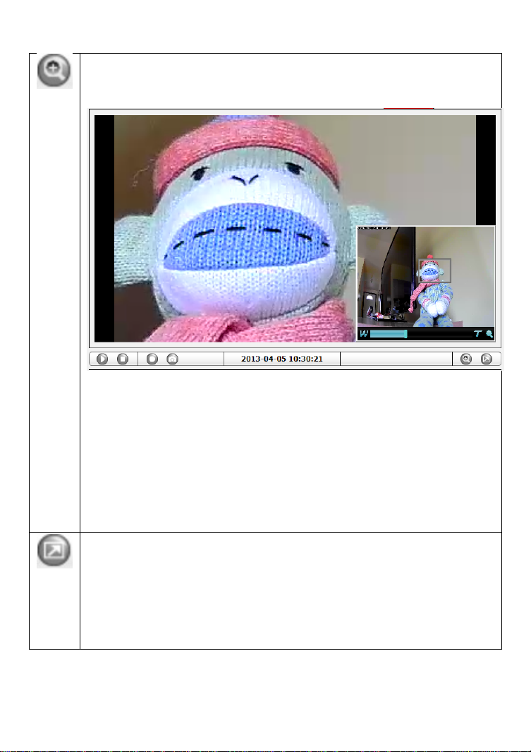
The digital zoom function allows magnif ication of certain areas of the
video. After you click on the magnification icon, a window appears as
an overlay on top of the image. See below.
You can drag the box over the image, and you can adjust the
magnification by moving the slider toward “T” (tele-zoom) or “W”
(wide-angle). The more you move the slider toward “T,” the further
you zoom in and details appear larger. It is normal behavior that the
image quality is reduced when using the digital zoom function.
Digital Zoom is only available in MS Internet Explorer Web browsers.
Note: This function is only av aila ble in MS Internet Explorer on
Windows systems.
Click this button to view the video in full screen mode. In full screen
mode, the video is stretched to fit the entire screen and all control
graphics and window elements are no longer displayed. To return from
full screen mode, press the ESC key on your keyboard. You can also
right- or left-click any part of the image with your mouse.
Note: This function is only av aila ble in MS Internet Explorer on
Windows systems.
- 34 -
Page 35
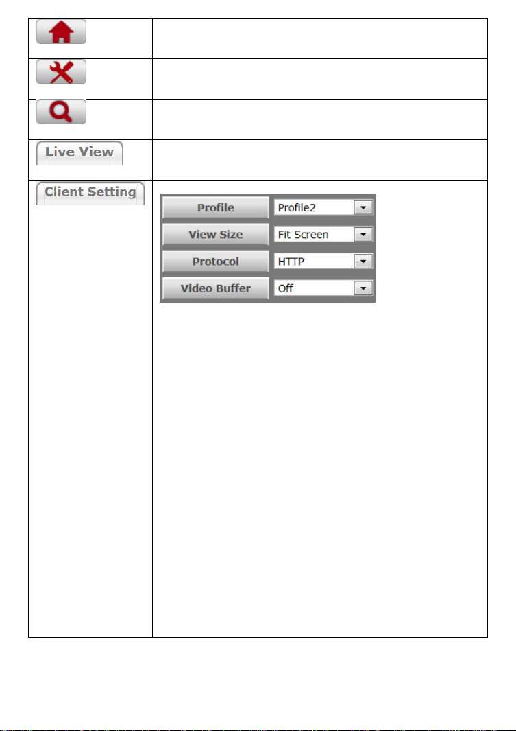
This button takes you back to the camera home page
where you can view the live video.
Click on this button to open the administrator menu
page, which allows configuring the camera.
This button opens up the integrated online help providing
useful tips on the various features.
Returns the user to the main live video page.
Click this button and the client settings dialog will open.
Profile: Select your preferred profile from the drop-down
list. Your Intellinet network camera can store different
profiles that provide different video settings. You can
define these profiles in the administrator menu, e.g, one
profile is for low bandwidth environment whereas another
pfofile is for maximum quality.
View Size: There are two choices here. “Fit Screen” will
keep the video small so that it will always fit into the
view port of the live video page. “Full Screen” is actually
not full screen at all, but it displays the v ideo stream at
it’s normal size. So, if you select a profile that displays
1080p contents and select full screen for the view size,
the video will be rendered at 1920 x 1080 pixels on your
screen.
Protocol: Select the transfer protocol here.
Video Buffer: If you turn video buffering on, the video
will display more smoothly at the expense of added delay
between the actions in front of the camera lens and when
you see them on the screen. If you want to minimize that
delay, you need to set the video buffer to “Off.”
- 35 -
Page 36

5.2 Settings Page (Administrator Menu)
The camera’s administrator menu allows you to configure all aspects of your
Intellinet network camera.
This page provides a complete overview of the status of your network camera.
The page may be a little bit intimidating at first glance as a lot of information is
displayed, but once you get more familiar with your camera, these values will
start to make sense to you.
5.2.1 Basic Setup
The basic setup allows you to manage the user
accounts of your network camera, define the network
parameters, set up the date and time settings and
most importantly, the video settings. This is a video
surveillance camera after all.
Account
The Intellinet network camera allows the creation of different user accounts
with different levels of access to the camera. There are three main user levels.
The Viewer account only allows viewing the live video pag e of the camera. The
Operator account allows viewing the live video as well as changing the image
setup settings, such as brightness, contrast, etc. Only the Administrator
account has full access to all camera settings, including the Settings menu.
You can define up to nine additional user accounts. The user name and
password must be between 4 and 16 characters in length. For each account you
can also specify the viewer mode (Administrator, Operator or Viewer).
Click the Add button to create a new
user account. A popup window will
open up. Here you type in a user name
and a password for the new account.
Also, you must define the role of the
new user account. The example shows
how we create a guest account that
only has viewing rights, but cannot
change any settings.
Click Save to create the new user account.
- 36 -
Page 37

Highlight an account to either edit or remove it.
Note that the admin user account cannot be removed.
Anonymous Settings
Enabling this will allow any user to view the live video from the camera live
video page without entering a user name or password. If you do not want to
allow this to happen, be sure to set this option to “Disabled.”
- 37 -
Page 38

Network - TCP/IP
On this page you can define the network settings of the camera. By default the
camera is set up to automatically obtain the ne cessary IP information from the
DHCP server (e.g., the router) in your network. You can, however, set up the IP
address and related settings manually.
MAC address:
MAC address stands for Media Access Control address. This is the unique
hardware address of the camera’s network interface.
Obtain an IP address automatically (DHCP):
This is the default setting. In this mode the camera obtains the IP information
from the DHCP server in your network.
Use the following IP address:
Activate this option in order to assign a static IP address to the camera. You
need to enter a valid IP address, subnet mask and default gateway address in
the corresponding fields.
Use the following DNS server address:
When you disable DHCP, you also need to provide the camera with valid DNS
settings. The Primary DNS server must be filled out. It is often the same IP
address as the Gateway address.
HTTP port number:
The default value is 80 and normally there is no need to change it. If you
decide to change the http port to a different value; e.g., 1024, you need to do
two things:
1. After saving the settings you need to reboot the camera via the System ->
Initialize menu.
2. After the reboot is completed you need to connect to the camera using the
URL http://camera_ip:portnumber.
PPPoE is the most common form of connection for DSL-based Internet service.
- 38 -
Page 39
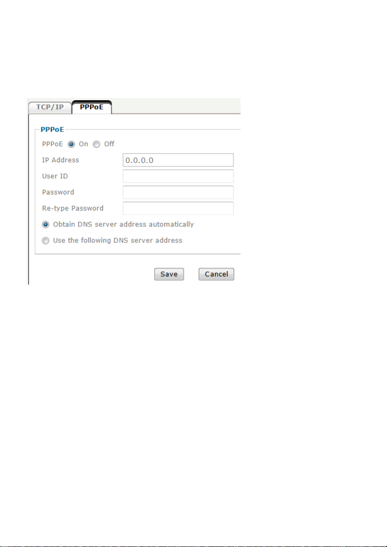
Network - PPPoE
You can use this function to connect the camera directly to a DSL modem. A
common application for this is where the network camera is installed in a
remote location where no network is present. In the location is a DSL Internet
connection (DSL modem), but no router or any other network infrastructure.
You can connect the camera to the DSL modem and enter your DSL account
information in the fields below.
IP address: Displays the current IP address obtained from the Internet
Service Provider (ISP). It displays 0.0.0.0 if the camera is not
connected to the Internet via PPPoE.
User ID: Enter the user ID for your DSL service here. The user ID has
been given to you by your ISP.
Password: The password for the DSL account goes here. Re-type the
password in the field below.
DNS Server:
Typically, your ISP will send DNS Server information to the camera when it
connects. Some ISPs, however, require entering specific DNS servers manually.
In that case you can activate the option “Use the following DNS server address”
and enter the primary and secondary DNS servers in the fields below (not
shown on the screen shot).
- 39 -
Page 40
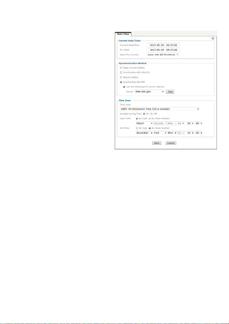
Date Time
On this page you can define the time settings of the camera.
Current date/time:
Displays the camera’s current time.
PC clock:
This is the date and time of the
computer you are currently using to
connect to the camera.
Date/Time format:
The format determines how the
date/time is displayed on the live
video.
Syncronization Method:
“Keep current setting” means that
you don’t want to change the date
and time.
“Synchronize with client PC” adjusts
the camera time to the time of your
PC. Be aware of the fact that this option sets the time only one time. From that
point forward, the camera time will start to differ from your PC time as time
progresses, and occasional re-synchronization will be necessary.
“Manual Setting” lets you manually enter the time and date. As with the
previous option, the camera’s time will become inaccurate as time passes and
you will need to re-synchronize the time periodically.
“Synchronize with NTP”: This option is the recommended setting. In this mode,
the camera will synchronize its time settings based on the interval setting
(ranging from once per hour to once per day). The camera obtains the time
from the NTP server. You can use the default value unless your camera is not
connected to the Internet, or if a firewall in your network blocks the outgoing
NTP request of the camera. Select “Manual” and you can enter a different NTP
server; e.g., a server in your local network.
Time zone:
Select the correct time zone for your location.
Daylight Saving Time:
You can define the range of Daylight Saving Time by activatin g this option. The
camera will adjust the time (move the clock forward or backward by one hour)
depending on the programmed start and end time. If your camera is not
equipped with this feature, you can adjust the time zone manually for Daylight
Saving Time.
- 40 -
Page 41
Video – Video Settings
The following three menus (Video Settings, Profile and Day/Night) a llowing
defining all video-related parameters. No te that the Day/Night option as well as
other parameters may not be available on all models.
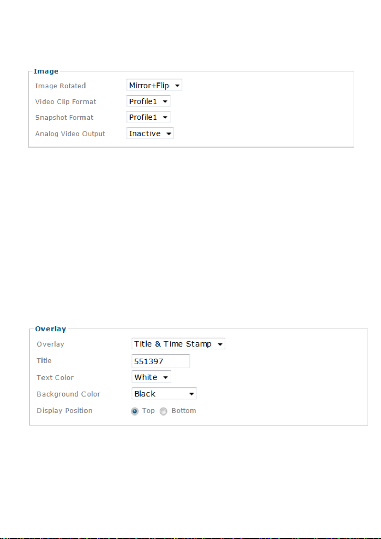
Image Rotated:
Allows mirroring and rotating the image.
Video Clip Format:
Select which video profile the camera should be using for video clips it records
in a network storage device.
Snapshot Format:
Select the video profile used for snapshots (e.g., for JPG upload to a FTP
server).
Analog Video Output:
If your camera is equipped with an analog video output, you can activate or
deactivate it here.
Overlay:
Define what kind of an overlay you want for the live video.
Title:
A short name for the camera that can be used as an overlay.
- 41 -
Page 42

Text Color:
Choose between black or white.
Background color:
Select from either black, white or transparent.
Display Position:
Define where the overlay should appear on the live image.
Privacy masking is the ability of the camera to back out (censor) certain parts
of the live video.
Example 1: The camera is installed in
your home: e.g., overlooking your
driveway. In the background is the
neighbor’s house, which you have no
intention of monitoring. It would illegal in
some cases for you to do so. To resolve
this problem, you can activate a privacy
zone over your neighbor’s house.
Example 2: The camera is installed in
your company; for example, overlooking
the warehouse. In one corner of the
warehouse is the break room, where the
employees go for their lunch breaks. In
many countries it is not permitted to
monitor the workers during their break.
To comply with laws and regulations, you
can define a privacy mask in the break
area to ensure that this area is not being
monitored or recorded by the camera.
Click “Add” to create a new privacy mask.
- 42 -
Page 43

As you can create multiple masks, you need to provide a name for the mask,
and you can define which color you want to overlay to be. Finally, set the status
to “Enabled” and click “Save” to create and activate the privacy mask.
->
Video – Profile
The Intellinet network camera allows the creation of video streaming profiles.
For each profile you can define the video resolution, the viewing area and the
video codec that is to be used.
Click “Add” to create a new profile, “remove” to delete a profile or “Edit” to
modify an existing profile.
- 43 -
Page 44

Encoding: Your Intellinet network camera can encode vid eo in three different
formats. H.264 is the most advanced and efficient codec delivering excellent
image quality and a small video stream size at the same time. Normally, this is
your preferred choice. However, you can also select MPEG4 or MJPEG, e.g., for
compatibility reasons.
View Area: The camera allows you to create different viewing areas. Tho se are
defined in the Menu Live View -> Camera Setting -> View Setting. You can
assign one of those viewing areas to the profile.
Resolution: Here you define the video resolution for the profile. Which choices
you have depend on your camera model. Some HD models offer image
resolutions of up to 1920 x 1080 pixels whereas standard definition cameras
are limited to 640 x 480 pixels.
- 44 -
Page 45

Maximum frame rate: Type in the number of frames the camera should
generate per second of video. The higher the value, the smoother the video,
but the more bandwidth is going to be req uired. Valid entries are 1 to 30.
Quality: You can control the image quality of the video by selecting “Fixed
Quality” and defining the image quality by selecting one of the following values
“Medium,” “Standard,” “Good,” “Detailed” and “Excellent.” Or you can choose to
specify the bit rate of the video the camera must not exceed. In this mode the
camera varies the image quality automat ically to not exceed the specified
maximum.
Video – Day/Night
Some Intellinet network cameras are equipped with active IR LEDs providing
the ability to capture video in complete darkness. Note, that if your camera is
not equipped with IR LEDs, this menu will not be available. Also note that some
menu items will vary depending on your camera model.
Infrared cut-off filters are designed to reflect or block mid-infrared wavelengths
while passing visible light. They are often used in network video cameras to
block IR due to the high sensitivity of many camera sensors to near-infrared
light. With the filter in place before the image sensor, the camera will not be
able to pick up IR light, but it generates true color video. Once the IR cut filter
is removed, the camera becomes IR light sensitive and will generate a black
and white image – and it does that even in complete darkness if the IR LEDs
are active.
IR Cut Filter Mode:
“Auto” – The camera decides when to remove the IR cut filter based on the IR
Cut Filter Threshold you can specify. The switch delay ensures that the camera
only switches the IR Cut Filter after the specified amount of time has passed.
“Day Mode” – In this mode the camera does not remove the IR Cut Filter from
the image sensor regardless of any other settings. Select the day mode if you
don’t want the Intellinet network camera to capture video in low light conditions
or darkness.
- 45 -
Page 46

“Night Mode” – This is the opposite of the day mode. If this mode is enabled,
the camera always removes the IR cut filter. As a result, the camera will always
be IR sensitive, regardless of the actual light levels. Using night mode in day
light conditions is not recommended as it leads to a poor image qua lity with
false and washed out colors.
“Schedule” – Select this option, if you wish to control exactly when you want
the camera to engage the night mode. You can use the internal scheduler to
define a time pattern for each day of the week, e.g., no night mode on the
weekends, but night mode from MON to FRI from 21.00 hours to 06.00 hours.
The scheduler is explained in detail later on.
IR Mode:
“Auto” – This ensures that the IR lights go on whe never the IR cut filter has
been removed.
“Active” – keeps the IR LEDs illuminated regardless of the state of the IR cut
filter. To ensure maximum life of the IR LEDs, this option shouldn’t be used,
unless your camera is installed in a dark environment which requires IR lighting
at all times.
“Inactive” – When this is selected, the camera will never active its IR LEDs,
even if the night mode is enabled (the IR Cut Filter has been removed). If you
have your own 850nm IR lighting in place already, then you will not need to
use the camera’s integrated IR LEDs and can therefore turn the IR LEDs off.
IR Level (Spot/Wide):
Use this to control the lighting pattern of the IR LEDs. Some models allow you
to control the center of the image (“spot”) independently from the outer areas.
If you want a more evenly lit image, reduce the spot level close to 0 and set
the wide level to 100. If you want to focus on the center of the image instead of
its surroundings, you raise the spot value and lower the wide value.
- 46 -
Page 47

5.2.2 Live View
The live view menu provides access to the video
settings, which are exactly the same as described in the
last section (5.2.1). It also provides access to advanced
image settings and allows configuring the view ar eas
that we discussed in the previous section. Note that depending on your camera
model, the options on the screen may differ from the screen shots in this user
manual.
Camera Settings – Image Settings
The image enhancement controls consist of standard video settings, which you
know from a great variety of products. Click on “Video” to see the camera live
video while you adjust the settings to your liking.
Color Tone: Choose between “Real,” “Cool” or “Warm”. Normally you want to
set this to “Real” as it provides the best representation of natural colors.
Auto White Balance: This parameter controls how the camera interprets colors.
You can choose from the following values: “Auto,” “Fluorescent,”
“Incandescent,” “Sunny,” “Cloudy” or “Sun Shade.” You should select t he value
that best represents the environment th e camera is installed in. You can also
leave the default value “Auto,” as it typically delivers very good results.
- 47 -
Page 48
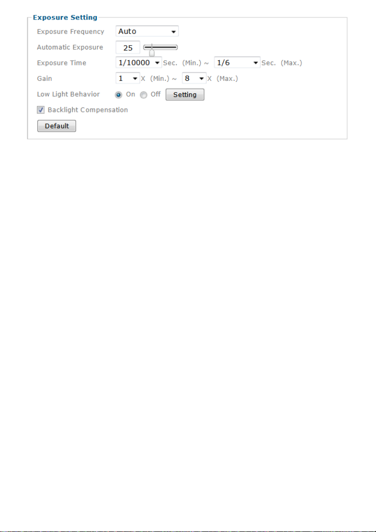
Exposure Frequency:
Current.”
If your camera is installed so that it’s facing outside, you should select “Auto.”
If your camera is installed indoors, you must select the appropriate light
frequency (either 50 or 60 Hz; e.g., in the US select 60 Hz, in Germany, Poland
or Italy select 50 Hz). The hold current option fixes the current exposure
settings.
Automatic Exposure: You can manually set the exposure va lue, which ranges
from 0-100 (dark to bright). The default value is 25 and typically provides good
results.
Exposure Time: You can define the minimum and maximum exposure time of
the camera’s shutter here. We recommend using the smallest exposure ti me
(e.g., 1/10000 sec) for the min value as it ensures the camera will generate
crisp images during day time conditions in which even moving object s appear
sharp and in focus. As for the max value, the bigger the value, the longer the
camera keeps the shutter open in low light conditions allowing more light to fall
onto the image sensor. As a result, the camera can capture image s even in
very dark environments. The downside is that moving objects will appear
blurred as the move while the camera’s shutter is open.
Gain: The Intellinet camera is equipped with an electronic gain mechanism
which helps capture image in dark conditions. The higher the gain, the brighter
the image, but the downside is that the image con tains more noise.
Low Light Behavior: When enabled, this opens allows additional control over the
camera when it is running in night mode.
Backlight Compensation (BLC): In images where a bright light source is behind
the subject of interest, the subject would normally appear in silhouette. BLC
allows the camera to adjust the exposure of the entire image to properly
expose the subject in the foreground. The resulting image may appear
overexposed in the background; however, the object of interest is now properly
lit.
There are four values: “Auto,” “50Hz,” “60Hz” and “Hold
- 48 -
Page 49

Some Intellinet network cameras are equipped with a motorized iris. In optics,
an iris is a thin opaque structure with an opening (aperture) at its center. The
role of the diaphragm is to stop the passage of light, except for the light
passing through the aperture. “Open” ensures that the iris stays always open,
regardless of the amount of light present. In situations where the light levels
vary over time greatly (i.e. day time – night time – day time, etc.), using
“Auto” is the preferred choice.
WDR stands for Wide Dynamic Range and allows the Intellinet network camera
to capture video in areas with high contrasting objects; e.g., extremely brigh t
and extremely dark. In a normal camera, if an object in a darker area of the
image frame is next to a bright area — for example, a person in a shadow is
next to an area with bright sunlight — then the person in the shadow would be
very dark to the point of becoming indistinguishable from the background. The
human eye, by contrast, can handle these differences much better. With WDR,
the dynamic range of the camera is greatly enhanced. As a result, you can now
clearly see the person in the shadow while the rest of the frame is still correctly
exposed, just as if it was seen through the human eye. Activate WDR by setting
it to “Auto” and then adjust the level that controls the amount of WDR
enhancement.
Your Intellinet camera features a noise reduction algorithm, which helps reduce
the graining in the video, which occurs under low light conditions. Set this
parameter to “Night Mode” to only activate noise reduction when the camera is
operating in night mode. You can also sele ct “Schedule”, “On” (activates noise
reduction permanently) or “Off” (deactivated noise reduction permanently).
- 49 -
Page 50
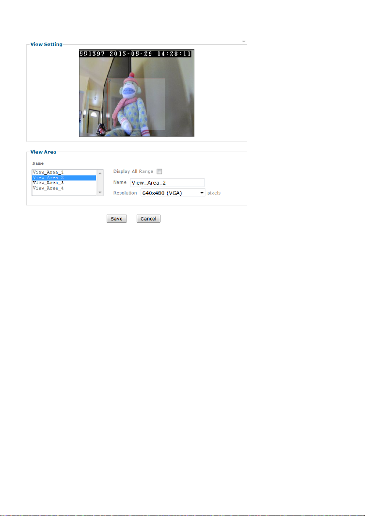
Camera Settings – View Settings
A view area is a cropped part of the entire image. Each view area is treated as
a video source with its own video stream. There are 4 areas that can b e set up
with different resolutions. When you define a profile (section 5.2.1) you can
assign to it a view area, which you define here.
- 50 -
Page 51

5.2.3 Playback
The Intellinet network camera offers an integrated
playback feature, which allows playing back videos
from your local HDD, from a network storage server or
the optional SD storage card.
Note that video playback is limited to computer
systems running Windows and MS Internet Explorer.
Client PC
You can use the player controls on the bottom left to browse for a video on
your HDD, or to pause and stop the video. On the bottom right you can find
audio controls and the digital zoom controls, which are familiar with you from
the live video page.
Network Storage
In the event settings (see section 5.2.4) you can define a local network storage
drive (NAS) as a location for the camera to save videos. The video player allows
locating recordings quickly and conv eniently on the network storage drive and
play back the files right in your web browser.
- 51 -
Page 52
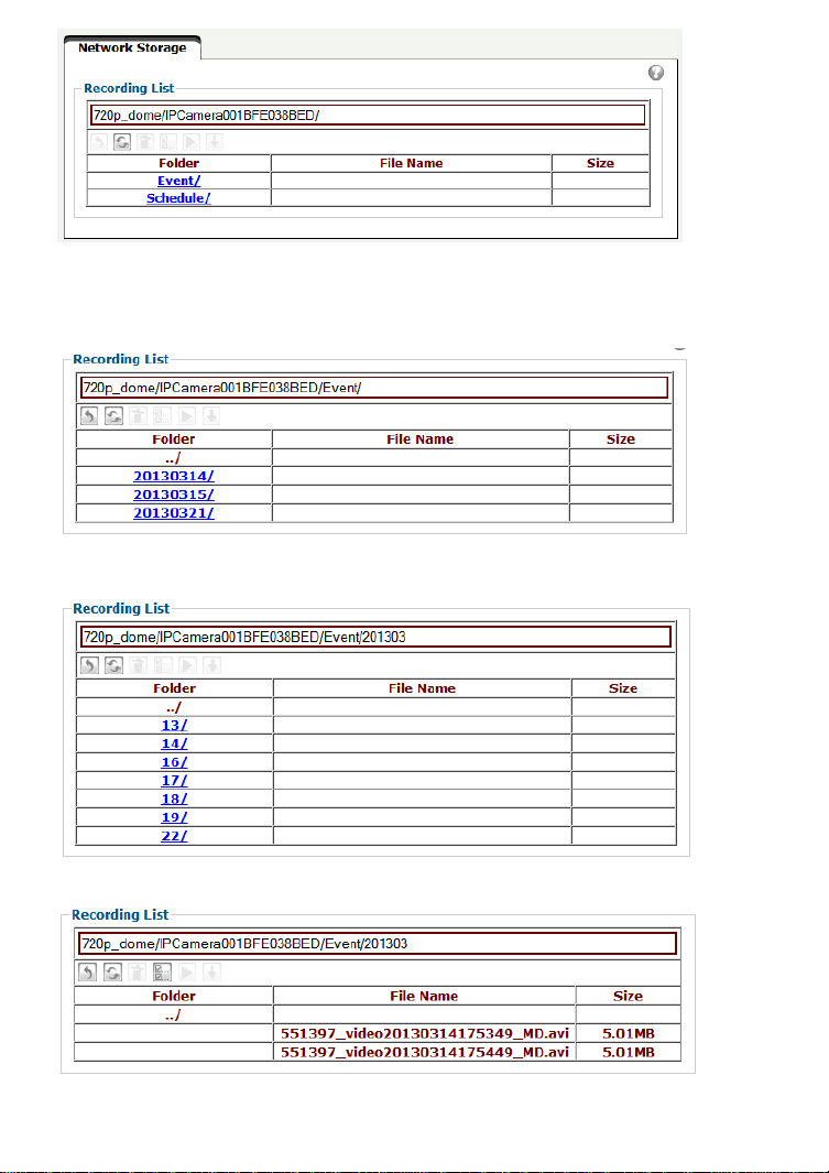
There are two folders: “Event” which is for event-triggered recordings, e.g.,
motion detection alerts, and “Schedule” which contains recordings that the
camera recorded if scheduled recording is enabled. Refer to the section 5.2.4
Event” for more details on the setup.
Above: Each day has its own folder.
Above: Each hour of the day has its own folder.
Above: Individual videos can be played back by selecting them and clicking the
play button.
- 52 -
Page 53

Above: Playback of one event recording in the web browser (MSIE only).
Item
Description
Move one folder up
Refresh the view
Delete the selected file
Select all items in the folder
Playback the selected video
Download selected item to your computer’s hard drive.
Local Storage
If your camera is equipped with a local storage option (recording on an SC
card) you can access the recordings from here. It functions similarly to the
access of files on the network storage device.
- 53 -
Page 54

5.2.4 Event
Your Intellinet network camera supports so-called events.
When an event occurs, you can have the camera perform
an action, e.g., record a video to a remote location. This
section describes how to set up event servers, events,
motion detection and the scheduler.
Event Server
First you need to set up an event server, or multiple event servers. Click “Add”
to create a new event server.
1. How to add a FTP Server:
Name: Provide a name for the server.
Server Type: Select “FTP.”
Network Address: Type in the
address of your FTP server. Do
not type in leading ftp:// or
trailing folder names.
Incorrect:
“ftp://networkipcamera.com/
camera_images”
Correct:
“networkipcamera.com”
Server Port: Leave at 21,
unless your FTP server uses a
different port.
User Name and password:
Provide valid login credentials
for the FTP server.
Passive Mode:
Select “On” if your FTP server
utilizes passive FTP, which is
the most common method.
Media Settings:
Here you define what kind of media you wish to upload (snapshot, video or
system log), how many images pre and post event you wish to up load, the
image file name and the suffix.
- 54 -
Page 55
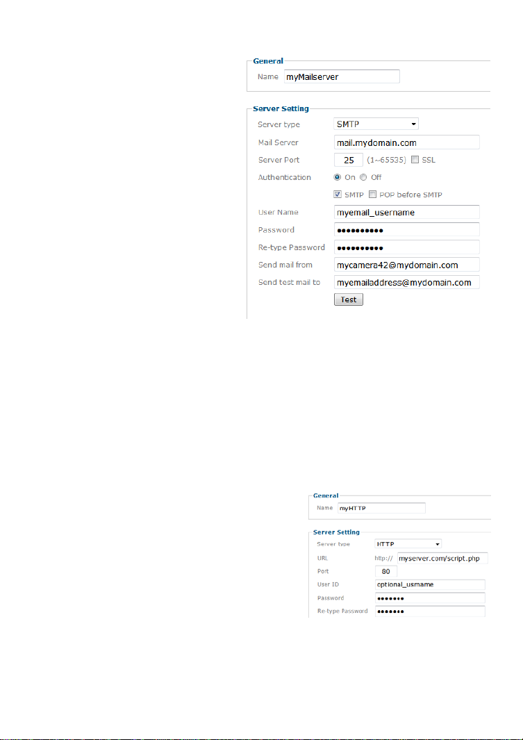
2. How to add a SMTP Server:
Server Type: Select “SMTP.”
Mail Server: Type in the address
of your mail server. Do not type in
leading smtp:// or http://.
Server Port: Adjust the server port
if necessary. Port 25 is standard,
but your server may be using
different values (not so
uncommon these days as an antispam measure).
Authentication: If your mail server
requires authentication in order to
send email, and most servers do
these days, set authentication to
“On” and define the type of
authentication below.
User Name and password:
Provide valid login credentials fo r the email server.
Send mail from: The camera will use this address as its own email address. This
email address does not necessarily need to be a valid address.
Send test email to: Enter the email address to which you want the camera to
send the images and click on Test. If the test succeeds you can provide the
information for the media settings and click “Save”. The actual target email
address is defined when you set up an event in the next se ction.
3. How to add a HTTP Server:
A HTTP server can be used by the camera to
trigger a script on a remote server if an event
occurs. User name, password and proxy fields
are all optional.
- 55 -
Page 56

4. Adding a Network Storage
Server Type: Select “Network Storage.”
Type: Select a valid type for your
network storage (either Windows
SMB or Linux NFS).
Network Storage Location:
Enter the address of your local
storage server as shown on the
right. Example:
\\192.168.0.190\media
(192.168.0.190 is the local IP
address of the network storage
server. “media” is used in the
example to indicate that we want
to upload files into the sub folder
media)
User Name and password:
Provide valid login credentials for the network storage serv er.
Create Folder: Type in a folder name in which you want the camera to store
files. This field is optional.
Media Settings: See above.
Based on the information in our example, the camera would store files in this
location:
\\192.168.0.190\media\720p_dome
SD Card
If you want to record video footage on a local
SD card, you first must insert the SD card (see
hardware installation guide for details), and
then you must set the Memory Card to “on” and
format the card by clicking “Execute.”
- 56 -
Page 57

Event List
Now that we have created an Event Server, we can proceed with setting up
actual events. Click on the “Add” button to begin.
You need to specify the trigger type. The drop-down list below shows the
available options. Note that depending on your camera model, the options will
vary.
Item
Description
Motion Detection The camera monitors the video image for movements
Tampering Detection The camera can detect if it’s being tampered with, e.g.,
Digital Input If your camera is equipped with digital inputs (see
Periodical This trigger type can be used if you want the camera to
and triggers an alert when it detects motion. Motion
detection needs to be configured first for that to work.
if someone covers the lens, and triggers an alert when
this happens. Tampering detection needs to be
configured for that to work.
hardware installation guide), then you can use them as
a trigger mechanism. A common example would be to
rd
use 3
party motion detection sensors that trigger the
camera to start a recording.
perform the same action over and over again, based on
a time period. A typical application would be to have
the camera refresh an image on your web site every 60
seconds.
- 57 -
Page 58

Onboot This is a one-time event that is triggered after the
IR Cut Filter This trigger event becomes active whenever the camera
Capacity Warning If you are using the SD Card storage option and you are
Network Link Down This trigger type activates if the camera loses
IP Notification This event is triggered when the network is being
After you have selected the tripper type, you now have to define the action(s).
In other words, what do you want the camera to do if the event occurs?
camera has restarted.
enters the night mode and has removed the IR cut
filter. For example you can have the camera send you
an email informing you about this event.
getting close to running out of storage space, this event
is being triggered. You could use this in order to send
you an email about this so that you can take
preemptive and corrective action.
connection to the network.
restarted or the IP address has changed.
- 58 -
Page 59
Item Description
Send Image Instructs the camera to send out images. When
Send Notification This action type uses the HTTP event server. You can
Activate Digital
Output
Night Mode This action type instructs the camera to activate the
selected, you need to specify whether you want to use
FTP, network storage or SD card. You may need to set
up these servers first (see previous section) in order to
use them here.
use this to have the camera trigger a script on a server.
If your camera is equipped with digital outputs (see
hardware installation guide), then you can use them to
perform an action. You can specific how long you want
the camera to trigger the event once you have selected
either Digital Output 1 or 2.
night mode.
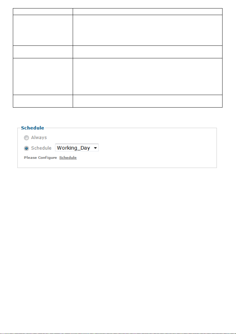
Here you can define when you want this action to be active. You can choose
between “Always” or a schedule that you have defined (see “Schedule” a few
pages down).
- 59 -
Page 60

Motion Detection
The Intellinet network camera is able to monitor the video footage for
movements and trigger an alert if motion has been detected. Th is motion
detection does not utilize passive infrared, but instead it relies on a frame by
frame comparison of the video footage the camera captures.
You can define more than one motion detection area. The example above
shows that so-called hotspot has been created for the area of the entrance
door. When you set up an event for motion detection, you can select which
motion detection area you wish to monitor.
Threshold and sensitivity will need to be set up so that you don’t miss
important events and are not flooded by false alarms either. Finding the right
values will require some trial and err or. There are no standard values that
simply “will work” as it depends very much on the actual location and light
levels. Generally speaking, increasing the sensitivity while lowering the
threshold will generate more false alarms but it ensures that you will not miss
an important event. Doing the opposite will of course have the opposite effect:
Fewer false alarms at an increased risk or missing an important event.
Tampering Detection
If the image of the camera is obstructed, e.g., becau se someone covers up the
lens or moves the image out of focus, the camera notices this and generates a
trigger alert. You can define how long you want the alert state to remain active
after the event has occurred.
- 60 -
Page 61

Schedule
The Network Camera supports event trigger actions that can be based on a
schedule. This can be used, as an example, to only activate motion detection
between 9 pm and 6 am during business days and around the clock on the
weekends. You can set up individual schedules for each event type, so that
motion detection is activated between 7 pm and 7 am, but tampering detection
is only activated between 10 pm and 4 am.
Depending on your camera model, the screen layout will vary slightly.
There are three default schedules which you cannot delete, but you can modify
them.
You can create a new schedule by clicking “Add.”
First you need to provide a name for the schedule (not shown on image). Then
select a start and end time and click on “Add” for the day of the week the
schedule is supposed to be active. As soon as you add a schedu le, the timeline
turns red, indicating the active schedule. If the schedule is the same for every
day of the week, you can activate the option “Use the same time schedule
every day.”
- 61 -
Page 62

5.2.5 System
The system menu provides access to a variety of
system settings of your Intellinet network camera.
Maintenance - Restart
You can restart the network camera by hitting the
restart button. Set Auto Restart to “On” if y ou wish to
reboot the camera automatically, and then you specify
the reboot mode. Select “Sequential mode” and specify
after how many days of uptime you want the camera to
reboot. Select “Schedule Mode” to control when the
reboot is to occur in a much more detailed way.
Maintenance - Backup/Restore
Default: Click this button to restore he factory default settings in this camera.
You can choose to exclude the IP and date & time settings.
Backup: This function allows saving the current configuration of the camera to a
file on your computer’s hard drive. Saving the configuration is useful in case
you ever want to reload a specific config uration; e.g., in order to set up another
camera of the same model and firmware version with the exact same
configuration. Since the IP address configuration is also part of the setting date,
you must be careful not to restore the same settings to two or more cameras
when all of them are connected to the same network. Otherwise, you would be
creating an IP conflict in your network.
Restore: With this function, you can reload a previously saved configuratio n
back into your camera. Click Browse to locate the configuration file and OK to
begin the process. The camera will perform a reboot at the end of the
procedure and the new settings will become effect ive.
Maintenance - Firmware Upgrade
From time to time, there will be a new firmware version available for your
camera. New firmware versions can enhance the functionality of the camera, or
they can fix problems. Before you begin, make sure that you have obtained a
proper firmware from the Intellinet Web site. If you are not 100% sure about
this, do not proceed. Instead, contact the t echnical support team to verify the
firmware version. Also, do not perform the upgrade from a computer that is
connected to the network wirelessly, as the connection is inherently less stable
than a cable-based connection. If you have the correct firmware file, make sure
that you un-compress the ZIP file first (if the firmware file is an archive) and
you end up with a file that has an extension *.bin. Click on Browse and select
the *bin file. Click on OK to begin th e upgrade process.
- 62 -
Page 63

The following message will appear:
Click “OK” to continue.
Another message will appear:
Click on “Cancel” to abort the operation. Click o n “OK” to start the upgrade
process.
You will see the following messages:
Note: You may see additional messages at this stage.
When you see this message, the upgrade has been completed. It may take up
to two minutes to re-gain access to the camera. If the camera no longer
responds, use the Windows IP Installer utility to find the camera and reconfigure the IP Address settings.
Maintenance - Language
You can replace the language in the user interface of your network camera. On
the Installation CD are different language files starting with “LNG_” and ending
with “.lang.” Click on Browse, select the language you wish to install and then
click on OK to begin the process.
- 63 -
Page 64

Date Time - Current Date / Time
Refer to section 5.2.1.
Security - Account
Refer to section 5.2.1.
Security - IP Address Filter
Once you enabled it, the listed IP address are allowed or denied access to the
network camera. Add the IP address that you’d like to allow or deny, select
allow or deny from the list and save it.
HTTPS
Secure Sockets Layer (SSL) is a cryptographic protocol that provides security
for communications over networks such as the Internet.
HTTPS is a URI scheme used to indicate a secure HTTP co nnection (SSL
encrypted). It is syntactically similar to the http:// scheme that is normally
used for accessing resources using HTTP. The differences are that SSLencrypted connections always begin with ht tps:// instead of http://. HTTPS
connections use TCP port 443 by default, compared to standard HTTP
connections, which use port 80.Create & Install: Create a self-signed certificate
for HTTPS to recognize.
Installed Certificate: Display or remove the properties of the installed
certificate.
HTTPS Connection Policy: Set HTTPS connection policy for different level of
users.
To use the HTTPS encryption, please set up “Create self-signed certificate” for
the first time you use the HTTPS function, an d then set up the connection policy
for different users.
Note: When enable HTTPS with RTSP on mode, the IP Camera only protect the
setting such as username and password and do not protect video and audio.
When enable HTTPS with RTSP off mode, the IP Camera will protect all setting
including video and audio.
Network - Basic
Refer to section 5.2.1.
- 64 -
Page 65

Network Advanced - RTSP
General
RTP Port Range: The default value of port range is 5000 ~ 7999 and can be
changed from 1124 to 65534.
RTSP Port:
RTSP stands for Real Time Streaming Protocol. RTSP is supported by most
media clients, such as Real Player, VLC and QuickTime. If you only plan to view
the camera video with your Web browser or with one of the provided software
utilities, you do not need to activate this option. The default value is 554 and
can be changed from 1124 to 65534.
RTSP Configuration
This option allows you to set up the URL for each profile and define whether or
not you want to enable or disable authentication . By default, the video URL and
profile number are related, e.g., profilex = video.prox, but you change it any
way you like. Based on the default URLs, access to the RTSP streams would be
done like this:
rtsp://camera_address:554/video.pro1
rtsp://camera_address:554/video.pro2
rtsp://camera_address:554/video.pro3
rtsp://camera_address:554/video.pro4
If authentication is enabled, the URLs will change as follows:
rtsp://username:password@camera_address:554/video.pro1
[...]
rtsp://username:password@camera_address:554/video.pro4
Multicast
Your Intellinet network camera supports multicast streaming. The differences
between multicast and unicast streaming are explained below. Note that for
most users the multicast streaming feature will not be of any importance and
most likely the required network infrastructure for proper multicast streaming is
not in place.
Unicast: For each connected computer there is a separate TCP/IP connection.
When 20 computers are connected to the camera, the camera has to create 20
different connections, and the camera has to send out the same video data to
each of the 20 computers. This not only puts
a significant load on the camera, it also
creates massive amounts of data that need
to be transferred over the network to each
connected client. Unicast is still the most
common model when using a network
camera, since most times only a recording
device (DVR or NVR) is connected to the
camera and perhaps connections from just a small number of computers.
- 65 -
Page 66
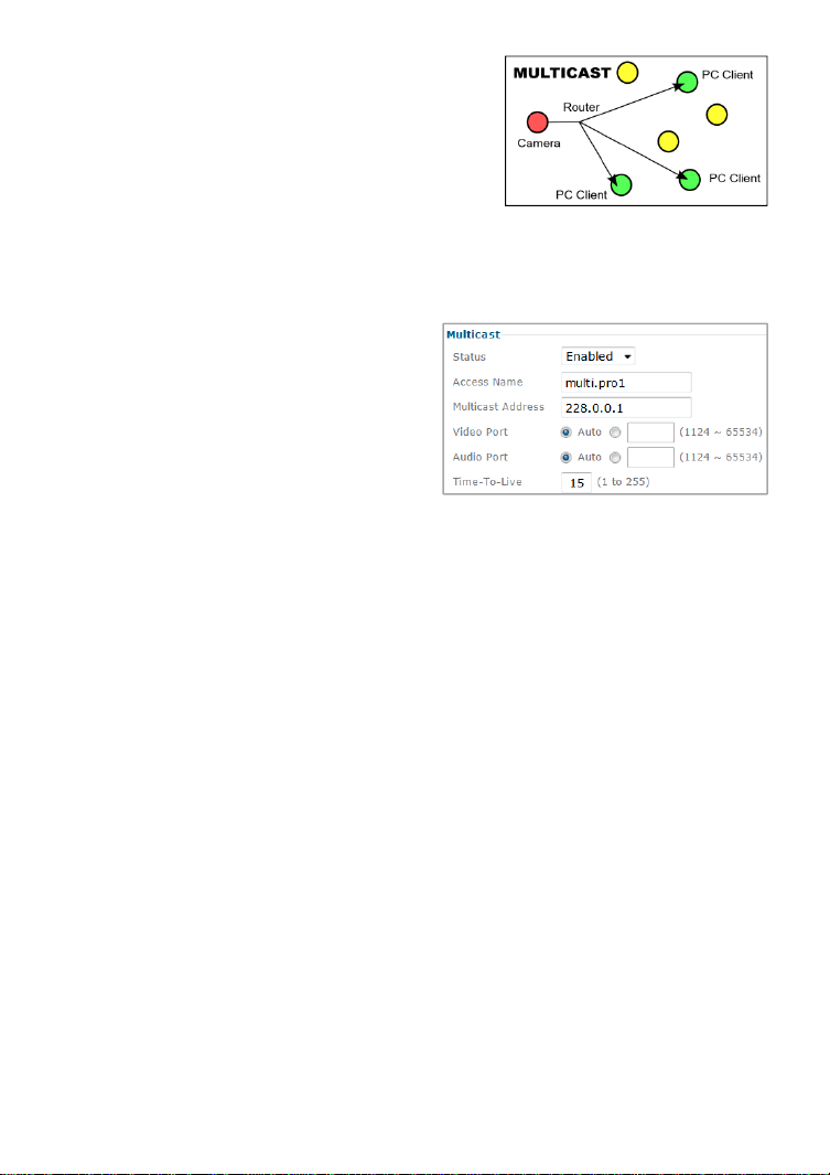
Multicast: Here the initial stre am is sent to the
router only, which creates optimal distribution
paths for datagrams sent to a multicast
destination address. Whether one or 300 PCs
are connected to the video stream does not
matter. The bandwidth and load of the local
camera is unaffected. Because of this,
multicast is the preferred choice for broadcasttype applications.
Status: Enable or disable the multicast
function here.
Access Name: This is the stream URL. It
depends on the profile selected and can
be modified.
Multicast Address: Type in the multicast
server address here.
Video / Audio Port: You can specify the
audio and video ports here, or you can
use the auto value, which should be good for most occa sions.
Time to Live: The Time-To-Live value defines how long multicast traffic will
expand across routers. Routers have a TTL threshold assigned and only
datagrams with a TTL greater than the interface's threshold are forwarded.
- 66 -
Page 67
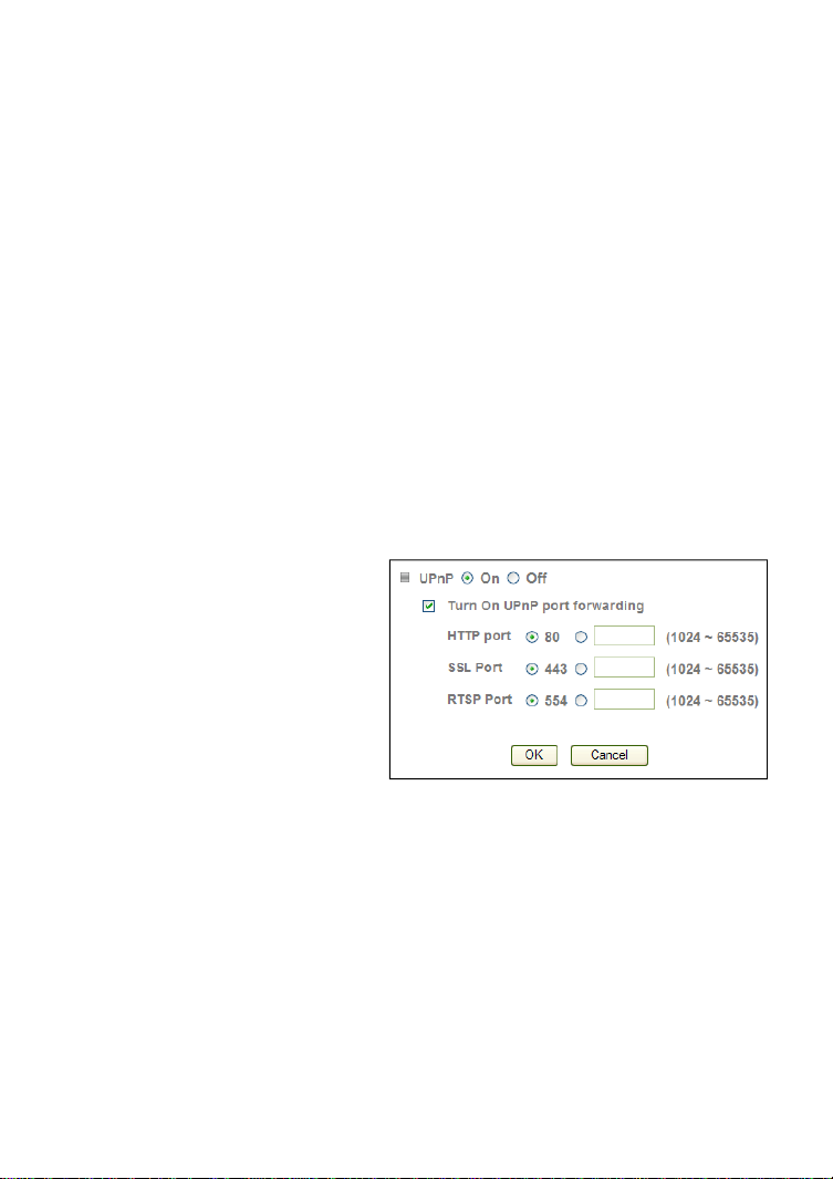
Network Advanced - UPNP
UPnP stands for Universal Plug and Play. A UPnP-enabled device, such as your
network camera, announces its presence in the local network to other
computers that support UPnP as well. The operating systems Windows XP,
Windows Vista and Windows 7/8 support UPnP. When the network camera is
connected to the network, Windows will alert the computer user of the presence
of the new device (a new icon will be added to your My Network Places folder)
and lets the user connect to the device instantaneously.
Furthermore, UPnP has the ab ility to instruct the router or firewall to open
certain ports, so that a party from the outside world can contact a device on
the local network, such as the network camera.
UPnP port forwarding is not supported by all routers, however. So, depending
on your router or firewall, you may or may not be able use this function, also,
opening ports in any router or firewall increases the risk of an intruder
successfully breaking in to your network. UPnP automates this task and leaves
it to the devices to negotiate which ports to open. Since this is done without
any form of authentication, enabling UPnP port forwarding in your router is not
necessarily a good idea in a security-sensitive environment. You can always
open individual ports in your router or firewall manually.
In the camera UPnP is enabled by default. UPnP port forwarding is disabled by
default. When you enable UPnP port forwarding, the screen will reveal
additional options. These are the ports the camera will instruct the router to
open. Depending on the camera model, you may see different ports. The new
H.264 Megapixel cameras have a
simpler port model and require
fewer ports than the other
models. Normally there is no need
to change any of these ports,
unless you know that a port is
already in use by a different
device or application.
- 67 -
Page 68

Network Advanced - Bonjour
UPnP Bonjour is a service that, just like UPnP, helps to find the network camera
on the network. Bonjour is available for Windows, but is more commonly used
for MacOS. Refer to section “4.1.2 MacOS” for additional information on the
usage.
Bonjour:
On: Enables the service (on by default).
Off: Disables the service
Device name:
Enter the name of your
camera here. This is the
name the Bonjour service
will display. If you have
more than one camera
installed in your network,
this is an easy way to
differentiate among the
cameras.
Network Advanced - DDNS
If you are not planning on connecting to the network camera over a remote
connection, but only in your local network, you can skip this section.
Dynamic DNS is a network service that provides the capability for a networked
device, such as a router or computer system, to notify a domain name server to
change, in real time (ad-hoc) the active DNS configuration of its configured
host names, addresses or other information stored in DNS.
In simpler terms: Users of private Internet services are often faced with a
problem: The ISP typically changes the IP address assigned to the user based
on a time interval. This may be as often as once every 24 hours or as seldom
as once every 30 days. For the average user this is not a problem. However, if
you want to be able to connect to the local camera (e.g., in your house) fr om a
remote location (e.g., the office), you need to know under which Internet
address the camera can be reached. However, you don’t know what the current
Internet IP address is. So you are beginning to see the problem.
DDNS solves this problem by allow ing y ou to create a domain name for your
home network, which you can always use to access the camera. To use the
DDNS function, you will need to do the fo llowing two things.
1. Create a DDNS hostname with a DDNS service provider
2. Set up a DDNS client in the home network that contacts the DDNS service
provider and updates the IP information.
- 68 -
Page 69

If the router in your home network is equipped with a DDNS client, we
recommend using the router instead of the camera. Most SOHO routers are
equipped with a DDNS client and since the router is in direct control of handling
the Internet connection, it’s the device best suited for the DDNS task.
Server Name: Select the DDNS provider of your choice. In our example we use
no-ip.com.
User ID: Enter the same user name here that you use to log in to your account
settings on www.dyndns.org. Do not enter your DSL user account information
here.
Password: Enter the password for your no-ip.com user account here. Re-type
the password in the field below.
Host name: You need to enter the full host name that you have created in your
no-ip.com account here.
Periodic Update: You can either specify the time in minutes after which the
camera will update its IP information with the DDNS provider, or you can leave
the setting as “Auto”, which is recommended.
Click “Save” to activate the settings. Reboot the camera to activate the DDNS
settings. After a reboot you may need to wait for a few minutes before you can
access the camera with the new domain n a me.
- 69 -
Page 70

Digital I/O
If your Intellinet network camera is equipped with a digital I/O interface, you
can configure the connections on this page. The s creen shows the current
status of input 1 & 2 and output 1 & 2. The screen also allows you to define the
“normal” state of the port. The normal state can be viewed as the “non-alertstate.”
LED
You can enable or disable the operation LEDs on your Intellinet network
camera. Hiding the LED indicator will make the camera appear to be offline
while in fact it is operational and captures video.
- 70 -
Page 71

System Log
The Network Camera features a log function for system messages. These are
system messages about the camera start-up procedure, e-mail deliveries, FTP
uploads, motion detection and more. The camera stores the messages in its
internal memory and displays them on the system log screen. Since memory is
limited, the messages will eventually be truncated. If you need to log all the
system messages on a remote server (e.g., for permanent record keeping of
alarm events or for troubleshooting purposes), you can utilize the remote log
functionality.
Enable remote log: Server name: Type in the netw ork address of the Syslog
server. Enter the address without any leading characters,
such as http://.
Server port: The standard port for this protocol is 514. If
your Syslog server is set up differently, you can change the
value here.
Current log: This text box displays the real-time log of the camera
messages.
- 71 -
Page 72

The remote log function uses the Syslog
Protocol, which is a standard for forwarding
log messages in an IP network. Syslog is a
client/server protocol. The Syslog sender (the
Network Camera) sends a small (less than
1KB) textual message to the Syslog server.
This user manual shows one example of a
Syslog server, the 3CDaemon utility by 3Com Corporation (Download Location:
http://support.3com.com/software/utilities_for_windows_32_bit.htm).
After the installation of 3CDaemon, the main program window opens and the
program is ready to receive Syslog messages from the network camera.
The messages shown here are the same messages t hat are displayed in the
Web browser.
- 72 -
Page 73

6: Video Surveillance Software
6.1 Function
Description
The Intellinet Network Camera
ships with a surveillance
application that can monitor
and record up to 16 network
cameras.
You can record video
permanently or based on a
schedule, or you can use the
integrated motion detection
function and only record
motion events to preserve disk
space. You can select from
nine different templates to display the camera images on one screen.
6.2 Installation
The program installs by clicking the
option “Video Surveillance Software”
from the CD menu.
A detailed user manual is located on
the Installation CD in the User
Manuals folder. It contains installation
instructions and information on the
use of the software.
- 73 -
Page 74

7: Questions and Answers
9.1 Accessing the Camera
What are the camera’s default IP address, administrator user name and
Q:
password?
A: The camera obtains an IP address from a DH CP server in your network. If
no DHCP server is present, the camera reverts back to its default IP
address 192.168.1.221. The default administrator user name is “admin”;
the default password is “admin.”
Q: The IP Installer utility does not show the Network Camera, even though the
camera is connected to the network. Why?
A: 1: IP Installer utilizes UPnP in order to detect the camera. Check and make
sure that UPnP support is enabled in the camera. Activate UPnP suppor t in
the settings menu under Basic -> Network -> UPnP
2: The firewall on your computer may be blocking IP Installer and is
therefore preventing it from detecting the camera. Be sure to run the
application while logged in to the computer with administra tor rights.
Q: IP Installer still cannot find the camera. How can I find it on the network?
A: 1: If a DHCP server is present on the network (e.g., a router), you can
check the DHCP server’s client log after you have connected the camera to
the network. The camera will show up in the log, typically with the highest
of the IP addresses shown, as DHCP servers assign IP address es in
sequence (newest client with newest I P address).
2: If the camera is not connected to a DHCP server, or if you connect the
camera so that it is isolated from the rest of the network, you can connect
to the camera at its default IP address of 192.168.1.221. You may have to
adjust the TCP/IP settings of your computer manually to be in range of
192.168.1.xxx in order to gain access to the camera. Connect to the
settings menu with your Web browser and change the IP address of the
camera manually.
Q: How do I install the camera on a Mac or Linux system?
A: Refer to sections 4.1.2 and 4.1.3 in this user manual.
Q: After changing the camera's Web server port from 80 to a different value,
access to the camera is no longer po ssible.
- 74 -
Page 75

A: Whenever you change the Web server port from the standard 80 to a
different value, you need to append the port to the camera's IP address.
The syntax is always http://cameraip:portnumber.
Example: When you change the Web server port to 81, the correct address
would be: http://192.168.1.221:81.
Q: I changed the HTTP port in the camera settings, but after I saved the
settings the camera still responds on the old HTTP port. The new value is
ignored.
A: After changing the HTTP port in the Basic->Network->Information screen
and saving the settings, you need to reboot the Network Camera. You can
either temporarily cut the power to the ca mera, or you can reboot the
camera via the settings menu (Basic->System->Initialize).
9.2 Web Browser Access
I cannot use some of the features of the Network Camera. For example, I
Q:
cannot set up motion detection or record video from the live video page.
A: Only MS Internet Explorer supports full access to all functions. Refer to
section 2.3 for a list of limitations for other Web browsers, such as Firefox,
Opera or Safari.
Q: I am using MS Internet Explorer, but when I connect to the camera I don’t
see a live image.
A: When you first connect to the cam era with MSIE, you need to install an
ActiveX control. If your Internet security settings do not allow the
execution of signed ActiveX controls, or if you do not run MSIE while
logged in to the system as a computer administrator, the installation of the
ActiveX control will be prevented. Check the Internet options and make
sure you are running MSIE as a computer administrator. Subsequent
connections can be made without administrator righ ts.
- 75 -
Page 76

9.3 Camera Related Issues
The camera does not send any e-mails. Why?
Q:
A: 1. The problem occurs because the camera cannot contact the e-mail
server. Check:
- Is the e-mail (SMTP) server address correct?
- Did you specify the correct gateway IP address?
- Did you specify correct DNS servers?
- Did you enter the correct e-mail address?
- Did you specify the e-mail title?
2. The e-mail server denies the delivery request from the camera.
Check:
- Is a valid sender address specified?
- Did you activate SMTP authentication?
- Did you enter the correct user name and password for SMTP
authentication?
Also be sure to have the latest firmware installed in case you experience
difficulties. Possible compatibility problems are likely to be resolved in
newer firmware versions.
Q: Can I use the camera' s integrated motion detection function to secure
sensitive areas and goods of a high value?
A: Using the Network Camera's integrated motion detection for securing high-
value items is not recommended, as the function does not work as reliably
as professional security sensors.
We recommend using professional security monitoring soft ware in
combination with the Network Camera. You may also connect external
security sensors to the camera's digital input port for increased security.
- 76 -
Page 77

Q: Does my camera support PoE (Power over Ethernet)?
A: The following models support PoE:
- IBC-607IR Network Bullet Camera
- IBC-637IR HD Network Bullet Camera
- IBC-667IR HD Network Bullet Camera
- IDC-832 HD Mini Network Dome
- IDC-862 HD Mini Network Dome
- IDC-752IR HD Network Dome
- IDC-757IR HD Network Dome
- IDC-767IR HD Network Dome
- NFD130-IR HD Network Dome
- NFD130-IRV HD Network Dome
- 77 -
Page 78

Intellinet™ offers a complete line
of active and passive networking products.
Ask your local computer dealer for more information or visit
www.intellinet-network.com
Copyright © Intellinet
All products mentioned are trademarks or registered trademarks of their
respective owners.
- 78 -
 Loading...