

Page 1
PoE+ DESKTOP SWITCH
USER MANUAL
MODELS 560757 & 560764
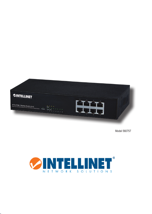
Model 560757
intellinet-network.com
Important: Read before use. • Importante: Leer antes de usar.
INT-560757/560764-UM-ML1-0114-02
Page 2
PoE+ Desktop Switch • User Manual English
CONNECTIONS & INDICATORS
PoE
POWER LINK / ACT
1 2 3 4 5 6 7 8
LEDs
The LED indicators — Power,
PoE, Link/Activity — make it
easier to monitor the switch
and its connections. NOTE:
On Model 560757 (above,
with just four PoE LEDs), only
Ports 1-4 can provide power
to a connected device; all powered devices should also comply with IEEE 802.3af.
Ports
All ports on the switch support Auto-MDI/MDI-X functionality, so crossover cables and uplink
ports are not needed for connections to PCs, routers, hubs, other switches, etc. Cat5/5e/6
UTP/STP cables provide optimal performance; if a status LED doesn’t indicate a link or activity,
check the corresponding device for proper setup and operation.
Power
Use the power cord to connect the power adapter (both included)
to the DC 48V power jack on the rear panel. Then plug the
adapter into an AC outlet and conrm that the power LED is
lit. NOTE: For proper operation, use only the included power
adapter.
LED Status Operation
PWR On Power on
O Check the AC connection; turn the power on
PoE On Port is linked to a PSE/PoE device
O No PSE/PoE device is linked
LNK/ACT On Valid port connection
Blinking Valid port connection; data transmitted/received
O No link established
8 RJ45 10/100M ports
2 4 6 8
1 3 5 7
INSTALLATION
Prior to use, it is recommended that the switch be placed/positioned:
• on a level surface with at least 25 mm (approx. 1”) of clearance for ventilation;
• away from sources of electrical noise: radios, transmitters, broadband ampliers, etc.;
• within 100 m (approx. 328’) of network devices it’s to be connected to.
2
ENGLISH
Page 3
PoE+ Desktop Switch • Handbuch Deutsch
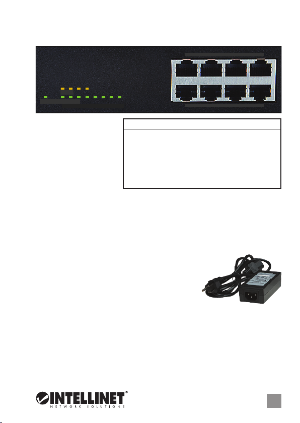
ANSCHLÜSSE & ANZEIGEN
PoE
POWER LINK / ACT
1 2 3 4 5 6 7 8
8 RJ45 10/100M Ports
2 4 6 8
1 3 5 7
LED-Anzeigen
Die LEDs — Strom, PoE,
Verbindung/Aktivität —
vereinfachen das Ablesen der
Funktionen und Anschlüsse.
HINWEIS: Beim Modell 560757
(siehe oben, nur 4 PoE-LEDs),
können nur die Ports 1-4
LED Status Operation
POWER An Gerät wird mit Strom versorgt
Aus Stromanschluss prüfen/Gerät einschalten
PoE An Port ist mit PSE/PoE-Gerät verbunden
Aus Kein PSE/PoE-Gerät angeschlossen
LINK/ACT An Verbindung ist hergestellt
Blinkend Verbindung ist hergestellt; Datenübertragung
Aus Verbindung ist nicht hergestellt
angeschlossene Geräte mit Strom versorgen; diese sollten mit IEEE 802.3af kompatibel sein.
Ports
Alle Ports unterstützen Auto-MDI/MDI-X Funktionalität, daher werden Crosskabel und UplinkPorts für Verbindungen zu PCs, Routern, Hubs, anderen Switchen, etc. nicht benötigt.
Cat5/5e/6 UTP/STP-Kabel bieten die beste Performance. Wenn eine LED keine Verbindung/
Aktivität anzeigt, überprüfen Sie das verbundene Gerät.
Strom
Schließen Sie das Netzteil per Stromkabel (beides im Lieferumfang)
an die DC 48-Buchse auf der Rückseite an, dann den Stecker an der
Steckdose. Prüfen Sie, ob die “Power”-LED aueuchtet.
HINWEIS: Nutzen Sie nur das mitgelieferte Netzteil für
optimalen Betrieb.
INSTALLATION
Es wird empfohlen, den Switch vor der Nutzung folgendermaßen aufzustellen:
• auf ebenem Untergrund mit mind. 25 mm Rundumabstand für ausreichend Luftdurchsatz
• fern von anderen Übertragungsgeräten wie Radio, Breitbandverstärker, etc.
• max. 100 m vom zu verbindenden Netzwerkgerät entfernt.
DEUTSCH
3
Page 4
Switch PoE+ para Escritorio • Manual del usuario Español
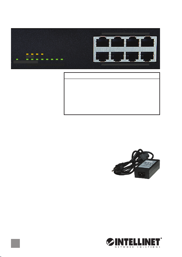
CONEXIONES E INDICADORES
PoE
POWER LINK / ACT
1 2 3 4 5 6 7 8
LEDs
Los LEDs — Power, PoE Link/
Activity — hacen mas facil
monitorear el switch y sus
conexiones. NOTA: En el Modelo
560757 (arriba, con solo cuatro
LEDs PoE), solo puede proveer
energia a un dispositivo; todos
los dispositivos a energizar deben cumplir con IEEE 802.3af.
Puertos
Todos los puertos del switch soportan Auto-MDI/MDI-X, los cables crossover y puertos de
enlace no son necesarios para las conexiones para PCs, routers, hubs, otros switches, etc. los
cables Cat5/5e UTP/STP proporcionan un redimiento optimo; Si un LED no indica conectividad
o actividad, compruebe las conexiones sean adecuadas.
Alimentación
Utilice el cable de alimentación para conectar el adaptador de
corriente (ambos incluidos) a la toma de CC 48V en el panel
trasero. Luego enchufe el adaptador a una toma de CA y
conrme que el LED esta encendido. NOTA: Para un
funcionamiento correcto, utilice solo el adaptador de corriente incluido.
LED Estado Operación
POWER Encendido Encendido
Apagado Revise la conexión AC; encienda de nuevo
PoE Encendido Puerto vinculado a un dispositivo PSE/PoE
Apagado No hay un dispositivo PSE/PoE conectado
LINK/ACT Encendido Valide el puerto de conexión
Parpadeo Datos trasmitidos/recibidos
Apagado No hay comunicación
8 RJ45 10/100M puertos
2 4 6 8
1 3 5 7
INSTALACIÓN
Antes de utilizarlo, se recomienda que el switch sea ubicado/jado:
• sobre una supercie plana con al menos 25 mm de espacio libre para ventilación;
• lejos de fuentes de ruido: radios, transmisores, amplicadores de banda ancha, etc.;
• dentro de los 100 m (aprox. 328’) deben estar conectados los dispositivos de red.
4
ESPAÑOL
Page 5

Commutateur en boîtier externe PoE+ • Manuel de l’utilisateur Français
CONNEXIONS & INDICATEURS
PoE
POWER LINK / ACT
1 2 3 4 5 6 7 8
Les DEL
Les voyants d’état — Alimentation,
PoE, Connexion/Activité —
simplient lire les fonctions et les
connexions. NOTE: Au modèle
560757 (cf. ci-dessus, avec
seulement 4 DEL PoE), seulement
les ports 1-4 peuvent alimenter des
appareils connectés, qui devraient être compatibles avec IEEE 802.3af.
Les ports
Tous les ports de ce commutateur prennent en charge la fonctionnalité Auto-MDI/MDI-X, donc
des câbles croisés et des liaisons montantes ne sont pas nécessaires pour des connections aux
PC, routeurs, etc. Des câbles Cat5/5e UTP/STP garantissent des performances optimales; si un
DEL n’indique pas d’activité, vériez l’appareil correspondant.
Secteur
Connectez l’adaptateur secteur à la prise femelle de l’appareil et
à une prise courante. Assurez-vous que le DEL est allumé.
REMARQUE: Utilisez uniquement l’adaptateur secteur et le
câble fournis avec ce commutateur pour un service optimal.
DEL État Description
POWER Allumé Appareil est alimenté
Éteint Vériez l’alimentation/Allumez l’appareil
PoE Allumé Port est connecté à un appareil PSE/PoE
Éteint No PSE/PoE device is linked
LINK/ACT Allumé Connexion est établie
Clignotant Connexion est établie; données sont transmises
Éteint Connexion n’est pas établie
8 ports RJ45 10/100M
2 4 6 8
1 3 5 7
INSTALLATION
Avant d’utiliser le commutateur, il est recommandé de le placer:
• sur une surface plane avec un écartement de 25 mm d’autres objets pour la ventilation
• loin des appareils électriques qui peuvent être source d‘interférence (des radios etc.)
• pas plus loin que 100 m de l’appareil réseau auquel vous voudriez connecter.
FRANÇAIS
5
Page 6

Przełącznik PoE+ Desktop • Instrukcja użytkownika Polski
PANEL PRZEDNI URZĄDZENIA
PoE
POWER LINK / ACT
1 2 3 4 5 6 7 8
Diody
Diody sygnalizacyjne LED dla
funkcji zasilania, PoE, link/
aktywności ułatwiają
monitorowanie przełącznika i
jego połączeń. UWAGA: W
modelu 560757 (powyżej, tylko
z czterema diodami PoE), tylko porty 1-4 mogą zasilać podłączone do przełącznika urządzenia
obsługujące standard IEEE 802.3af.
Porty
Wszystkie porty przełącznika obsługują auto-krosowanie MDI/MDI-X, więc kabel krosowany
oraz port uplink nie jest wymagany do połączenia z komputerami, routerami, czy innymi
przełącznikami. Kable Cat5/5e/6 UTP/STP zapewniają optymalną wydajność; jeśli diody
statusu nie sygnalizują linku lub aktywności, sprawdź podłączone urządzenie pod kątem
poprawności konguracji oraz jego zasilania.
Zasilanie
Podłącz kabel zasilający do adaptera zasilania (kabel i adapter w
zestawie), a następnie adapter podłącz do gniazda jack DC 48V
na tylnym panelu urządzenia. Kabel zasilający podłącz do
gniazda sieciowego oraz sprawdź status diod. UWAGA: Dla
prawidłowego funkcjonowania urządzenia, należy używać tylko zasilacza z zestawu.
Dioda Status Objaśnienie
POWER On (wł.) Urządzenie włączone
O (wył.) Sprawdź, czy zasilanie jest podłączone; włącz urządzenie
PoE On (wł.) Port jest połączony z urządzeniem PoE
O (wył.) Nie ma połączenia z urządzeniem PoE
LINK/ACT On (wł.) Prawidłowe podłączenie portu
Migająca
O (wył.) Nie nawiązano połączenia
8 portów RJ45 10/100M
2 4 6 8
1 3 5 7
Prawidłowe podłączenie portu; transmisja/odbiór pakietów
INSTALACJA
Zaleca się, aby urządzenie w trakcie użytkowania było umiejscowione:
• dla zapewnienia dobrej wentylacji w odległości co najmniej 25 mm obudowy urządzenia
od podłoża, na którym się znajduje;
• z dala od źródeł zakłóceń elektrycznych: radia, nadajnik, itp.;
• w odległości do 100 m od innych urządzeń sieciowych, z którymi bezpośrednio jest połączony.
6
POLSKI
Page 7

Switch PoE+ Desktop • Manuale d’istruzione Italiano
CONNESSIONI E INDICATORI
PoE
POWER LINK / ACT
1 2 3 4 5 6 7 8
LED
Gli indicatori LED – Power, PoE,
Link/Activity – permettono di
monitorare facilmente lo switch
e le sue connessioni. NOTA:
Per il modello 560757 (con solo
quattro LED PoE), solamente le
porte 1-4 possono fornire l’alimentazione ad una periferica connessa; tutte le periferiche
alimentate dovrebbero essere conformi allo standard IEEE 802.3af.
Porte
Tutte le porte dello switch supportano la funzionalità Auto-MDI/MDI-X, così cavi incrociati e
porte uplink non sono necessarie per connessioni a PC, router, hub, altri switch, etc. I cavi Cat5/
5e/6 UTP/STP forniscono ottimali prestazioni; se il LED di stato non indica una connessione o
un’attività, vericare la corrispondente periferica per un corretto settaggio e funzionamento.
Alimentazione
Utilizzare il cavo di alimentazione per collegare l’alimentatore
(entrambi inclusi) alla presa di alimentazione DC 48V sul pannello
posteriore. Quindi inserire la spina dell’alimentatore nella
presa di corrente AC e vericare che il LED dell’alimentazione
è illuminato. NOTA: Per un corretto funzionamento, utilizzare
solamente l’alimentatore incluso.
LED Stato Operazione
POWER Accesso Accesso
Spento Vericare la connessione AC; accendere l’apparecchio
PoE Accesso Porta collegata alla periferica PSE/PoE
Spento Nessuna periferica PSE/PoE è collegata
LINK/ACT Accesso Porta di connessione valida
Lampeggiante Porta di connessione valida; trasmissione/ricevimento dati
Spento Nessuna connessione stabilita
8 porte RJ45 10/100M
2 4 6 8
1 3 5 7
INSTALLAZIONE
Prima dell’uso, si raccomanda che lo switch venga posizionato:
• su una supercie piana con almeno 25 mm di spazio libero per una corrette ventilazione
• lontano da fonti di disturbo elettrico: radio, trasmettitori, amplicatori a banda larga, etc.;
• entro 100 m dalle periferiche di rete a cui è stato connesso.
ITALIANO
7
Page 8

WASTE ELECTRICAL & ELECTRONIC EQUIPMENT
(applicable in the European Union and other European countries with separate collection systems)
ENGLISH
This symbol on the product or its packaging indicates that this product shall not be treated as household waste.
detailed information about recycling of this produc t, contact your local city oce, your household waste
disposal service or the shop where you purchased this product. In countries outside of the EU: If you wish
to dis card this product, contact your local authorities and ask for the correct manner of disposal.
DEUTSCH
Dieses auf dem Produkt oder der Verpackung angebrachte Symbol zeigt an, dass dieses Produkt nicht mit
dem Hausmüll entsorgt werden darf. In Übereinstimmung mit der Richtlinie 2002/96/EG des Europäischen
Parlaments und des Rates über Elektro- und Elektronik-Altgeräte (WEEE) darf dieses Elektrogerät nicht
im normalen Hausmüll oder dem Gelben Sack entsorgt werden. Wenn Sie dieses Produkt entsorgen
möchten, bringen Sie es bitte zur Verkaufsstelle zurück oder zum Recycling-Sammelpunkt Ihrer Gemeinde.
ESPAÑOL
Este símbolo en el producto o su embalaje indica que el producto no debe tratarse como residuo doméstico.
De conformidad con la Directiva 2002/96/CE de la UE sobre residuos de aparatos eléctricos y electrónicos
(RAEE), este producto eléctrico no puede desecharse con el resto de residuos no clasicados. Deshágase
de este producto devolviéndolo a su punto de venta o a un punto de recolección municipal para su
reciclaje.
FRANÇAIS
Ce symbole sur Ie produit ou son emballage signie que ce produit ne doit pas être traité comme un
déchet ménager. Conformément à la Directive 2002/96/EC sur les déchets d’équipements électriques
et électroniques (DEEE), ce produit électrique ne doit en aucun cas être mis au rebut sous forme de
déchet municipal non trié. Veuillez vous débarrasser de ce produit en Ie renvoyant à son point de
vente ou au point de ramassage local dans votre municipalité, à des ns de recyclage.
ITALIANO
Questo simbolo sui prodotto o sulla relativa confezione indica che il prodotto non va trattato come un riuto
domestico. In ottemperanza alla Direttiva UE 2002/96/EC sui riuti di apparecchiature elettriche ed
elettroniche (RAEE), questa prodotto elettrico non deve essere smaltito come riuto municipale misto. Si
prega di smaltire il prodotto riportandolo al punto vendita o al punto di raccolta municipale locale per un
opportuno riciclaggio.
POLSKI
Jeśli na produkcie lub jego opakowaniu umieszczono ten symbol, wówczas w czasie utylizacji nie wolno
wyrzucać tego produktu wraz z odpadami komunalnymi. Zgodnie z Dyrektywą Nr 2002/96/WE w sprawie
zużytego sprzętu elektrycznego i elektronicznego (WEEE), niniejszego produktu elektrycznego nie wolno
usuwać jako nie posortowanego odpadu komunalnego. Prosimy o usuniecie niniejszego produktu
poprzez jego zwrot do punktu zakupu lub oddanie do miejscowego komunalnego punktu zbiórki
odpadów przeznaczonych do recyklingu.
8
Disposal of Electric and Electronic Equipment
Instead, it should be taken to an applicable collection point for the recycling of electrical and
electronic equipment. By ensuring this product is disposed of correctly, you will help prevent
potential negative consequences to the environment and human health, which could otherwise
be caused by inappropriate waste handling of this product. If your equipment contains easily
removable batteries or accumulators, dispose of these separately according to your local
requirements. The recycling of materials will help to conserve natural resources. For more
Page 9

WARRANTY INFORMATION
ENGLISH:
For warranty information, go to intellinet-net work.com/warranty.
DEUTSCH:
Garantieinformationen nden Sie unter intellinet-network.com/warranty.
ESPAÑOL:
Si desea obtener información sobre la garantía, visite intellinet-network .com/warranty.
FRANÇAIS:
Pour consulter les informations sur la garantie, visitez intellinet-network.com/warrant y.
POLSKI:
Informacje dotyczące gwarancji znajdują się na stronie intellinet-network.com/warrant y.
ITALIANO:
Per informazioni sulla garanzia, accedere a intellinet-network.com/warranty.
En México: Póliza de Garantía Intellinet — Datos del importador y responsable ante el consumidor
IC Intracom México, S.A.P.I. de C.V. • Av. Interceptor Poniente # 73, Col. Parque Industrial La Joya, Cuautitlán
Izcalli, Estado de México, C.P. 54730, México. • Tel. (55)1500-4500
La presente garantía cubre este producto por 3 años contra cualquier defecto de fabricación en sus
materiales y mano de obra, bajo las siguientes condiciones:
1. Todos los productos a que se reere esta garantía, ampara su cambio físico, sin ningún cargo para
el consumidor.
2. El comercializador no tiene talleres de servicio, debido a que los productos que se garantizan no
cuentan con reparaciones, ni refacciones, ya que su garantía es de cambio físico.
3. La garantía cubre exclusivamente aquellas partes, equipos o sub-ensambles que hayan sido instaladas
de fábrica y no incluye en ningún caso el equipo adicional o cualesquiera que hayan sido adicionados
al mismo por el usuario o distribuidor.
Para hacer efectiva esta garantía bastará con presentar el producto al distribuidor en el domicilio donde
fue adquirido o en el domicilio de IC Intracom México, S.A.P.I. de C.V., junto con los accesorios contenidos
en su empaque, acompañado de su póliza debidamente llenada y sellada por la casa vendedora
(indispensable el sello y fecha de compra) donde lo adquirió, o bien, la factura o ticket de compra
original donde se mencione claramente el modelo, número de serie (cuando aplique) y fecha de
adquisición. Esta garantía no es válida en los siguientes casos: Si el producto se hubiese utilizado
en condiciones distintas a las normales; si el producto no ha sido operado conforme a los instructivos
de uso; o si el producto ha sido alterado o tratado de ser reparado por el consumidor o terceras
personas.
North & S outh Americ a
IC Intracom Americas
550 Commerce Blvd.
Oldsmar, FL 34 677
USA
All tr ademarks and trade na mes are the prop erty of thei r respec tive own ers.
Alle Marken und Markennamen sind Eigentum Ihrer jeweiligen Inhaber.
Todas las marcas y nombres comerciales son propiedad de sus respectivos dueños.
Toutes les ma rques et no ms commercia ux sont la propr iété de leurs propriétai res respectifs.
Tutti i marchi reg istrati e le dom inazio ni commer ciali son o di propriet à dei loro rispettivi propri etari.
Wszyst kie znak i towarowe i naz wy handlowe należą do ich właścicieli.
Asia & Afr ica
IC Intraco m Asia
Far Easter n Technology Cent er
7-F No. 125, Sect ion 2, Da Tong Rd.
Shijr, Taipei
Taiwan, ROC
Europe
IC Intracom Europe
Löhbach er Str. 7
D-58553 Halver
Germany
9
Page 10

REGULATORY STATEMENTS
This equipment has been tested and found to comply with the limits for a Class A digital device,
pursuant to Part 15 of the Federal Communications Commission (FCC) Rules. These limits are
designed to provide reasonable protection against harmful interference when the equipment
is operated in a commercial environment. This equipment generates, uses and can radiate radio
frequency energy, and if not installed and used in accordance with the instruction manual may
cause harmful interference to radio communications. Operation of this equipment in a residential
area is likely to cause harmful interference, in which case the user will be required to correct
the interference at his own expense. Any changes or modications made to this equipment without
the approval of the manuafacturer could result in the product not meeting the Class A limits, in
which case the FCC could void the user’s authority to operate the equipment.
ENGLISH
This device complies with the requirements of R&TTE Directive 1999/5/EC. The Declaration of
Conformity for this product is available at:
DEUTSCH
Dieses Gerät enspricht der Direktive R&TTE Direktive 1999/5/EC. Die Konformitätserklärung für
dieses Produkt nden Sie unter::
ESPAÑOL
Este dispositivo cumple con los requerimientos de la Directiva R&TTE 1999/5/EC. La declaración de
conformidad para este producto esta disponible en:
FRANÇAIS
Cet appareil satisfait aux exigences de la directive R&TTE 1999/5/CE. La Déclaration de Conformité
pour ce produit est disponible à l’adresset :
POLSKI
Urządzenie spełnia wymagania dyrektywy R&TTE 1999/5/EC. Deklaracja zgodności dostępna jest na
stronie internetowej producenta:
ITALIANO
Questo dispositivo è conforme alla Direttiva 1999/5/EC R&TTE La dichiarazione di conformità per
questo prodotto è disponibile al:
FCC Class A
CE / R&TTE
intellinet-network.com
10
Page 11

Page 12

Intellinet is a trademark of IC Intracom, registered in the U.S. and other countries.
© IC Intracom. All rights reserved.
 Loading...