

Page 1
WIRELESS 450N
DUAL-BAND
ADAPTER
USER MANUAL
MODEL 525275
INT-525275-UM-0412-01
Page 2

Thank you for purchasing the INTELLINET NETWORK SOLUTIONS™ Wireless
450N Dual-Band USB Adapter, Model 525275.
Capable of handling lightning-fast speeds up to 450 Mbps, this USB adapter
is ideal for high-demand applications like transferring large les, streaming
HD video, using Cloud-based programs, making VoIP calls and playing online
multiplayer games. Advanced 3T3R MIMO antenna technology ensures wireless
signal range and delity, while integrated Wi-Fi Multimedia (WMM) prioritizes
trafc for optimized bandwidth use.
The Wireless 450N Dual-Band USB Adapter connects to your PC via any
available USB port, and the Intellinet Quick Install Wizard gets you up and running
in minutes so you can enjoy the benets of these additional features:
• Supports dual-band 2.4 GHz and 5 GHz operation
• Complies with 5 GHz IEEE 802.11a/n standards and 2.4 GHz IEEE
802.11b/g/n standards
• Supports WMM (IEEE 802.11e QoS standard) prioritizing bandwidth
for multi-media applications
• Supports WEP (64/128 bit), WPA and WPA2 data encryption
• Supports Hi-Speed USB 2.0/1.1 interface
• Supports Software AP function (turns your wireless client into a
wireless access point)
• Supports CCX 2.0 (Cisco Compatible Extensions) for radio monitoring
and fast roaming
• Supports the most popular operating systems: Windows 7, Vista, XP
• Three-Year Warranty
Package Contents
• Wireless 450N Dual-Band USB Adapter
• USB extension cable
• Quick installation guide
• Setup CD with user manual
NOTE: Some screen images have been modied to t the format of this manual.
2
Page 3

TABLE OF CONTENTS
section page
Installation .............................................................................................................. 5
Conguration ........................................................................................................ 7
Intellinet WLAN Utility Main Screen ................................................................ 8
Connecting to an Available Wireless Network ...............................................10
Prole List .....................................................................................................11
Adding a Connection to a Prole ..........................................................11
Changing an Existing Prole ................................................................14
Importing and Exporting a Prole .........................................................14
Creating a Prole with WPS .................................................................15
Advanced ......................................................................................................18
About ......................................................................................................19
Wi-Fi Direct – Overview ............................................................................... 20
Wi-Fi Direct – Creating and Accepting Connections .................................... 24
Accepting a Wi-Fi Direct Connection Request ............................................. 24
Establishing a Wi-Fi Direct Connection with Another Client ................ 25
AP Mode ..................................................................................................... 26
Advanced ............................................................................................ 30
Access Control List ..............................................................................31
Connected Devices ............................................................................. 33
Client + AP Mode ......................................................................................... 34
Specications ..................................................................................................... 36
NOTE: The Windows XP screen images are similar for Windows 2000/ 2003/
Vista/7. Some images have been modied to t the format of this user manual.
TABLE OF CONTENTS
3
Page 4

SAFETY GUIDELINES
For the protection of equipment users and connected devices, follow these safety
guidelines:
1. This adapter is designed for indoor use only; do not place this adapter outdoors.
2. Do not place or use this adapter in excessively hot or humid environments.
3. Do not yank any connected cables.
4. Firmly secure this device if it’s placed at any signicant height to prevent
damage or injury should it fall.
5. Keep this device out of the reach of children.
6. There are no user-serviceable parts inside the adapter. If the adapter is not
working properly, contact your dealer (place of purchase) and ask for help. Do
not disassemble the adapter, as doing so will void the warranty.
4
SAFETY GUIDELINES
Page 5
INSTALLATION
External
wireless
antenna
Link/Activity LED —
Blinks to indicate
that it’s linked to a
wireless access point
and transferring data
USB connector
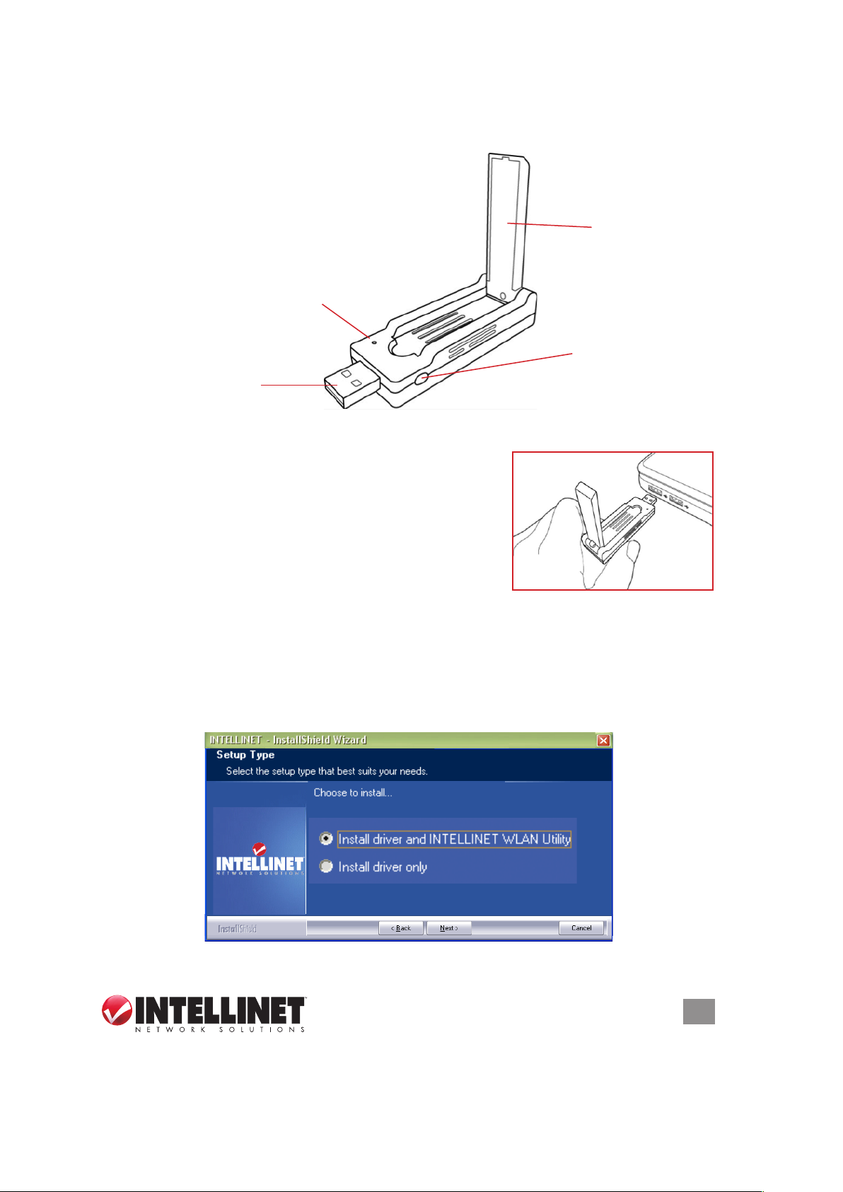
1. Remove the adapter’s protective cap and ip the
external antenna into an upright position.
2. With your computer on, gently insert the adapter
into a USB 2.0 port.
3. The Welcome to the Found New Hardware Wizard
screen will display automatically. Click “Cancel” to
continue.
4. Insert the included setup CD and run the “Setup.exe” program. Read the
license agreement that displays; select “I accept the terms of the license
agreement” and click “Next” to continue.
5. On the Setup Type screen, select “Install driver and INTELLINET WLAN
Utility.” Select “Install driver only” if you prefer to use the Windows integrated
WLAN function. Click “Next.”
WPS button —
Press to activate
the WPD Pairing
mode
IN STA LL ATI ON
5
Page 6
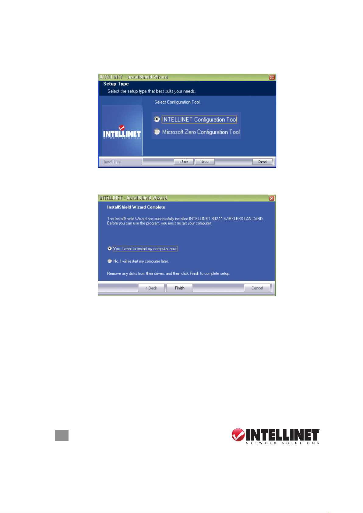
6. In Windows XP, a “Microsoft Zero Conguration Tool” option displays. It’s
recommended that the alternative “INTELLINET Conguration Tool” option be
selected, as it features more functions. Click “Next.”
7. Once the software installation is complete, select “Yes, I want to restart my
computer.”
6
IN STA LL ATI ON
Page 7
CONFIGURATION
The conguration utility — which displays automatically once the adapter is
connected — is a useful utility that helps you congure the adapter and monitor
link status and statistics during the communication process. This adapter will autoconnect to the wireless device
that has the best signal strength
and no wireless security setting.
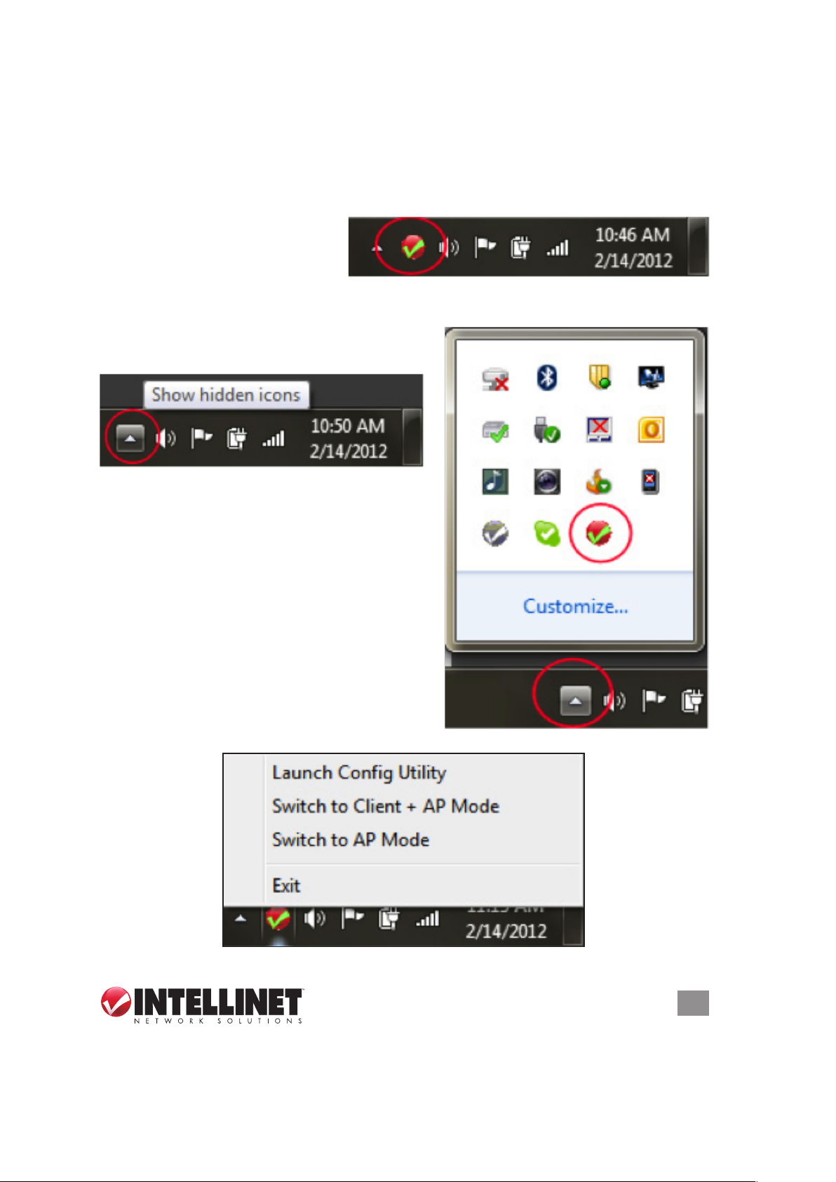
The conguration utility icon appears in the Windows systems tray while the
adapter is running. You can open it by double-clicking on the icon.
NOTE: On some systems, the icon may only
be visible when you view hidden icons:
Right-clicking the icon reveals several
choices (which may vary depending on the
operating system used):
CONFIGURATION
7
Page 8
Launch Cong Utility
This starts the conguration utility. It performs the same function as double-
clicking the icon.
Switch to Client + AP Mode
In this mode, the Intellinet Wireless 450N Dual-Band USB Adapter acts as both a
wireless network adapter for your computer and an access point for other wireless
devices to connect to the network. In most cases, this function is not needed and
should not be activated.
Switch to AP Mode
In this mode, the wireless USB adapter acts as an access point for other wireless
devices to connect to the network, but it does not function as a regular wireless
network adapter. In most cases, this function is not needed and should not be
activated.
Windows Zero Conguration Tool (not shown)
In Windows XP, there is a Windows Zero Conguration Tool (WZC) option for
setting up wireless clients. When it’s selected, you will not use the Intellinet WLAN
conguration utility to connect to any wireless network. Instead, you will use the
Windows integrated so-called “Zero Cong” function. If you are experienced in the
use of the Windows Zero conguration function, you can use it instead of the
Intellinet WLAN conguration utility. Unless you plan on using the AP mode
function of the WLAN adapter, there are no disadvantages to using Windows Zero
conguration over the Intellinet WLAN conguration utility. (This user manual only
includes instructions for the Intellinet WLAN conguration utility, however.)
Intellinet WLAN Utility Main Screen
8
CONFIGURATION
Page 9
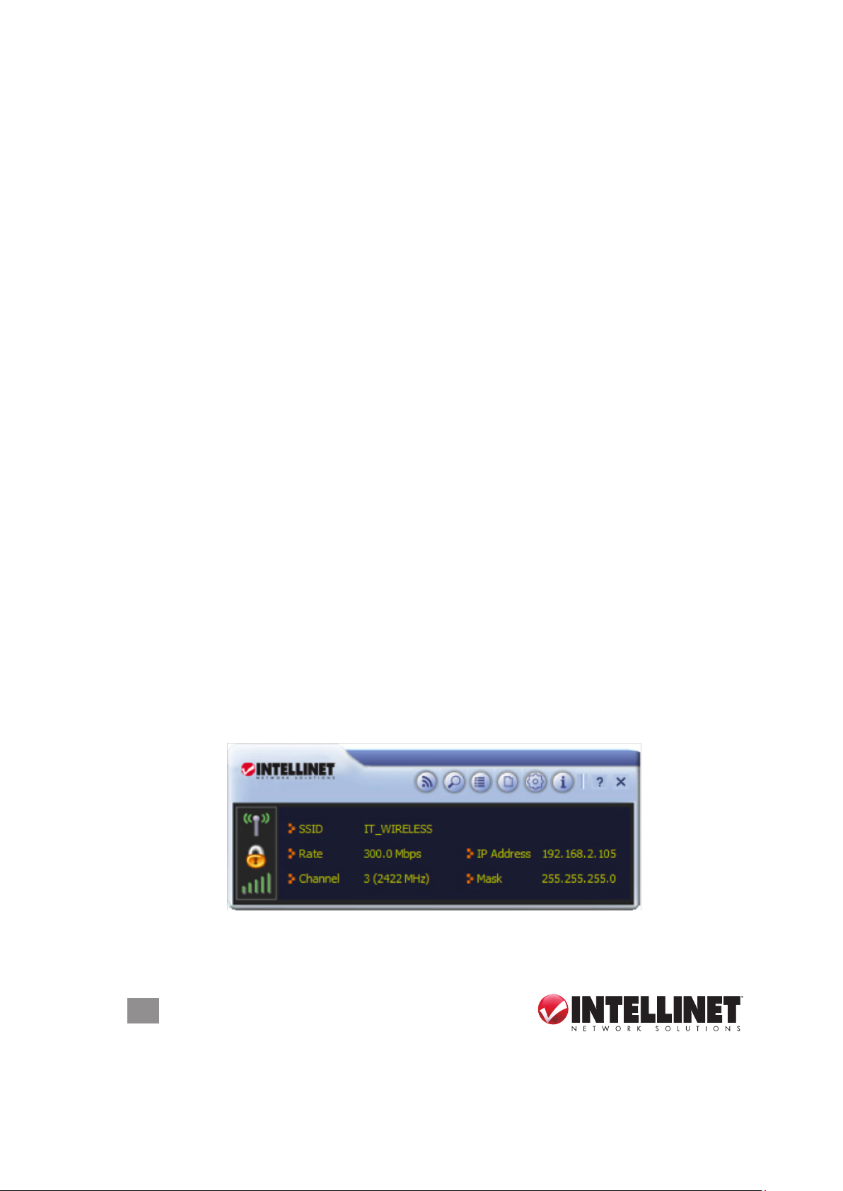
After you launch the utility, you’ll be
presented with the main screen. The
screen provides you with information
about your current wireless connection, such as the name (SSID) of the network
the computer is connected to, the current data rate and the computer’s IP address.
It also provides links to the various functions that the utility provides.
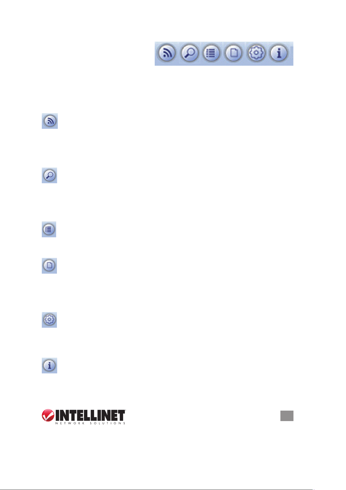
Wi-Fi Direct
Wi-Fi Direct is a standard that allows Wi-Fi devices to connect to each other
with no need for a wireless access point. It is similar to the older Ad-Hoc
mode, but it is easier to set up and provides more functionality. Refer to the
detailed Wi-Fi Direct section (Page 20) for details on how to use it.
Available Networks
Click this button to have the Intellinet wireless adapter scan for and display
a list of all wireless networks in range. Double-click an entry on that list to
establish a connection to that network. Read more in the Connecting to a Wireless
Network section (Page 10).
Link Information
Click for detailed information about the current wireless connection, which
some might even nd interesting.
Prole List
Whenever you establish a connection to a Wireless network, you can add
the connection to your prole list, enabling you to later quickly join the
network without having to provide the security credentials again. Read more on
this in the Prole List section (Page 11).
Advanced
Access to advanced settings is possible via this function. It is not needed
under normal circumstances to make any changes here. See the Advanced
Settings section (Page 18) for details.
About
This screen displays information about the software version of the WLAN
utility.
CONFIGURATION
9
Page 10
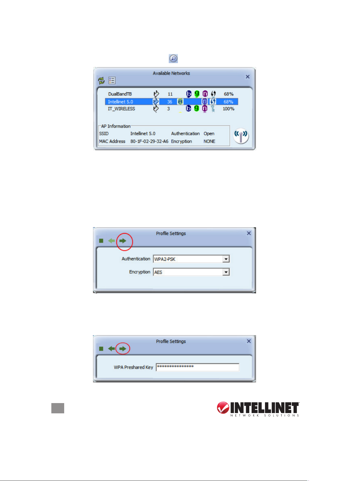
Connecting to a Wireless Network
Click on the Available Networks button
Locate your wireless network in the list, and double-click it. In case the wireless
network is protected by a security key, a screen will show up asking you to conrm
the wireless settings. The example below uses WPA2-PSK authentication and
AES encryption. If you do not know what this means, or if you do not know which
values your wireless network uses, don’t worry: The utility detects the settings
automatically for you, and under normal circumstances there is no need to make
any changes. Simply click on the circled right arrow — and don’t waste your time
wondering why this screen is even here.
for a list of available wireless networks.
The next step is to enter the actual password of the wireless network. This is often
referred to as the passphrase. It is important not to confuse this with the WPS
PIN code, which is explained later in this manual. You need to type in the correct
password and click on the right arrow to connect to the wireless network.
10
CONFIGURATION
Page 11

If the information you provided turns out to be correct, you’ll see a check mark
in front of the name of the network you’ve just connected to. The check mark
indicates a proper connection has been established.
If you entered a wrong password, the utility will not display an error message: It
will instead simply not show the check mark.
Another indication that something went wrong is when you click on the Link
Information button
and the screen displays “Status = Disconnected.”
Should that happen, double-click the network name and repeat the procedure —
until the utility indicates that you got it right!
Prole List
The properties of a connection — that is, the network name, the password, the
wireless channel and such — can be stored in a prole. If you connect to different
wireless networks on a regular basis, creating proles for these networks saves
you the trouble of entering the wireless password each and every time you want to
connect to the network.
Adding a Connection to a Prole
After you’ve successfully connected to a wireless network (see previous section),
CONFIGURATION
11
Page 12
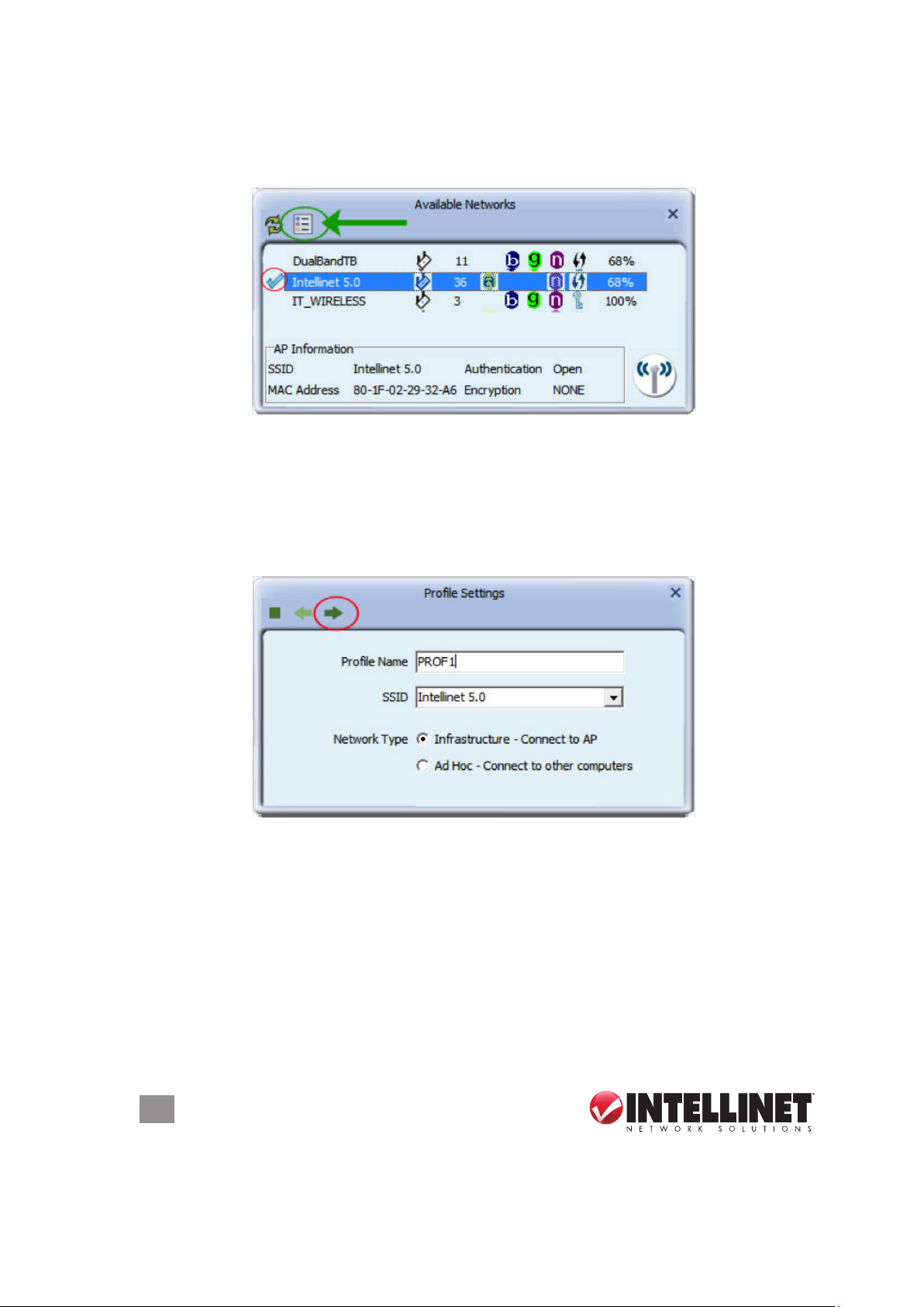
you can add that connection to a prole. To do that, open the Available Networks
screen, select the active connection indicated by the check mark (circled in red
below), then click on the icon (circled in green below).
The next screen allows you to provide a name for the prole (for example, “work
network”). The SSID (service set identier) will show the name of the network that
you’re connected to at the moment. The network type is set to the correct value by
default. (Infrastructure is by far the most common value.) Since the Intellinet WLAN
utility detects the correct settings by default, you should not make any changes to
the network type at this point.
On the next screen, you need to conrm the security settings and the optional
password (see previous section). After you’ve provided the correct information,
you’ll see the next screen, which asks you about the “Pre-logon Connection.”
When this feature is enabled, a wireless network connection will be established
before you log on to Windows so you can authenticate yourself against the
network server. If you don’t need this, you can leave this box unchecked. On
certain systems, the option is enabled by default and cannot be disabled (see the
screenshot). Click the right arrow to continue.
12
CONFIGURATION
Page 13

On the next screen you can dene the maximum translation output power (Tx Power)
of the wireless adapter. While you would normally leave the setting as “Auto” or
“100%” in situations where you do not want to have your signal travel so far (e.g.,
because you live in an apartment building), you can choose a lower value. After
all, being able to receive a wireless signal is the rst step in a successful attempt
to break into the network. In other words: Why would you want to broadcast your
wireless signal all over your neighborhood when your wireless access at home
works ne when it’s set at “50%” for output power?
The option “Use RTS Threshold” is disabled by default. Unless you experience
problems with your wireless connection, or if the signal strength is generally very
low, this doesn’t need to be enabled. If you experience poor wireless performance,
you can try using values between 1200 and 500, and below 500 in severe cases.
The option “Use Fragment Threshold” has a similar impact on poor wireless
connections. By default it is disabled and should remain so. The fragmentation
threshold is used to set the maximum size of packets that a client will send. The
smaller the maximum sizes the better the reliability of the wireless connection, but
the performance is likely to decrease at lower levels.
CONFIGURATION
13
Page 14

At this point, you’re done creating and connecting the prole. To activate it, click
on the icon (circled in red below).
Changing an Existing Prole
Click on the Prole List button
to open the prole list. Select the prole you
want to modify and click on the edit icon (circled). Editing the prole involves the
exact same steps and screens as creating a prole, which you have seen on the
previous pages.
Importing and Exporting a Prole
The Prole List screen allows you to save a prole to a hard drive or USB stick,
then reload it at a later time. This can be a useful tool for a network administrator
who needs to set up many computers for the same wireless network. After all,
entering the same password over and over on different systems can get old
quickly and it’s not exactly an efcient use of time.
When you click on one of the icons circled in red below, a screen will display that
allows you to either save a new prole or reload an existing one.
14
CONFIGURATION
Page 15

Creating a Prole with WPS
Besides adding a prole manually, you can connect to a wireless network and create
a prole based on WPS technology. Wi-Fi Protected Setup, also known as Wi-Fi
Simple Cong, is a computing standard that attempts to allow easy establishment
of a secure wireless home network. It lets you join a secure wireless network simply
by pushing a button or entering a PIN code) — without entering a complicated
password. WPS is still relatively new, and some wireless routers, especially older
models, don’t support it. If you’re not sure whether or not your router supports WPS,
there’s a simple way to nd out. The housing of the router must have a WPS button
(also called N-connect). If there’s no such button, you can stop reading this section
now because everything that follows would not be applicable to your network.
To begin, click on the Add WPS Prole button.
You’ll then see the screen below, presenting you with two choices:
• Push-Button Conguration (PBC)
• PIN / numeric code
CONFIGURATION
15
Page 16

To initiate a PBC connection, you need to rst press the WPS button on the router;
then, within two minutes, press the WPS button on the adapter. The two devices
will automatically connect to each other, and the wireless adapter will use the
correct network encryption key for your wireless network.
1. Press the WPS button
.
2. Press the WPS button
NOTE: The location of the WPS button on adapters varies. Yours may not even
have a physical WPS button.
If PBC involves physically pressing buttons, then why does the software have an
option for a push-button setup? The answer is simple: The same Intellinet WLAN
utility is included with the PCI WLAN Card and the tiny Wireless 150N Nano Adapter.
In the case of the card, it’s a matter of convenience. The software push-button
eliminates the need to get down on your knees to press the sometimes-hard-toreach PBC button on the card ... on the back of your computer underneath your desk.
In the case of the adapter, it’s a necessity. The adapter is so small that there’s just
no room to place a button on the product, making a virtual button mandatory.
As with the two-button procedure above, once you’ve pressed the PBC button on
the wireless router, you need to click on “Start PBC” within two minutes.
16
CONFIGURATION
Page 17

The utility will then scan for a wireless router currently accepting PBC requests.
If the scan is successful, the main Prole List screen displays and the network
name now has a preceding check mark.
Should you instead see the screen below, something went wrong. Either the WPS
button wasn’t pressed on the wireless router, or you didn’t press the Start PBC
button within two minutes after the button on the wireless router was pressed. If
you see the screen below, click on the Stop symbol (circled in red) to cancel the
scan attempt and try again.
CONFIGURATION
17
Page 18

Advanced
The Advanced screen lets you congure the wireless operational mode of your
adapter. Normally, there is no need to open this page and make any changes.
If your wireless adapter is capable of 2.4 and 5 GHz connections, as dual-band
adapters are, you can select the Wireless Mode setting here. By default, both
frequency bands are enabled. The option may be grayed out or not available,
depending on your wireless adapter.
The Country’s Region Code selection may also be grayed out, but, really, there is
no need to change this value. Nonetheless, it’s good to be able to see the values
that you cannot change.
The third option, B/G Protection, should be left at “Auto.” The B/G Protection mode
ensures that older wireless 802.11b and 802.11g devices will not degrade the
performance of the much faster wireless 802.3n network. So, if you have a mix of
older and newer wireless stations in the network, it’s recommended that you enable
the protection mechanism or leave it set to “Auto.” Only if you know for certain that
your network consists only of wireless N clients should you consider disabling this
option, as it can increase the performance of your connections ever so slightly.
18
CONFIGURATION
Page 19

The second Advanced screen is designed for network administrators and allows
for the installation of 802.1x WPA Enterprise certicates. Both user and issuer
certicates can be installed, though in most cases this won’t be required since the
certicate will likely have already been installed through the included Windows
components.
About
Click on the About button
installed and other things. If you ever need to contact Technical Support, it’s good
to have the information on this screen readily available for reference.
to view information about the utility itself, the driver
CONFIGURATION
19
Page 20

Wi-Fi Direct – Overview
Wi-Fi Direct is a standard that allows Wi-Fi devices to connect to each other without
a wireless access point. It’s become increasingly common for smartphones and
portable media players to include Wi-Fi as a standard feature, and it’s even become
common in feature phones. Currently, printers, cameras, scanners and many other
common devices can be found with Wi-Fi in addition to other connections, like USB.
The widespread adoption of Wi-Fi in new classes of smaller devices has made the
need for working ad hoc networking much more important. Even without a central
Wi-Fi hub or router, which we call access points, it would be useful for a laptop
computer to be able to wirelessly connect to a local printer. Although the ad hoc
mode was created to address this sort of need, the lack of additional information
for discovery makes it difcult to use in practice. Wi-Fi Direct, then, is a new and
improved way of device-to-device wireless connections and is the de facto
replacement of the former ad hoc mode.
1. Click on the Wi-Fi Direct button.
2. Double-click the circled icon and wait for the next screen to open up.
3. Enter a name for your Wi-Fi Direct device or use the computer name, which is
preselected.
20
CONFIGURATION
Page 21
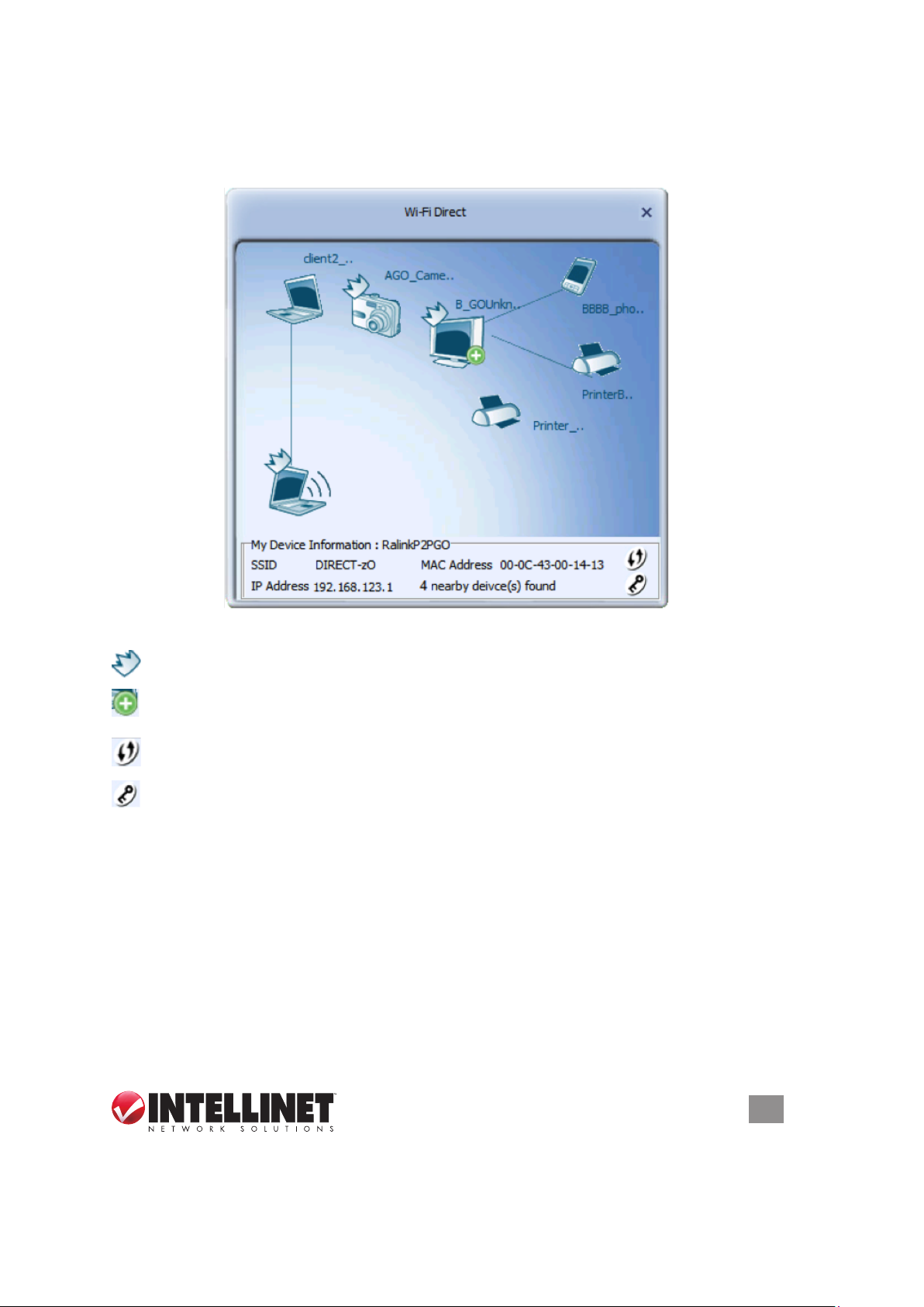
Once you’ve successfully activated Wi-Fi Direct service, the main screen will
display. Depending on whether or not Wi-Fi Direct–enabled devices are found, the
screen will look different:
Example 1: Wi-Fi–enabled devices are found in the network.
GO (Group Owner) indicates an access point or similar device.
This indicates that the device is the head of one or more client devices
(multiple clients belong to this GO).
This icon indicates that you can congure a secured connection with this
device via WPS.
This sets the WPA2AES encryption key.
CONFIGURATION
21
Page 22

Example 2: No Wi-Fi enabled devices are found in the network.
Right-click the laptop icon in the lower left corner to open the menu below.
Scan: Perform an active scan for available Wi-Fi Direct enabled devices.
Enable Quick Connection: Enables the Quick Connection mode.
Enable autonomous GO: Click to make your computer a group owner (GO),
symbolized by . Once this feature is enabled, you need to set the WPA
password. The default value is 12345678. It’s recommended that this be
changed to something more secure. Select the preferred channel for the new
Wi-Fi Direct group and click .
22
CONFIGURATION
Page 23

Back at the main screen, you should see , indicating that this computer is now
a group owner (GO).
Media Sharing: You can turn your computer into a media server for connected
Wi-Fi Direct clients. Enter a server name — e.g., mymediaserver — and specify
the folder on your hard drive you want to share. Click to start the service.
Click to re-start the service. Click to stop the service.
CONFIGURATION
23
Page 24

After you’ve enabled the media sharing function, other computers can see the
shared folder in the network environment. The example shows Ralink_Media_
Server, but it will be the name that you entered as the server name in the previous
step. Double-click the server icon to open Windows Media Player, allowing users
to play back the media les you shared.
Wi-Fi Direct – Creating and Accepting Connections
Accepting a Wi-Fi Direct Connection Request
If your computer’s Wi-Fi Direct function
is enabled and another client wants to
connect with your computer, a pop-up
message will alert you. Click the
message to accept the incoming
request.
Once the client is successfully connected, you can see the client on the Wi-Fi Direct
main screen (below). A line between the client and your computer indicates that a
connection has been established.
24
CONFIGURATION
Page 25

Establishing a Wi-Fi Direct Connection with Another Client
To establish connection with a P2P (peer to peer) device, double-click on its icon.
Doubleclick
CONFIGURATION
25
Page 26

You’ll be prompted to select its WPS connection type:
Push-Button Conguration: Select to use this method to establish a connection.
Display PIN: Select to use this method to establish a connection. With this method,
you’ll see an 8-digit number displayed here. Enter this number on the device
you want to connect to.
Enter PIN: Input the 8-digit PIN number displayed on the device you want to connect
to in the Pin Code eld to establish the connection.
Click to establish the connection.
AP Mode
This option allows you to turn your computer into a wireless access point (in this
case, a “soft” AP, made possible by the adapter software) that other wireless
devices can be connected to. Your computer could then share les, provide access
to the local network, and even share an existing Internet connection. When you
activate the AP mode as shown below, the wireless adapter will cease to function
as a regular wireless network adapter.
NOTE: If you’re thinking about activating this mode but the wireless adapter is the
only means for your computer to connect to a network, don’t do it. The AP mode
26
CONFIGURATION
Page 27

can only effectively be used if a second network connection, either wired or
wireless, is active.
Once you activate the AP mode, you’ll be asked to specify which network adapter
(other than the Intellinet wireless adapter) should be used for the AP mode. If the
goal is to share an existing Internet connection, then this adapter must provide an
Internet connection your computer. In the example below, the computer will use the
Intellinet Wireless 450N Dual-Band Adapter to provide wireless access point
functionality while the Intel 82577LM Gigabit adapter provides the Internet connection
to the computer. This is the connection you’ll be sharing wirelessly. If you’ve
understood everything so far, it should be clear that the screen may look different
during your setup since you likely have a different WAN adapter installed.
After you click on the right arrow, a brief message about enabling ICS (Internet
Connection Sharing) will display before the screen disappears.
The other thing that will disappear is the Intellinet wireless connection icon —
replaced by a new icon indicating that the AP mode is now
active. Right-click that icon and select “Open Utility” to start
the conguration utility for the AP mode.
CONFIGURATION
27
Page 28

APSetup
AccessControl
Connected
Advanced
Wirelesssignal
isactive
Wireless
connectionis
notencrypted
APmodeis
active
AP Setup
Now that your computer acts as a wireless access point, you can give the network
a proper name so that other computers can easily nd it. Enter a new name for
your wireless network in the SSID eld or leave the current one. If you don’t want
to openly broadcast the name of the network, activate the Hide SSID option.
The wireless mode is of importance on systems running a dual-band wireless
adapter as it denes which frequency band, 2.4 or 5 GHz, is to be used for the
access point. If you aren’t sure what to use, it’s always good advice to keep the
value at 2.4 GHz. Click the right arrow to move to the next screen.
You can adjust the wireless channel on the next screen. For optimal performance,
it’s best to use a channel that is furthest away from other wireless networks. For
28
CONFIGURATION
Page 29

example, if there is another wireless network running on channel 8, ideally you
want to use channel 2 or 1, as shown below. If you were to use a channel closer
to the existing wireless network, it would still work, but the performance would be
slightly diminished. If there are no other wireless networks around, or if you don’t
know which channel they operate on, it’s okay to leave the channel set at value “1.”
The option “Enable 40 MHz Bandwidth” should be selected for the best possible
performance. Click the right arrow to move to the next screen.
The next conguration aspect to consider is the security setup of the wireless
network. Unless you want to broadcast an unencrypted wireless signal that
everybody can connect to, it’s smart to secure the network with a password. First,
select the level of security from the Authentication drop-down menu:
• “Open” means that the wireless network will not be secured.
• “Shared” activates WEP encryption, but WEP encryption is very weak and should
only be used to connect legacy (older) devices that don’t support WPA or WPA2.
• “WPA-PSK” or (better) “WPA2-PSK” provides a good (and recommended) level
of protection; “WPA-PSK / WPA2-PSK” allows access to clients using either.
The Encryption option can be set to either “AES” or “TKIP,” AES being the preferred
option since it’s more efcient. TKIP is a fallback, in case a wireless adapter doesn’t
support AES. Click the right arrow to continue the conguration.
CONFIGURATION
29
Page 30

The next step is to enter the actual password, or passphrase, for the wireless
network. As for the Group Rekey Interval setting, the group key (or group transient
key) is a key shared among all wireless clients connected to the same AP, and
is used to secure multicast/broadcast trafc. The interval denes how often the
group transient key is changed. This is not the wireless password, however. This
mechanism works “behind the scenes” — completely hidden from you the user.
The default setting of “60” means that every 10 minutes (60 x 10 seconds = 600
seconds) the client receives a new group transient key. There can be a very brief
time period in which network access is interrupted as a result of this. A good value
to use is 360, which increases the interval to one hour. Higher values are also
acceptable and do not cause any problems.
The main screen now reloads, indicating that the wireless signal is protected.
Advanced
As with the Conguration Utility, click the Advanced icon
to view or change the
Advanced settings in AP mode. The enable/disable options, drop-down menus
and settings tables/lists are detailed below with their corresponding screens.
• No forwarding among wireless clients — When this option is activated, no
communication is possible between any wireless clients that are connected to
the “soft” AP. This, this option acts as a client isolation feature. When the option
30
CONFIGURATION
Page 31

is disabled, all wireless clients can freely communicate with each other. Choosing
which option is the right one depends on your network application.
• Beacon Interval (ms) — Access points broadcast trafc indication messages, or
beacons, in order to synchronize wireless networks. The beacon interval
species the duration in milliseconds between those beacon packets. The
default value of “100” typically does not need to be changed. If you prefer to
tweak the performance of your wireless network, you can lower the value (in
case your location be crowded by many different wireless networks creating a
lot of interference, perhaps) or you can raise the value (if you’re in a remote
locale with hardly any interference at all, for example). Then again, the effects
are minor to the point that only highly sensitive measuring tools can distinguish
the differences.
• Tx Power — This presents a menu of various output power ratings for the
adapter. If you want to limit the range of your wireless network to your ofce or
home in order to eliminate the possibility of an outside intruder breaking into your
network, you can lower the power setting to “75%,” “50%,” “25%” or “Low.”
• Idle Time — The default setting (“300”) doesn’t need to be changed.
Access Control List
The Access Control List offers yet another way to increase security. By combining
this feature with the four actions recommended above — WPA2 encryption, limiting
CONFIGURATION
31
Page 32

output power, enabling the “no forwarding between wireless clients” option and
hiding the SSID — you can make your network much more secure. Click the
Access Control List icon to display the feature’s conguration screen.
The MAC address is a unique hardware identication number assigned to
any network adapter during production. Whether the adapter is internal to a
notebook or iPad, or is a PCI network card in a desktop PC, the MAC address
is unique to that device. Therefore, it’s a means of identifying a connecting
computer, smartphone, tablet PC or laptop through the network adapter it uses.
• Access Policy — Select “Allow All” to create a white (spam-free) list of MAC
addresses so that only addresses you enter into the utility will be able to connect.
Select “Reject All” to create black list. In this case, access will be granted to any
MAC address that is not listed on the screen. Select “Disable” to deactivate the
function.
32
CONFIGURATION
Page 33

• MAC Address — Enter a 12-character address without no spaces, dashes or
colons; e.g., 001122334455. (Media access control, or MAC, addresses used
elsewhere can appear in 00:00:00:00:00 or 00-00-00-00-00 formats.) Based on
the MAC address of the wireless client, you can now decide whether to allow or
deny access.
• Add, Delete and Delete All — To add the currently displayed MAC address to
the list, click on the “Add” icon. To remove an address from the list, select it and
click on the “Delete” icon. Remove all MAC addresses on the list by clicking on
“Delete All.” NOTE: The utility will not ask you to conrm this; it deletes the
entries without question. So be careful not to accidentally overwrite a lot of MAC
addresses you may not have meant to delete.
Connected Devices
To display an overview of who is connected to the Soft AP, click on the Connected
Devices icon.
The example below shows one connected client.
To return the wireless adapter to the regular client mode, right-click the icon in the
systems tray and select “Switch to Client Mode.”
CONFIGURATION
33
Page 34

The utility will then deactivate ICS (Internet Connection Sharing) and return to the
original mode. The message below will be shown briey. This is completely normal
and is to be expected.
Client + AP Mode
In this mode the Intellinet Wireless 450N Dual-Band USB Adapter acts as both
the wireless network adapter for your computer and as an access point so other
wireless devices can connect to the network.
Click to open the access point conguration menu. Here, you can assign an
SSID and wireless encryption, and specify how many clients can use this connection.
Click to bring up the list of available wireless networks to which you can
connect with your wireless adapter.
34
CONFIGURATION
Page 35

The image above shows that
a) The wireless adapter is connected to the wireless network “IT_WIRELESS”; and
b) The wireless adapter broadcasts an access point signal as “SoftAP-66,” which
uses WPA2 encryption.
Any wireless client that connects to “SoftAP-66” will get Internet service via the
IT_WIRELESS network.
CONFIGURATION
35
Page 36

SPECIFICATIONS
NOTE: Specications are subject to change without notice.
Standards
• IEEE 802.11a (54 Mbps Wireless LAN)
• IEEE 802.11b (11 Mbps Wireless LAN)
• IEEE 802.11g (54 Mbps Wireless LAN)
• IEEE 802.11n (450 Mbps Wireless LAN)
• IEEE 802.11e (QoS Enhancement WMM)
General
• Interface: Hi-Speed USB 2.0
• Chipset: Ralink RT3573
• Frequency band:
- 2.400 – 2.483 GHz (Industrial Scientic Medical Band)
- 5.150 – 5.825 GHz (Industrial Scientic Medical Band)
• Modulation technologies:
- 802.11b: Direct Sequence Spread Spectrum (DSSS): DBPSK, DQPSK, CCK
- 802.11g: Orthogonal Frequency Division Multiplexing (OFDM): BPSK, QPSK,
16QAM, 64QAM
- 802.11n: Orthogonal Frequency Division Multiplexing (OFDM): BPSK, QPSK,
16QAM, 64QAM
• Security:
- 64/128-bit WEP data encryption
- WPA and WPA2
- Cisco CCX
• Transmit power 2.4 GHz:
- 11n: 14 dBm +/- 1.5 dBm
- 11g: 14 dBm +/- 1.5 dBm
- 11b: 16 dBm +/- 1.5 dBm
• Transmit power 5 GHz:
- 11n: 11 dBm +/- 1.5 dBm
- 11a: 11 dBm +/- 1.5 dBm
• Receive sensitivity 2.4 GHz:
- 11n 40 MHz: -66 dBm +/- 2 dBm
- 11n 20 MHz: -69 dBm +/- 2 dBm
- 11g: -71 dBm +/- 2 dBm
- 11b: -87 dBm +/- 2 dBm
• Receive sensitivity 5.0 GHz:
- 11n 40 MHz: -65 dBm +/- 2 dBm
36
SPECIFICATIONS
Page 37

- 11n 20 MHz: -69 dBm +/- 2 dBm
- 11a: -70 dBm +/- 2 dBm
• Antennas: 3T3R mode, 2 printed antennas, 1 external antenna
• Certication: FCC Class B, CE
LEDs
• Link/Activity
Environmental
• Dimensions: 18 (H) x 26.6 (W) x 87.1 (L) mm (0.7 x 1.0 x 3.4 in.)
• Weight: 0.16 kg (0.4 lbs.)
• Operating temperature: 0 – 40°C (32 – 104°F)
• Operating humidity: max. 90% RH, non-condensing
• Storage temperature: -20 – 60°C (-4 – 149°F)
System Requirements
• Windows XP/Vista and Windows 7
• Available Hi-Speed USB 2.0 type-A port
SPECIFICATIONS
37
Page 38

WASTE ELECTRICAL & ELECTRONIC EQUIPMENT
Disposal of Electric and Electronic Equipment
(applicable in the European Union and other European countries with separate collection systems)
This symbol on the product or its packaging indicates that this product shall not be
treated as household waste. Instead, it should be taken to an applicable collection
point for the recycling of electrical and electronic equipment. By ensuring
this product is disposed of correctly, you will help prevent potential negative
consequences to the environment and human health, which could otherwise be
caused by inappropriate waste handling of this product. If your equipment contains
easily removable batteries or accumulators, dispose of these separately according
to your local requirements. The recycling of materials will help to conserve natural
resources. For more detailed information about recycling of this product, contact
your local city ofce, your household waste
disposal service or the shop where you purchased this product. In countries
outside of the EU: If you wish to discard this product, contact your local authorities
and ask for the correct manner of disposal.
38
Page 39

COMPLIANCE STATEMENTS
FCC Class B
This equipment has been tested and found to comply with the limits for a Class B
digital device, pursuant to Part 15 of Federal Communications Commission (FCC)
Rules. These limits are designed to provide reasonable protection against harmful
interference in a residential installation. This equipment generates, uses and can
radiate radio frequency energy and, if not installed and used in accordance with
the instructions, may cause harmful interference to radio communications. However,
there is no guarantee that interference will not occur in a particular installation. If
this equipment does cause harmful interference to radio or television reception,
which can be determined by turning the equipment off and on, the user is encouraged
to try to correct the interference by one or more of the following measures:
• Reorient or relocate the receiving antenna.
• Increase the separation between the equipment and the receiver.
• Connect the equipment to an outlet on a circuit different from the receiver.
• Consult the dealer or an experienced radio/TV technician for help.
FCC Radiation Exposure Statement
This equipment complies with FCC radiation exposure set forth for an uncontrolled
environment. To avoid the possibility of exceeding FCC radio frequency exposure
limits, human proximity to the antenna shall not be less than 20 cm (8 inches)
during normal operation. The antenna(s) used for this transmitter must not be
co-located or operating in conjunction with any other antenna or transmitter. The
equipment version marketed in the U.S. is restricted to usage of channels 1-11.
CE / R&TTE
This device complies with the requirements of R&TTE Directive 1999/5/EC.
The ETSI version of this device is intended for home and ofce use in Austria,
Belgium, Denmark, Finland, France, Germany, Greece, Ireland, Italy, Luxembourg,
the Netherlands, Portugal, Spain, Sweden and the United Kingdom, and is also
authorized for use in EFTA member states Iceland, Liechtenstein, Norway and
Switzerland.
39
Page 40

INTELLINET NETWORK SOLUTIONS™ offers a complete line
of active and passive networking products.
Ask your local computer dealer for more information or visit
www.intellinet-n etwork.com.
© IC INTRACOM. All rights reserved.
INTELLINET is a trademark of IC INTRACOM, registered in the U.S. and other countries.
 Loading...