

Page 1

FAST ETHERNET
OFFICE SWITCH
USER MANUAL
MO DEL 523929
ENGLISH
DEUTSCH
ESPAÑOL
FRANÇAIS
POLSKI
ITALIANO
INT-523929-UM-ML1-0712-02
Page 2

Fast Ethernet Oce Switch • User Manual English
Thank you for purchasing the INTELLINET NETWORK SOLUTIONS™ Fast
Ethernet Oce Switch, Model 523929. For specications, go to
www.intellinet-network.com.
PLACEMENT
Prior to use, it is recommended that the switch be placed/positioned:
• on a level surface that can support the weight of the switch;
• with a minimum of 25 mm (approx. 1”) of clearance on the top and
sides for adequate ventilation;
• away from sources of electrical noise: radios, transmitters, broadband
ampliers, etc.;
• where it cannot be aected by excessive moisture.
The switch includes brackets and screws for optional rack mounting.
1. Disconnect any cables from the switch.
2. Position a bracket over the mounting holes on one side of the switch
and secure it in place with screws.
3. Repeat Step 2 on the other side of the switch.
4. Position the switch in the rack and screw the brackets to the rack.
5. Reconnect any cables.
CONNECTIONS
1. Use the included power cable to connect the receptacle on the back
of the switch to a power outlet, and conrm that the Power LED lights.
2. Make your connections to PCs, routers, hubs, other switches, etc.
• All ports on the switch support Auto-MDI/MDI-X functionality, so
crossover cables and uplink ports are not needed.
• When both the SFP mini-GBIC (ber) and RJ45 Gigabit (copper) ports
are connected, the system adopts the ber interface and disables the
corresponding copper port automatically.
• 10/100 auto sensing ports automatically detect optimal network
speeds; supports any combination of 10 Mbps or 100 Mbps network
devices with full/half-duplex operation.
2
ENGLISH
Page 3
Power
Link/Act
3
1
2
7
8
13
14
19
20
5
4
9
11
10
15
17
16
21
23
22
1X 2X 3X 4X
6
12
18
24
13X 14X 15X 16X
s
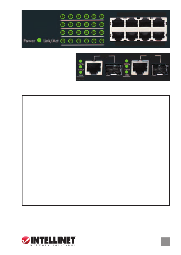
LED
The front panel LEDs
present network status and
connectivity information,
as detailed in the chart
The SFP mini-GBIC (ber) ports share LEDs with the RJ45 Gigabit
NOTE:
below.
(copper) ports: 25X/26X.
25X
1000M
100M
10M
Link/Act Link/Act
1000M
100M
10M
26X
LED Status Operation
Power On Unit is receiving power.
O Unit is not receiving power.
Link/Act On A valid network connection has been established.
Blinking Port is transmitting/receiving data.
O No link established.
1000M On A valid network connection has been established in the
1000M mode.
Blinking Port is transmitting/receiving data.
O No link established.
100M On A valid network connection has been established in the
100M mode.
Blinking Port is transmitting/receiving data.
O No link established.
10M On A valid network connection has been established in the
10M mode.
Blinking Port is transmitting/receiving data.
O No link established.
ENGLISH
3
Page 4

Fast Ethernet Oce Switch • Handbuch Deutsch
Vielen Dank für den Kauf des INTELLINET NETWORK SOLUTIONS™ Fast
Ethernet Oce Switch, Modell 523929. Die Spezikationen nden Sie
auf www.intellinet-network.com.
NUTZUNGSUMGEBUNG
Er wird empfohlen, den Switch vor der Nutzung folgendermaßen
aufzustellen:
• auf ebenem Untergrund, der das Gewicht des Switches (und evtl.
anderer Gegenstände) trägt;
• mit mindestens 25 mm Abstand zu allen Seiten für angemessenen
Luftdurchsatz;
•
fern von anderen Übertragungsgeräten wie Radios, Breitbandverstärker, etc.;
• nicht in feuchten Umgebungen.
Diesem Switch liegen Haltewinkel und Schrauben für optionale
Rackmontage bei.
1. Trennen Sie alle Kabel von dem Switch.
2. Platzieren Sie einen Haltewinkel über den Montagelöchern auf einer
Seite des Switches und xieren Sie ihn mit Schrauben.
3. Wiederholen Sie Schritt 2 auf der anderen Seite des Switches.
4. Platzieren Sie den Switch in dem Rack und schrauben Sie die Haltewinkel
fest.
5. Schließen Sie alle Kabel wieder an.
ANSCHLÜSSE
1. Verwenden Sie das beiliegende Stromkabel, um die Strombuchse auf
der Rückseite des Switches mit einer Steckdose zu verbinden und
prüfen Sie, dass die Power-LED leuchtet.
2. Schließen Sie PCs, Router, Hubs, andere Switche etc an.
• Alle Ports dieses Switches unterstützen Auto-MDI/MDI-X. Crossover Kabel und Uplink-Ports werden daher nicht benötigt.
• Wenn sowohl die SFP mini-GBIC (Glasfaser) als auch die RJ45-Gigabit (Kupfer) Ports verbunden sind, übernimmt das System die Glasfaser schnittstelle und deaktiviert automatisch den entsprechenden
Kupfer-Port.
• 10/100 Mbps automatische Geschwindigkeitserkennung; unterstützt
alle Kombinationen von 10 Mbps oder 100 Mbps Netzwerkgeräten;
Voll-/ und Halb-Duplex Modus.
4
DEUTSCH
Page 5
Power
Link/Act
3
1
2
7
8
13
14
19
20
5
4
9
11
10
15
17
16
21
23
22
1X 2X 3X 4X
6
12
18
24
13X 14X 15X 16X
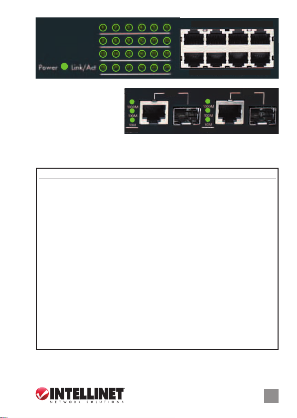
LEDs
Die LEDs auf der
Vorderseite zeigen den
Netzwerkstatus und
Informationen über die
25X
1000M
100M
10M
Link/Act Link/Act
1000M
100M
10M
26X
Verbindung an. Details entnehmen Sie bitte unten stehender Tabelle.
HINWEIS: Die SFP mini-GBIC (Glasfaser) Ports teilen sich folgende LEDs
RJ45-Gigabit- (Kupfer) Ports: 25X/26X.
LED Status Bedeutung
Power An Einheit nimmt Strom auf.
Aus Einheit nimmt keinen Strom auf.
Link/Act An Eine Netzwerkverbindung wurde hergestellt.
Blinkend Port überträgt/empfängt Daten.
Aus Keine Verbindung hergestellt.
1000M An Eine Netzwerkverbindung im 1000M-Modus wurde
hergestellt.
Blinkend Port überträgt/empfängt Daten.
Aus Keine Verbindung hergestellt.
100M An Eine Netzwerkverbindung im 100M-Modus wurde
hergestellt.
Blinkend Port überträgt/empfängt Daten.
Aus Keine Verbindung hergestellt.
10M An Eine Netzwerkverbindung im 10M-Modus wurde
hergestellt.
Blinkend Port überträgt/empfängt Daten.
Aus Keine Verbindung hergestellt.
DEUTSCH
5
Page 6

Switch de Ocina Fast Ethernet • Manual del Usuario Español
Gracias por comprar el Switch de Ocina Fast Ethernet de INTELLINET
NETWORKS™, Modelo 523929. Para más especicaciones, visite
www.intellinet-network.com.
MODO DE COLOCACIÓN
Antes de utilizarlo, se recomienda que el switch sea colocado/jado:
• Sobre una supercie plana que pueda soportar el peso del switch (y
cualquier otro artículo que deba ser considerado);
• Con un mínimo de 25 mm (1” aprox.) de espacio libre en la parte superior
y a los lados para una ventilación adecuada;
• Apartado de fuentes de ruido eléctrico: radios, transmisores,
amplicadores, etc.;
• Donde no sea afectado por la humedad excesiva.
El switch incluye los soportes y tornillos para su montaje en Rack (opcional).
1. Desconecte cualquier cable del switch.
2. Coloque el soporte sobre los oricios de montaje ubicados a un lado
del switch y sujételo con los tornillos.
3. Repita el paso 2 en el lado contrario del switch.
4. Coloque el switch en el rack y atornille los soportes al rack.
5. Conecte nuevamente todos los cables.
CONEXIONES
1. Utilice el cable de corriente incluido para conectar la parte trasera del
switch con una toma de corriente, y conrme que el LED de encendido
se ilumina.
2. Realice las conexiones a la PC, ruteadores, hubs, otros switches, etc.
• Todos los puertos soportan las funciones MDI/MDI-X de forma
automática, por lo que los cables cruzados y puertos uplink no son
necesarios.
• Cuando ambos puertos SFP mini-GBIC (bra óptica) y RJ45 Gigabit
(cobre) esten conectados, el sistema adoptara la interfaz de bra
correspondiente y desactivara el puerto de cobre de manera
automática.
• Puertos auto sensitivos 10/100 que detectan automáticamente la
velocidad óptima de red; soporta cualquier combinación de
dispositivos de red de 10 ó 100 Mbps con operación full/half dúplex.
6
ESPAÑOL
Page 7

Power
Link/Act
3
1
2
7
8
13
14
19
20
5
4
9
11
10
15
17
16
21
23
22
1X 2X 3X 4X
6
12
18
24
13X 14X 15X 16X
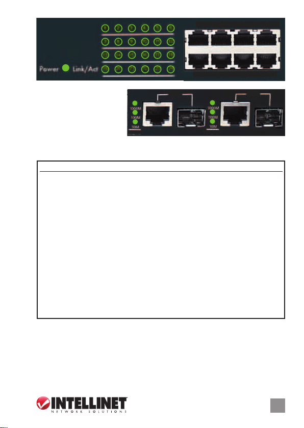
LEDs
Los LEDs en la parte
frontal representan el
estado de la red y la
información de conexión,
25X
1000M
100M
10M
Link/Act Link/Act
1000M
100M
10M
26X
como se detalla en la tabla siguiente. NOTA: Los puertos SFP mini-GBIC
(bra) comparten los LEDs con los puertos RJ45 Gigabit (cobre): 25X/26X.
LED Estado Operación
Power Encendido El dispositivo recibe energía.
Apagado El dispositivo no está recibiendo energía.
Link/Act Encendido Se establece una conexión de red valida.
Parpadeo El puerto está transmitiendo/recibiendo datos.
Apagado El puerto no está conectado.
1000M Encendido Se establece una conexión de red valida en modo de
1000Mbps.
Parpadeo El puerto está transmitiendo/recibiendo datos.
Apagado El puerto no está conectado.
100M Encendido Se establece una conexión de red valida en modo de
100Mbps.
Parpadeo El puerto está transmitiendo/recibiendo datos.
Apagado El puerto no está conectado.
10M Encendido Se establece una conexión de red valida en modo de
10Mbps.
Parpadeo El puerto está transmitiendo/recibiendo datos.
Apagado El puerto no está conectado.
ESPAÑOL
7
Page 8

Commutateur de bureau Fast Ethernet • Manuel de l’utilisateur Français
Merci d’avoir acheté le Commutateur de bureau Fast Ethernet INTELLINET
NETWORK SOLUTIONS™, modèle 523929. Vous trouvez les spécications
sur www.intellinet-network.com.
PLACEMENT
Avant d’utiliser le commutateur, il est recommandé de le placer:
• sur une surface plane qui peut supporter son poids (et celui d’autres
objets);
• ac. un écartement minimal de 25 mm d’autres objets pour une ventilation
susante;
• loin des appareils électriques qui peuvent être source d‘interférence
(des radios etc.);
• loin des environnements humides.
Le commutateur inclut des équerres et vis pour un montage en rack
optionnelle.
1. Déconnectez tous les cordons du commutateur.
2. Positionnez une équerre sur les trous de montage à un côté du
commutateur et sécurisez-la avec des vis.
3. Répétez l’étape 2 à l’autre côté du commutateur.
4. Positionnez le commutateur en rack et vissez les équerres au rack.
5. Reconnectez tous les cordons.
CONNEXIONS
1. Utilisez le cordon d’alimentation inclus pour connecter l’entrée
d’alimentation au panneau arrière du commutateur à une prise de
courant et conrmez que la DEL s’allume.
2. Connectez vos ordinateurs, routeurs, hubs, autres commutateurs, etc.
• Tous les ports sur ce commutareur supportent Auto-MDI/MDI-X ,
donc il ne faut pas de câbles croisés et des ports uplink.
• Quand les ports SFP mini-GBIC (bre) et RJ45 Gigabit (cuivre) sont
connectés, le système adopte l’interface bre et désactive le port
cuivre correspondant automatiquement.
• Ports 10/100 automatiques détecte la vitesse optimale du réseau;
prend en charge toutes combinaisons de connexions en 10 ou 100
Mbps; duplex intégral et semi-duplex.
8
FRANÇAIS
Page 9
Power
Link/Act
3
1
2
7
8
13
14
19
20
5
4
9
11
10
15
17
16
21
23
22
1X 2X 3X 4X
6
12
18
24
13X 14X 15X 16X
DELs
Les DELs sur le panneau
avant achent l’état du
réseau et des
sur la connectivité comme
informations
25X
1000M
100M
10M
Link/Act Link/Act
1000M
100M
10M
26X
détaillé ci-dessous. REMARQUE: Les SFP mini-GBIC (bre) partagent les
DELs avec les ports RJ45 Gigabit (cuivre): 25X/26X.
DEL État Description
Power Allumé L’unité est sous tension.
Éteint L’unité n’est pas sous tension
Link/Act Allumé Une connexion réseau est établie.
Clignotant Port transmet/reçoit des données.
Éteint Lien n’est pas établi.
1000M Allumé Une connexion réseau est établie en mode 1000M.
Clignotant Port transmet/reçoit des données.
Éteint No link established.
100M Allumé Une connexion réseau est établie en mode 100M.
Clignotant Port transmet/reçoit des données.
Éteint Lien n’est pas établi.
10M Allumé Une connexion réseau est établie en mode 100M.
Clignotant Port transmet/reçoit des données.
Éteint Lien n’est pas établi.
FRANÇAIS
9
Page 10

Przełącznik Fast Ethernet Oce • Instrukcja użytkownika Polski
Dziękujemy za zakup Przełącznika Fast Ethernet Oce INTELLINET
NETWORK SOLUTIONS™, model 523929. Pełną specykację produktu
znajdziecie Państwo na stronie www.intellinet-network.com.
UMIEJSCOWIENIE
Zaleca się, aby urządzenie w trakcie użytkowania było umiejscowione:
• na płaskiej powierzchni, w miejscu odpowiednim do wagi urządzenia;
• dla zapewnienia dobrej wentylacji w odległości co najmniej 25 mm
obudowy urządzenia od podłoża, na którym się znajduje;
• z dala od źródeł zakłóceń elektrycznych: radia, nadajniki szerokopasmowe,
itp.;
• z dala od nadmiernej wilgoci.
W zestawie znajdują się uchwyty oraz śrubki do opcjonalnego mocowania
rackowego.
1. Odłącz wszystkie kable od przełącznika.
2. Umieść uchwyt na dziurach na bocznej części przełącznika i przykręć
go śrubami.
3. Powtórz czynność z punktu nr 2 dla drugiego uchwytu.
4. Umieść przełącznik w racku i przykręć go śrubami.
5. Podłącz kable.
PODŁĄCZENIE
1. Użyj dołączonego kabla, aby podłączyć zasilanie do gniazda na tylnym
panelu przełącznika, sprawdź, czy zapaliła się dioda zasilania.
2. Wykonaj połączenia do komputerów, routerów, hubów, innych
przełączników, itp.
• Wszystkie porty przełącznika obsługują funkcję Auto-MDI/MDI-X, tak
więc nie ma potrzeby stosowania kabli krosowych i portów uplink.
• Kiedy podłączony jest zarówno port SFP mini-GBIC (światłowód) i
porty RJ45 Gigabit (miedź), system wykorzystuje interfejs światłowodowy
i wyłącza odpowiedni port miedziany automatycznie.
• Automatyczne wykrywanie optymalnej prędkości sieci 10/100 na
każdym porcie; obsługa dowolnej kombinacji urządzeń sieciowych
10 Mb/s oraz 100 Mb/s; tryby full/half duplex.
10
POLSKI
Page 11

Power
Link/Act
3
1
2
7
8
13
14
19
20
5
4
9
11
10
15
17
16
21
23
22
1X 2X 3X 4X
6
12
18
24
13X 14X 15X 16X
DIODY
Na przednim panelu diody
sygnalizacyjne LED
prezentują stan sieci i
informacje o połączeniach,
25X
1000M
100M
10M
Link/Act Link/Act
1000M
100M
10M
26X
tak jak opisano w poniższej tabeli. UWAGA: Porty SFP mini-GBIC
(światłowodowe) posiadają wspólne diody sygnalizacyjne LED z portami
RJ45 Gigabit (miedź) - 25X/26X.
Dioda Status Objaśnienie
Power On (wł.) Urządzenie jest zasilone.
O (wył.) Urządzenie nie jest zasilone.
Link/Act On (wł.) Połączenie z siecią zostało ustanowione.
Migająca Port transmituje/odbiera dane.
O (wył.) Port nie został prawidłowo podłączony.
1000M On (wł.) Połączenie z siecią zostało ustanowione w trybie 1000M.
Migająca Port transmituje/odbiera dane.
O (wył.) Port nie został prawidłowo podłączony.
100M On (wł.) Połączenie z siecią zostało ustanowione w trybie 100M.
Migająca Port transmituje/odbiera dane.
O (wył.) Port nie został prawidłowo podłączony.
10M On (wł.) Połączenie z siecią zostało ustanowione w trybie 10M.
Migająca Port transmituje/odbiera dane.
O (wył.) Port nie został prawidłowo podłączony.
POLSKI
11
Page 12

Switch Fast Ethernet Oce • Manuale d’istruzione Italiano
Grazie per aver scelto uno Switch Fast Ethernet Oce della linea INTELLINET
NETWORK SOLUTIONS™, Modello 523929. Per ulteriori speciche, visitare
il sito www.intellinet-network.com.
POSIZIONAMENTO
Prima di utilizzare il prodotto, si consiglia di fare attenzione a dove viene
collocato lo switch:
• su una supercie piana che può supportare il peso dello switch (o
qualsiasi altro oggetto che deve essere tenuto in considerazione);
• con un minimo di 25 mm (approssimativamente 1”) di spazio libero
verso l’alto e lateralmente per permettere un’adeguata ventilazione;
• lontano da sorgenti che possono provocare disturbi e interferenze
elettro magnetiche: radio, trasmettitori, amplicatori di banda, ecc.;
• dove non venga sottoposto ad eccessiva umidità.
Lo switch include stae e viti per il montaggio opzionale a rack.
1. Disconnettere qualsiasi cavo dallo switch.
2. Posizionare la staa sui fori di ssaggio su un lato dello switch e
assicurarla sul posto con le viti.
3. Ripetere il passo 2 per l’altro lato dello switch.
4. Posizionare lo switch sul rack ed avvitare le stae sul rack.
5. Ricollegare i cavi.
CONNESSIONI
1. Utilizzare il cavo di alimentazione incluso per collegare la presa sul
retro dello switch ad una presa di corrente e vericare che la luci del
LED di alimentazione sia accesa.
2. Eettuare le connessioni al PC, router, hub, o altri switch, etc.
• Tutte le porte sullo switch supportano la funzionalità Auto-MDI/
MDI-X, quindi cavi crossover e porte uplink non sono necessarie.
• Quando sia la porta SFP mini-GBIC (bra) che quella RJ45 Gigabit
(rame) sono collegate, il sistema sceglie l’interfaccia in bra e
disabilita automaticamente la corrispondente porta in rame.
• Le porte 10/100 auto sensing automaticamente individuano la
velocità di trasmissione dati ottimale; supporta periferiche con
qualsiasi combinazione di trasferimento dati a 10 Mbps o 100 Mbps;
modalità full/half duplex.
12
ITALIANO
Page 13

Power
Link/Act
3
1
2
7
8
13
14
19
20
5
4
9
11
10
15
17
16
21
23
22
1X 2X 3X 4X
6
12
18
24
13X 14X 15X 16X
LED
Il pannello frontale con i
LED presenta lo stato della
rete e le informazioni sulla
connettività, come visibile
25X
1000M
100M
10M
Link/Act Link/Act
1000M
100M
10M
26X
in dettaglio nel graco sotto riportato. NOTA: le porte SFP mini-GBIC (bra)
condividono i LED con le porte RJ45 Gigabit (rame): 25X/26X.
LED Stato Operazione
Power Accesso L’unità sta ricevendo corrente.
Spento L’unità sta ricevendo corrente.
Link/Act Accesso Una connessione di rete valida è stata stabilità.
Lampeggiante La porta sta trasmettendo/ricevendo i dati.
Spento Nessuna connessione stabilita.
1000M Accesso Una connessione di rete valida è stata stabilità in
modalità 1000M.
Lampeggiante La porta sta trasmettendo/ricevendo i dati.
Spento Nessuna connessione stabilita.
100M Accesso Una connessione di rete valida è stata stabilità in
modalità 100M.
Lampeggiante La porta sta trasmettendo/ricevendo i dati.
Spento Nessuna connessione stabilita.
10M Accesso Una connessione di rete valida è stata stabilità in
modalità 10M.
Lampeggiante La porta sta trasmettendo/ricevendo i dati.
Spento Nessuna connessione stabilita.
ITALIANO
13
Page 14

WASTE ELECTRICAL & ELECTRONIC EQUIPMENT
(applicable in the European Union and other European countries with separate collection systems)
ENGLISH
This symbol on the product or its packaging indicates that this product shall not be treated as household waste.
detailed information about recycling of this produc t, contac t your local city oce, your household waste
disposal service or the shop where you purchased this product. In countries outside of the EU: If you wish
to discard this product, contact your local authorities and ask for the correct manner of disposal.
DEUTSCH
Dieses auf dem Produkt oder der Verpackung angebrachte Symbol zeigt an, dass dieses Produkt nicht mit
dem Hausmüll entsorgt werden darf. In Übereinstimmung mit der Richtlinie 2002/96/EG des Europäischen
Parlaments und des Rates über Elektro- und Elektronik-Altgeräte ( WEEE) darf dieses Elektrogerät nicht
im normalen Hausmüll oder dem Gelben Sack entsorgt werden. Wenn Sie dieses Produkt entsorgen
möchten, bringen Sie es bitte zur Verkaufsstelle zurück oder zum Recycling-Sammelpunkt Ihrer Gemeinde.
ESPAÑOL
Este símbolo en el producto o su embalaje indica que el producto no debe tratarse como residuo doméstico.
De conformidad con la Directiva 2002/96/CE de la UE sobre residuos de aparatos eléctricos y electrónicos
(RAEE), este producto eléctrico no puede desecharse con el resto de residuos no clasicados. Deshágase
de este producto devolviéndolo a su punto de venta o a un punto de recolección municipal para su
reciclaje.
FRANÇAIS
Ce symbole sur Ie produit ou son emballage signie que ce produit ne doit pas être traité comme un
déchet ménager. Conformément à la Directive 2002/96/EC sur les déchets d’équipements électriques
et électroniques (DEEE), ce produit électrique ne doit en aucun cas être mis au rebut sous forme de
déchet municipal non trié. Veuillez vous débarrasser de ce produit en Ie renvoyant à son point
de vente ou au point de ramassage local dans votre municipalité, à des ns de recyclage.
ITALIANO
Questo simbolo sui prodotto o sulla relativa confezione indica che il prodotto non va trattato come un riuto
domestico. In ottemperanza alla Direttiva UE 2002/96/EC sui riuti di apparecchiature elettriche ed
elettroniche (RAEE), questa prodotto elettrico non deve essere smaltito come riuto municipale misto. Si
prega di smaltire il prodotto riportandolo al punto vendita o al punto di raccolta municipale locale per un
opportuno riciclaggio.
POLSKI
Jeśli na produkcie lub jego opakowaniu umieszczono ten symbol, wówczas w czasie utylizacji nie wolno
wyrzucać tego produktu wraz z odpadami komunalnymi. Zgodnie z Dyrektywą Nr 2002/96/WE w sprawie
zużytego sprzętu elektrycznego i elektronicznego (WEEE), niniejszego produktu elektrycznego nie wolno
usuwać jako nie posortowanego odpadu komunalnego. Prosimy o usuniecie niniejszego produktu
poprzez jego zwrot do punktu zakupu lub oddanie do miejscowego komunalnego punktu zbiórki
odpadów przeznaczonych do recyklingu.
Disposal of Electric and Electronic Equipment
Instead, it should be taken to an applicable collection point for the recycling of electrical and
electronic equipment. By ensuring this product is disposed of correctly, you will help prevent
potential negative consequences to the environment and human health, which could otherwise
be caused by inappropriate waste handling of this product. If your equipment contains easily
removable batteries or accumulators, dispose of these separately according to your local
requirements. The recycling of materials will help to conserve natural resources. For more
14
Page 15

WARRANTY INFORMATION
ENGLISH:
For warranty information, go to www.intellinet-network.com/warrant y.
DEUTSCH:
Garantieinformationen nden Sie unter www.intellinet-net work.com/warranty.
ESPAÑOL:
Si desea obtener información sobre la garantía, visite www.intellinet-network.com/warrant y.
FRANÇAIS:
Pour consulter les informations sur la garantie, visitez w ww.intellinet-net work.com/warranty.
POLSKI:
Informacje dotyczące gwarancji znajdują się na stronie www.intellinet-network.com/warranty.
ITALIANO:
Per informazioni sulla garanzia, accedere a www.intellinet-network.com/warranty.
EN MÉXICO: Póliza de Garantía INTELLINET — Datos del importador y responsable ante el consumidor
IC Intracom México, S.A. de C.V. • Av. Interceptor Poniente # 73, Col. Parque Industrial La Joya, Cuautitlán
Izcalli, Estado de México, C.P. 54730, México. • Tel. (55)1500-4500
La presente garantía cubre este producto por 3 años contra cualquier defecto de fabricación en sus
materiales y mano de obra, bajo las siguientes condiciones:
1. Todos los productos a que se reere esta garantía, ampara su cambio físico, sin ningún cargo para
el consumidor.
2. El comercializador no tiene talleres de servicio, debido a que los productos que se garantizan no
cuentan con reparaciones, ni refacciones, ya que su garantía es de cambio físico.
3. La garantía cubre exclusivamente aquellas partes, equipos o sub-ensambles que hayan sido instaladas
de fábrica y no incluye en ningún caso el equipo adicional o cualesquiera que hayan sido adicionados
al mismo por el usuario o distribuidor.
Para hacer efectiva esta garantía bastará con presentar el producto al distribuidor en el domicilio donde
fue adquirido o en el domicilio de IC Intracom México, S.A. de C.V., junto con los accesorios contenidos
en su empaque, acompañado de su póliza debidamente llenada y sellada por la casa vendedora
(indispensable el sello y fecha de compra) donde lo adquirió, o bien, la factura o ticket de compra
original donde se mencione claramente el modelo, número de serie (cuando aplique) y fecha de
adquisición. Esta garantía no es válida en los siguientes casos: Si el producto se hubiese utilizado
en condiciones distintas a las normales; si el producto no ha sido operado conforme a los instructivos
de uso; o si el producto ha sido alterado o tratado de ser reparado por el consumidor o terceras personas.
North & S outh Ameri ca
IC INTR ACOM AMERICAS
550 Commerce Blv d.
Oldsmar, FL 34 677
USA
All trademarks and trade names are the property of their respective owners.
Alle Marken und Markennamen sind Eigentum Ihrer jeweiligen Inhaber.
Todas las marcas y nombres comerciales son propiedad de sus respectivos dueños.
Toutes les marques et noms commerciaux sont la propriété de leurs propriétaires respectifs.
Tutti i marchi registrati e le dominazioni commerciali sono di proprietà dei loro rispettivi proprietari.
Wszystkie znaki towarowe i nazwy handlowe należą do ich właścicieli.
Asia & Afr ica
IC INTR ACOM ASIA
Far Eastern Techn ology Center
7-F No. 125, Secti on 2, Da Tong Rd.
Shijr, Taipei
Taiwan, ROC
Europe
IC INTR ACOM EUROPE
Löhbache r Str. 7
D-58553 Halver
Germany
15
Page 16

REGULATORY STATEMENTS
This equipment has been tested and found to comply with the limits for a Class B digital device,
pursuant to Part 15 of Federal Communications Commission (FCC) Rules. These limits are designed
to provide reasonable protection against harmful interference in a residential installation. This
equipment generates, uses and can radiate radio frequency energy, and if not installed and used
in accordance with the instructions may cause harmful interference to radio communications.
However, there is no guarantee that interference will not occur in a particular installation. If this
equipment does cause harmful interference to radio or television reception, which can be determined
by turning the equipment o and on, the user is encouraged to try to correct the interference by one or
more of the following measures:
• Reorient or relocate the receiving antenna.
• Increase the separation between the equipment and the receiver.
• Connect the equipment to an outlet on a circuit dierent from the receiver.
• Consult the dealer or an experienced radio/TV technician for help.
ENGLISH
English: This device complies with the requirements of R&TTE Directive 1999/5/EC.
The Declaration of Conformit y for this product is available at:
Deutsch: Dieses Gerät enspricht der Direktive R&TTE D irektive 1999/5/EC.
Die Konformitätserklärung für dieses Pro dukt finden Sie unter::
Español: Este dispositivo cumple con los requerimientos de la Directiva R&TTE 1999/5/EC.
La declaración de conformidad para este produ cto esta disponible en:
Français: Cet appareil satisfait aux exigences de la direc tive R&TTE 1999/5/CE.
La Déclaration de Conformité pour ce produit est disponible à l’adresset :
Polski: Urządzenie spe łnia wymagania dyrekty wy R&TTE 1999/5/EC.
Deklaracja zgodności dostępna jest na stronie internetowej pro ducenta:
Italiano: Questo dispositivo è conforme alla Direttiva 1999/5/EC R&TTE.
La dichiarazione di conformità per questo pro dotto è disponibile al:
FCC Class B
CE / R&TTE
intellinet-network.com
16
Page 17

Page 18

Page 19

Page 20

INT ELLINE T is a trad emark of IC INTR ACOM, reg ister ed in the U. S. and ot her coun tries.
© IC IN TRACOM . All righ ts rese rved.
 Loading...