

Page 1
8-Port
rackmount
PoE midsPan
usEr manual
Model 502931
ENGLISH
DEUTSCH
ES PAÑOL
FRANÇAIS
POLSKI
ITALIANO
INT-502931-UM-ML1-0710-01-0
Page 2

8-Port Rackmount PoE Midspan • User Manual English
Thank you for purchasing the INTELLINET NETWORK SOLUTIONS™ 8-Port
Rackmount PoE Midspan, Model 502931. For a full list of specications, refer
to the datasheet available at www.intellinet-network.com.
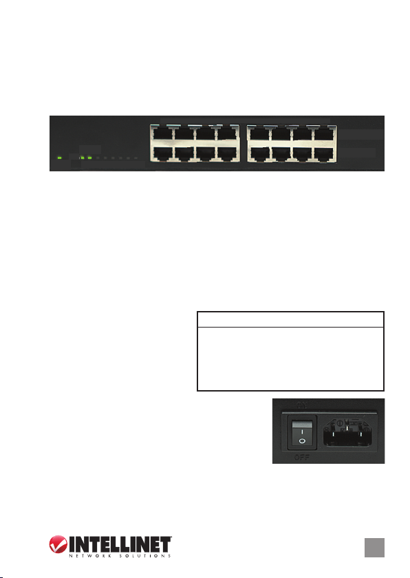
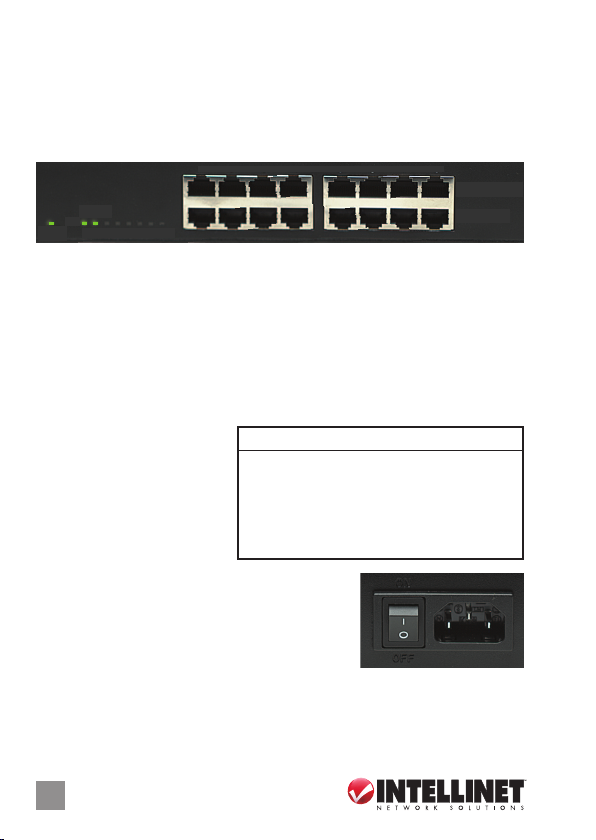
CONNECTIONS & INDICATORS
1 2 3 4 5 6 7 8
PD LINK
POWER
1 2 3 4 5 6 7 8
RJ45 10/100 Mbps ports
POWER + DATA (OUT)
DATA (IN)
Ports
The lower row of RJ45 ports — Data (In) — on the front panel delivers data
to the Midspan from existing network devices. The upper row of RJ45 ports
— Power + Data (Out) — delivers data while also powering added devices
(up to 15.4 Watts per port). Use standard Cat5 or better Ethernet cables for
connections to PoE-supported IP cameras, wireless access points, other
switches, etc. NOTE: Powered devices should also comply with IEEE 802.3af.
LEDs
If an LED doesn’t light to
indicate a link or activity,
check the corresponding
device for proper setup and
operation.
Power
On the rear panel, plug in the included power
LED Status Operation
POWER On Power on
O Check the AC connection; power on
PD Link On Port is linked and providing 48 V to a
(1-8) powered device
O No link is established
ON
cord and connect the switch to an AC outlet.
Toggle the Power switch to On and conrm that
the Power LED is lit.
RACK MOUNTING
OFF
Simply align the two brackets with the holes on each side panel and secure
them with the included screws. Use the remaining screws to mount the
device in a rack.
2
ENGLISH
Page 3
PoE Midspan • Handbuch Deutsch
Vielen Dank für den Kauf des INTELLINET NETWORK SOLUTIONS™ 8-Port
Rackmount PoE Midspan, Modell 502931. Ein Datenblatt mit der vollständigen
Liste aller Spezikationen nden Sie auf www.intellinet-network.com.
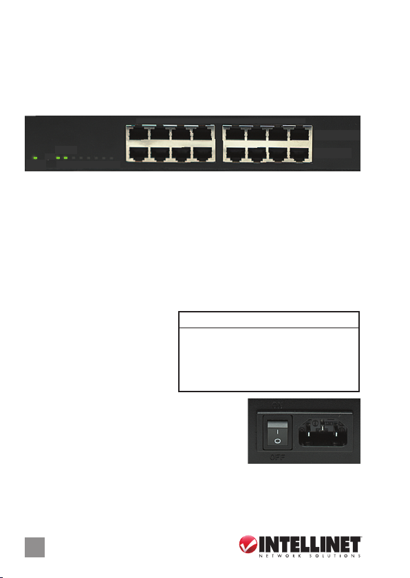
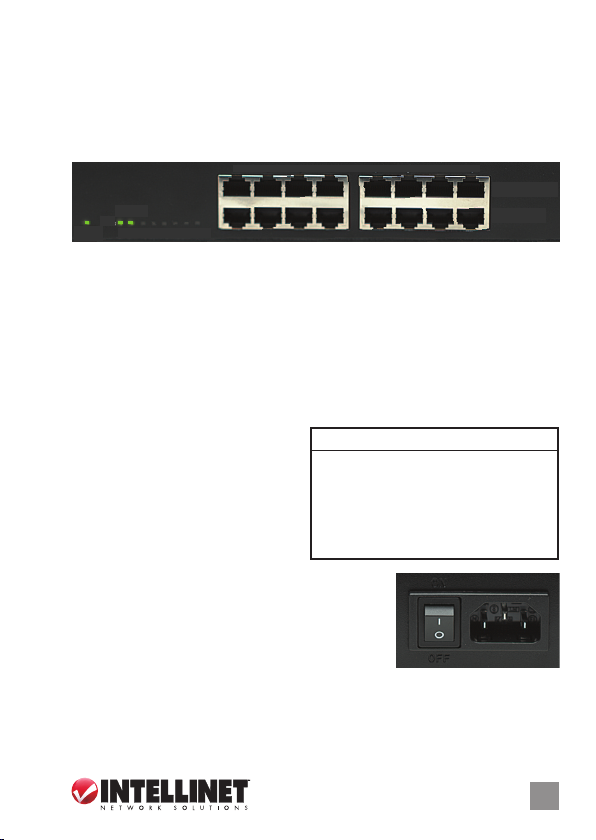
ANSCHLÜSSE & ANZEIGEN
1 2 3 4 5 6 7 8
PD LINK
POWER
1 2 3 4 5 6 7 8
RJ45 10/100 MBit/s-Ports
POWER + DATA (OUT)
DATA (IN)
Ports
Die untere Reihe der RJ45-Ports — Daten (Eingang) — an der Vorderseite liefert
Daten der vorhandenen Netzwerkgeräte an den Midspan. Die obere Reihe der
RJ45-Ports — Strom + Daten (Ausgang) — liefert Daten und versorgt angeschlossene
Geräte gleichzeitig mit Strom (bis zu 15,4 Watt pro Port). Verwenden Sie Standard
-Cat5- oder bessere Ethernet-Kabel für den Anschluss von IP-Kameras mit PoEUnterstützung, Wireless Access Points, anderen Switchen, etc. HINWEIS: Mit
Strom versorgte Geräte sollten außerdem mit IEEE 802.3af kompatibel sein.
LED-Anzeigen
Sollte eine LED-Anzeige von
Verbindung oder Aktivität nicht
leuchten, prüfen Sie das
entsprechende Gerät auf korrekte
Einrichtung und Betrieb.
Strom
Schließen Sie das beiliegende Stromkabel auf der
LED Status Bedeutung
POWER An G erät wird mit Strom versorgt
Aus Prüfen Sie die Steckdosenverbindung
PD Link An Port ist verbunden und liefert 48 V an
(1-8) angeschlossenes Gerät
Aus Keine Verbindung hergestellt
ON
Rückseite des Geräts und an einer Steckdose an.
Stellen Sie den Netzschalter auf Ein und prüfen Sie,
ob die “Power”-LED leuchtet.
RACKMONTAGE
OFF
Bringen Sie die beiden Befestigungswinkel auf Höhe der Löcher an den Seiten
an und xieren Sie sie mit den beiliegenden Schrauben. Verwenden Sie die
restlichen Schrauben, um das Gerät am Rack zu befestigen.
DEUTSCH
3
Page 4
Midspan PoE • Manual del usuario Español
Gracias por comprar el Midspan PoE para montaje en rack de 8 puertos
INTELLINET NETWORK SOLUTIONS™, Modelo 502931. Para obtener una lista
completa de especicaciones, consulte www.intellinet-network.com.
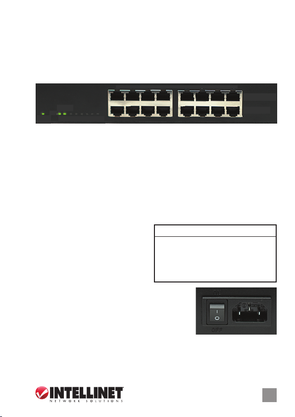
CONNECTIONS & INDICATORS
1 2 3 4 5 6 7 8
PD LINK
POWER
1 2 3 4 5 6 7 8
Puertos RJ45 10/100
POWER + DATA (OUT)
DATA (IN)
Puertos
La la inferior de los puertos RJ45 — Datos (IN) — en el panel frontal recibe
datos de lso dispositivos de red existentes. La la superior de los puertos
RJ45 — Power + Data (Out) — entrega datos y al mismo tiempo alimenta
dispositivos (hasta 15,4 Watts por puerto). Use cables estandard Cat5 o
superiores para conexiones PoE soportando cameras IP, Access Point
inalambricos, otros switches, etc. NOTA: Los dispositivos energizados deben
cumplir con IEEE 802.3af.
LEDs
Si un LED no enciende indica un
vinculo ó actividad, revise el
dispositivo correspondiente para
ajustar su conguracion y
operación.
Encendido
En el panel trasero, conecte el cable de corriente
LED Status Operación
POWER Encendido Encendido
Apgado Compruebe la conexion CA
PD Link Encendido Puerto esta vinculado y provee
(1-8) 48 V de energia por dispositivo
Apagado Sin comunicación
ON
incluido al switch y otro extremo a una toma de AC.
Mueva el switch de encendido para encender y
conrme que el LED de power está encendido.
MONTAJE EN RACK
OFF
Simplemente alinee los dos soportes con los agujeros en cada panel lateral
y jelos con los tornillos incluidos. Use los tornillos restantes para montar el
dispositivo en el rack.
4
ESPAÑOL
Page 5
8-Port Rackmount PoE Midspan
• Manuel de l’utilisateur Français
Merci d’avoir acheté le Commutateur rackable PoE Midspan 8 ports INTELLINET
NETWORK SOLUTIONS™, modèle 502931. Pour la che technique avec les
spécications complètes, visitez www.intellinet-network.com.
CONNEXIONS & INDICATEURS
1 2 3 4 5 6 7 8
PD LINK
POWER
1 2 3 4 5 6 7 8
Ports RJ45 10/100 Mbit/s
POWER + DATA (OUT)
DATA (IN)
Ports
La rangée inférieure des ports RJ45 — Données (Entrée) — sur le panneau avant
transfère les données des appareils réseau existants au Midspan. La rangée
supérieure des ports RJ45 — Alimentation + Données (Sortie) — transfère les
données tandis qu’ alimentant les appareils connectés (jusqu’à 15,4 Watts par
port). Utilisez des câbles standards Cat5 ou des câbles Ethernet supérieurs pour
les connexions des caméras IP, points d’accès sans l, d’autres commutateurs,
etc. qui supportent PoE. NOTE: Les appareils alimentés devraient aussi être
compatibles IEEE 802.3af.
DEL
Si une des DEL de liaison ou activité
ne s’allume pas, vériez que les
appareils respectifs sont installés et
congurés proprement.
Alimentation
Branchez le cordon d’alimentation inclu au
DEL État Opération
POWER Allumée L’appareil est alimenté
Éteinte Contrôlez la connexion AC
PD Link Allumée Port est lié et fournit 48 V à
(1-8) un appareil alimenté
Éteinte Liaison n’est pas établie
ON
panneau arrière et à une prise de courant CA.
Activez l’interrupteur de réseau et vériez que la
DEL “Power” est allumée.
MONTAGE EN RACK
OFF
Alignez les deux plaques de xation sur les trous à chaque côté et xez-les
avec les vis incluses. Utilisez les vis restantes pour monter l’appareil en un rack.
FRANÇAIS
5
Page 6
Mieszacz sygnału PoE • Instrukcja użytkownika Polski
Dziękujemy za zakup 8-portowego rackowego mieszacza sygnału PoE INTELLINET
NETWORK SOLUTIONS™, model 502931. Pełna specykacja techniczna produktu
dostępna jest na stronie t www.intellinet-network.com.
SYGNALIZACJA & PORTY
1 2 3 4 5 6 7 8
PD LINK
POWER
1 2 3 4 5 6 7 8
Porty RJ45 10/100 Mb/s
POWER + DATA (OUT)
DATA (IN)
Porty
Do dolnego rzędu portów RJ45 —– Data (In) — na przednim panelu, dostarczany
jest sygnał z istniejących urządzeń w sieci. Górny rząd portów RJ45 — Power +
Data (Out) — dostarcza dane oraz zasila podłączone urządzenia (do 15.4 W na
port). Użyj standardowego kabla Ethernet Cat5 lub lepszego, aby podłączyć
urządzenia PoE, takie jak kamery IP, access pointy, czy inne przełączniki, itp
UWAGA: Wszystkie zasilane urządzenia powinny być w standardzie IEEE 802.3af.
Diody sygnalizacyjne
Jeśli dioda nie wskazuje linku
lub aktywności, sprawdź
urządzenie odpowiadające
danemu portowi, aby upewnić
się, co do poprawności
instalacji.
Zasilanie
Na tylnym panelu urządzenia znajduje się gniazdo
Dioda Status Objaśnienie
POWER On (wł.) Urządzenie włączone
O (wył.) Sprawdź, czy zasilanie jest podłączone;
włącz urządzenie
PD Link On (wł.) Port jest połączony i podaje napięcie
(1-8) 48V do zasilanego urządzenia
O (wył.) Nie nawiązano połączenia
ON
zasilania. Używając dołączonego kabla, podłącz
zasilanie, ustaw przełącznik na pozycję ON, a
następnie sprawdź, czy zaświeciła się dioda
zasilania.
OFF
MONTAŻ RACKOWY
Przykręć śrubkami dwa uchwyty na bocznych częściach urządzenia, a następnie
zamontuj je w szae.
6
POLSKI
Page 7
PoE Midspan 8-Porte da Rack • Manuale d’istruzione Italiano
Grazie per aver scelto il PoE Midspan 8-Porte da Rack INTELLINET NETWORK
SOLUTIONS™, Modello 502931. Per una lista completa delle speciche, fare
riferimento alla scheda tecnica disponibile sul sito www.intellinet-network.com.
CONNESSIONI & INDICATORI
1 2 3 4 5 6 7 8
PD LINK
POWER
1 2 3 4 5 6 7 8
Porte RJ45 10/100 Mbps
POWER + DATA (OUT)
DATA (IN)
Porte
La la inferiore di porte RJ45 — Data (In) — sul pannello frontale fornisce i dati
al Midspan dalle periferiche di rete esistenti. La la superiore di porte RJ45 —
Power + Data (Out) — fornisce i dati mentre alimenta anche le periferiche
aggiunte (no a 15.4 Watt per porta). Utilizzare cavi Cat5 standard o meglio
Ethernet per connessioni a camere IP, punti di accesso wireless, altri switch,
etc. che supportano PoE. NOTA: Le periferiche alimentate dovrebbero essere
anche conformi allo standard IEEE 802.3af.
LED
Se un LED non si illumina ad indicare
la connessione o l’attività, vericare
la corrispondente periferica per
controllare se il settaggio è adeguato
e il funzionamento regolare.
Alimentazione
Nel pannello posteriore, connettere il cavo di
LED Stato Funzionamento
POWER On Acceso
O
accendere
PD Link On La por ta è connessa e fornisce
(1-8) 48 V a (1-8) periferica alimentata
O Nessun collegamento stabilito
Vericare il collegamento elettrico;
ON
alimentazione incluso e collegare lo switch alla
presa di corrente. Posizionare l’interruttore su On e
vericare che il LED di alimentazione sia illuminato.
MONTAGGIO A RACK
OFF
Semplicemente allineare le due stae con i fori su ciascun pannello laterale e
ssarle con le viti incluse. Utilizzare le viti rimanenti per montare la periferica
in un rack.
ITALIANO
7
Page 8

WASTE ELECTRICAL & ELECTRONIC EQUIPMENT
(applicable in the European Union and other European countries with separate collection systems)
ENGLISH
This symbol on the product or its packaging indicates that this product shall not be treated as household waste.
detailed information about recycling of this product, contact your local city oce, your household waste
disposal service or the shop where you purchased this product. In countries outside of the EU: If you wish
to discard this product, contact your local authorities and ask for the correct manner of disposal.
DEUTSCH
Dieses auf dem Produkt oder der Verpackung angebrachte Symbol zeigt an, dass dieses Produkt nicht mit
dem Hausmüll entsorgt werden dar f. In Übereinstimmung mit der Richtlinie 2002/96/EG des Europäischen
Parlaments und des Rates über Elektro- und Elektronik-Altgeräte (WEEE) darf dieses Elektrogerät nicht
im normalen Hausmüll oder dem Gelben Sack entsorgt werden. Wenn Sie dieses Produkt entsorgen
möchten, bringen Sie es bitte zur Verkaufsstelle zurück oder zum Recycling-Sammelpunkt Ihrer Gemeinde.
ESPAÑOL
Este símbolo en el producto o su embalaje indica que el producto no debe tratarse como residuo doméstico.
De conformidad con la Directiva 2002/96/CE de la UE sobre residuos de aparatos eléctricos y electrónicos
(RAEE), este producto eléctrico no puede desecha se con el resto de residuos no clasicados. Deshágase
de este producto devolviéndolo al punta de venta o a un punta de recogida municipal para su reciclaje.
FRANÇAIS
Ce symbole sur Ie produit ou son emballage signie que ce produit ne doit pas être traité comme un
déchet ménager. Conformément à la Directive 2002/96/EC sur les déchets d’équipements électriques
et électroniques (DEEE), ce produit électrique ne doit en aucun cas être mis au rebut sous forme de
déchet municipal non trié. Veuillez vous débarrasser de ce produit en Ie renvoyant à son point
de vente ou au point de ramassage local dans votre municipalité, à des ns de recyclage.
ITALIANO
Questo simbolo sui prodotto o sulla relativa confezione indica che il prodotto non va trattato come un riuto
domestico. In ottemperanza alla Direttiva UE 2002/96/EC sui riuti di apparecchiature elettriche ed
elettroniche (RAEE), questa prodotto elettrico non deve essere smaltito come riuto municipale misto. Si
prega di smaltire il prodotto riportandolo al punto vendita o al punto di raccolta municipale locale per un
opportuno riciclaggio.
POLSKI
Jeśli na produkcie lub jego opakowaniu umieszczono ten symbol, wówczas w czasie utylizacji nie wolno
wyrzucać tego produktu wraz z odpadami komunalnymi. Zgodnie z Dyrektywą Nr 2002/96/WE w sprawie
zużytego sprzętu elektrycznego i elektronicznego (WEEE), niniejszego produktu elektrycznego nie wolno
usuwać jako nie posortowanego odpadu komunalnego. Prosimy o usuniecie niniejszego produktu
poprzez jego zwrot do punktu zakupu lub oddanie do miejscowego komunalnego punktu zbiórki
odpadów przeznaczonych do recyklingu.
Disposal of Electric and Electronic Equipment
Instead, it should be taken to an applicable collection point for the recycling of electrical and
electronic equipment. By ensuring this product is disposed of correctly, you will help prevent
potential negative consequences to the environment and human health, which could other wise
be caused by inappropriate waste handling of this product. If your equipment contains easily
removable batteries or accumulators, dispose of these separately according to your local
requirements. The recycling of materials will help to conserve natural resources. For more
8
Page 9

WARRANTY INFORMATION
ENGLISH:
For warranty information, go to www.intellinet-network.com/warrant y.
DEUTSCH:
Garantieinformationen nden Sie unter www.intellinet-network.com/warranty.
ESPAÑOL:
Si desea obtener información sobre la garantía, visite www.intell inet-network .com/warranty.
FRANÇAIS:
Pour consulter les informations sur la garantie, visitez www.intelline t-network.com /warranty.
POLSKI:
Informacje dotyczące gwarancji znajdują się na stronie www.intel linet-network .com/warranty.
ITALIANO:
Per informazioni sulla garanzia, accedere a www.intellinet-network.com/warranty.
EN MÉXICO: Poliza de Garantia INTELLINET — Datos del impor tador y responsable ante el consumidor
IC Intracom México, S.A. de C.V. • Av. Interceptor Poniente # 73, Col. Parque Industrial La Joya, Cuautitlan
Izcalli, Estado de México, C.P. 54730, México. • Tel. (55)1500-4500
La presente garantía cubre este producto por 3 años contra cualquier defecto de fabricación en sus
materiales y mano de obra, bajo las siguientes condiciones:
1. Todos los productos a que se reere esta garantía, ampara su cambio físico, sin ningún cargo para
el consumidor.
2. El comercializador no tiene talleres de servicio, debido a que los productos que se garantizan no
cuentan con reparaciones, ni refacciones, ya que su garantía es de cambio físico.
3. La garantía cubre exclusivamente aquellas partes, equipos o sub-ensambles que hayan sido instaladas
defábrica y no incluye en ningún caso el equipo adicional o cualesquiera que hayan sido adicionados
al mismo por el usuario o distribuidor.
Para hacer efectiva esta garantía bastara con presentar el producto al distribuidor en el domicilio donde
fue adquirido o en el domicilio de IC Intracom México, S.A. de C.V., junto con los accesorios contenidos
en su empaque, acompañado de su póliza debidamente llenada y sellada por la casa vendedora
(indispensable el sello y fecha de compra) donde lo adquirió, o bien, la factura o ticket de
compra original donde se mencione claramente el modelo, numero de serie (cuando aplique) y
fecha de adquisición. Esta garantia no es valida en los siguientes casos: Si el producto se hubiese
utilizado en condiciones distintas a las normales; si el producto no ha sido operado conforme a los
instructivos de uso; ó si el producto ha sido alterado o tratado de ser reparado por el consumidor ó
terceras personas.
9
Page 10

FEDERAL COMMUNICATIONS COMMISSION
REGULATORY STATEMENT
FCC Class A
This equipment has been tested and found to comply with the limits for a Class A digital device,
pursuant to Part 15 of the Federal Communications Commission (FCC) Rules. These limits are
designed to provide reasonable protection against harmful interference when the equipment
is operated in a commercial environment. This equipment generates, uses and can radiate radio
frequency energy, and if not installed and used in accordance with the instruction manual may
cause harmful interference to radio communications. Operation of this equipment in a residential
area is likely to cause harmful interference, in which case the user will be required to correct
the interference at his own expense. Any changes or modications made to this equipment without
the approval of the manuafacturer could result in the product not meeting the Class A limits, in
which case the FCC could void the user’s authority to operate the equipment.
R&TTE
ENGLISH
This device complies with the requirements of the R&TTE Directive 1999/5/EC.
DEUTSCH
Dieses Gerät enspricht der Direktive R&TTE Direktive 1999/5/EC.
ESPAÑOL
Este dispositivo cumple con los requerimientos de la Directiva R&TTE 1999/5/EC.
FRANÇAIS
Cet appareil satisfait aux exigences de la directive R&TTE 1999/5/CE.
POLSKI
Urządzenie spełnia wymagania dyrektywy R&TTE 1999/5/EC.
ITALIANO
Questo dispositivo è conforme alla Direttiva 1999/5/EC R&TTE.
10
Page 11

INTELLINET NETWORK SOLUTIONS™ oe rs a com plete l ine of a ctive and pas sive ne twor king pr oduc ts.
Ask your local computer dealer for more information or visit www.intellinet-network.com.
All p roduc ts men tione d are tr adema rks or regis tered t radem arks o f thei r respe ctiv e owner s.
INTELLINET NETWORK SOLUTIONS™ bie tet ein vollst ändig es Sor timen t akti ver und passiv er
Netzwerkkomponenten. Für weitere Informationen wenden Sie sich bitte an Ihren Händler oder
Alle erwähnten Produkte sind registrierte Marken und Eigentum Ihrer jeweiligen Besitzer.
INTELLINET NETWORK SOLUTIONS™ ofr ece una línea c omple ta de pr oduct os de re d acti va y pas iva.
Todos los productos mencionados son marcas comerciales o marcas registradas de sus respectivos propietarios.
INTELLINET NETWORK SOLUTIONS™ or e un ass ortim ent com plet d e produ its de réseau actif s et
pas sifs. P our plu s d’in format ions ve uille z conta cter v otre re vendeu r ou uti liser l a page d’accue il
Tous les produits mentionnés sont des marques commerciales ou des marques déposées de leurs
INTELLINET NETWORK SOLUTIONS™ to ko mplet na lini a akt ywnyc h oraz p asyw nych kom ponen tów
INTELLINET NETWORK SOLUTIONS™ or e una li nea com pleta d i prod otti d i rete a ttivi e passi vi.
Tutti i prod otti s oprac itati s ono mar chi di f abbri ca o mar chi reg istra ti dep ositat i dai pr oprie tari.
nutzen Sie die Webseite www.intellinet-network.com.
Pregunte a su distribuidor para obtener mayor informacion o visite:
sie ciowy ch. Pop roś lok alne go deal era o wi ęcej in forma cji lub odwie dź str onę
Wszystkie nazwy handlowe i towarów są nazwami i znakami towarowymi
zastrzeżonymi odpowiednich rm odnośnych właścicieli.
Chie di mag giori inform azion i al tuo riven ditore di comp uter o v isita i l sito
www.intellinet-network.com.
www.intellinet-network.com.
propriétaires respectifs.
www.intellinet-network.com.
www.intellinet-network.com.
11
Page 12

Copyright © INTELLINET NETWO RK SOLUTIONS
 Loading...