

Page 1
ADSl2+
broADbAnD
moDem
router
uSer
mAnuAl
MODELS 523462 (ANNEX A)
& 523998 (ANNEX B)
INT-523462/523998-UM-0207-02
Page 2

ContentS
1. Introduction .......................................................................4
2. Hardware ..........................................................................5
Component Descriptions........................................................................... 5
Front Panel, Rear Panel................................................................. ....5
Setup/Installation................................................................ ..................6
3. Software/Setup Wizard ...................................................6
4. IP Address Settings ...........................................................7
Windows XP, Windows 2000 .............................................8
Windows 95/98/Me, Windows NT ....................................9
5. Web Management Configuration ..................................10
Quick Start ........................................................................... 11
Interface Setup ...................................................................... 12
Internet ..........................................................................12
LAN .............................................................................14
Advanced Setup ................................................................... 16
Firewall .........................................................................16
Routing ..........................................................................16
NAT .............................................................................17
ADSL ............................................................................19
Access Management .............................................................19
ACL ..............................................................................19
IP Filter ..........................................................................20
SNMP ..........................................................................21
UPnP ............................................................................. 21
DDNS ...........................................................................22
Maintenance ........................................................................23
Administrator ..................................................................23
Time Zone ......................................................................23
Firmware ........................................................................24
System Restart .................................................................24
Diagnostics ....................................................................24
Status ..................................................................................25
Device Information ...........................................................25
System Log .....................................................................25
Statistics ........................................................................26
6. Troubleshooting ..............................................................26
7. Glossary ..........................................................................28
8. Specifications ..................................................................31
2
CONTENTS
section page
Page 3

fCC regulAtory StAtementS
FCC Part 68
This equipment complies with Part 68 of FCC Rules. On the bottom of this
device is a label with the FCC registration number and ringer equivalence
number (REN) for this equipment. You must provide this information to the
telephone company upon request. The REN is useful to determine the quantity
of devices you may connect to the telephone line and still have all of those
devices ring when your number is called. In most areas, the total of the REN of
all devices connected to one line should not exceed five. To be certain of the
number of devices you may connect to your line, as determined by the REN,
contact your local telephone company.
If the modem causes harm to the telephone network, the telephone company
may discontinue your service temporarily, notifying you in advance (if feasible)
or as soon as possible. You will be advised of your right to file a complaint
with the FCC. Also, the telephone company may make changes in its facilities,
equipment, operations or procedures that could affect the proper operation
of your equipment. If they do, you will be notified in advance to give you an
opportunity to maintain uninterrupted telephone service.
If you experience trouble with this device, contact your INTELLINET NETWORK
SOLUTIONS™ dealer for repair/warranty information. The telephone company
may ask you to disconnect this equipment from the network until the problem
has been corrected or until you are sure that the equipment is not malfunctioning.
This equipment may not be used on coin service provided by the telephone
company. Connection to party lines is subject to state tariffs.
Installation
This device is equipped with a USOC RJ-11C connector.
FCC Part 15
This equipment complies with Part 15 of FCC Rules. Operation is subject to the
following two conditions: (1) this device may not cause harmful interference,
and (2) this device must accept any interference received, including interference
that may cause undesired operation.
Any changes or modifications not expressly approved by the party responsible
for compliance could void the authority to operate equipment.
3
REGULATORY NOTES AND STATEMENTS
Page 4

1. IntroDuCtIon
Thank you for purchasing this INTELLINET NETWORK SOLUTIONS™ ADSL2+
Broadband Modem Router, Model 523462 (Annex A) or Model 523998
(Annex B). An all-in-one modem, router, firewall and Fast Ethernet 4-port switch,
it allows you to access the Internet and download music, play interactive games
online or surf the Web at double the speed previously available through ADSL2.
Improved modulation efficiency reduces framing overhead, achieves higher
coding gain, improves the initialization time and provides enhanced signalprocessing algorithms. ADSL2 increases downstream data rates to more than
12 Mbps (as compared to between 8 and 10 Mbps for original ADSL) and
can extend reach by approximately 600 feet.
With the ADSL2+ standard doubling the maximum frequency used for downstream
data transmission (from 1.1 MHz to 2.2 MHz), the ADSL2+ Broadband Modem
Router effectively provides downstream data rates of 24 Mbps on standard copper
phone lines as long as 5,000 feet (depending on the operating environment and
distance between networked devices).
Real-time performance-monitoring capabilities provide information regarding line
quality and noise conditions at both ends of the line. Service providers can use
the data to monitor the quality of your ADSL connection to prevent service failures
and keep your connection up and running without disruption. They can also use
the data to determine if you qualify for higher data-rate services.
All these popular features — as listed below — provide you with improved
interoperability, fast startup and enhanced voice support.
• Includes integrated ADSL2+ modem
• Supports 24 Mbps ADSL2+ downstream data rate
• Supports ADSL standards G.992.1 (G.dmt), G.992.2 (G.lite), G.992.3
(ADSL2), G.992.4 (splitterless ADSL2) and G.992.5 (ADSL2+) for Annex A/B
• Integrated 10/100 Mbps LAN switch with Auto MDI/MDI-X support
• DHCP server assigns IP addresses for all LAN users
• Supports virtual server, port forwarding and DMZ (demilitarized zone)
• Supports DDNS (dynamic DNS)
• Supports UPNP (Universal Plug and Play)
• Supports VPN pass-through (IPSec, PPTP, L2TP)
• Integrated anti-DOS firewall
• Content control through URL and domain filter
• Remote management function
• Supports SNMP management
• Easy installation through Web-based user interface
• Firmware updates via Web-based user interface
• Lifetime Warranty
4
INTRODUCTION
Page 5
2. hArDwAre
Component DeSCrIptIonS
Front Panel
As listed below, the LEDs indicate the current status of the router.
LED Mode Status
PWR (green) On Ready for operation.
ADSL (green) On Successful connection to an ADSL DSLAN.
Blinking No connection.
LAN (Ports 1-4) On The LAN cable is connected to the router.
Off No network connection.
Blinking Network traffic is being transmitted/received
through the LAN port.
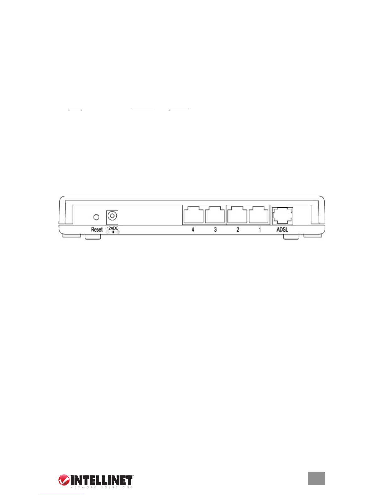
Rear Panel
Reset button: This can be used either to reset the router or to restore the factory
default settings. Press the button (using a pencil tip can help) and hold it in for
less than five seconds to re-boot the router and save any configurations that
have been set up.
If problems persist after the simple re-boot — or if you’ve forgotten your
password — hold the button in for longer than five seconds to reset the router
to its factory default settings.
NOTE: The factory default settings will replace any others that have been
configured.
Power outlet: The 12 VDC / 0.5 A power adapter included with the device is
connected here.
LAN ports: The four local area network (LAN) ports are for connections to PCs,
LANs, printers, servers, hubs and so forth.
ADSL: The enclosed RJ-11 phone line connects this outlet to an ADSL/telephone
network.
5
HARDWARE
Page 6

Setup/InStAllAtIon
Once you’re familiar with the front and rear panels of the ADSL2+ Broadband
Modem Router, the setup and installation of the device is easy.
1. From the ADSL port, connect the router to your ADSL network using the
RJ-11 telephone cable provided.
2. From any of the LAN ports, connect the router to your PC, hub, switch or
other component using the Ethernet Cat5 RJ-45 cable provided.
3. Connect the router’s power outlet to a power source using the power adapter
provided. NOTE: Use only the power adapter included with this device.
4. Check that the green ADSL LED is on, indicating a successful connection.
If the ADSL LED is blinking — indicating that no connection has been
made — contact your Internet service provider.
3. SoftwAre/Setup wIzArD
This router provides a setup wizard used to configure the ADSL settings. This
wizard collects and enters ADSL settings from some Internet service providers (ISPs)
simply by selecting the ISP when prompted. If you cannot find your particular ISP
listed in the wizard, refer to the Quick Start instructions in the Web Management
Configuration section.
Before starting:
• Make sure the ADSL cable is connected to the router correctly. When the
ADSL cable is working normally, the ADSL LED will be on.
• Uninstall all dial-up programs previously installed for the USB modem or
other dial-up devices.
• It is recommended that the router first be configured with the Ethernet cable
connected prior to setting the wireless functions.
NOTE: This setup wizard can be run in Windows 98SE, Me, 2000 or XP. The
following procedures represent Windows XP, but are similar for 98SE/Me/2000.
1. Insert the enclosed setup CD (featuring the setup wizard) into your CD-ROM
drive. The Autorun.exe program should be executed automatically. If not,
run Autorun.exe manually from the “Autorun” folder on the CD.
2. Click on “Setup Wizard” when the
initial menu appears on screen. The
wizard will search for the router. If the
router can’t be found, enter the IP
address and the password of the
router, then click “Next” to search
again.
6
SOFTWARE/SETUP WIZARD
Page 7
3. The following instructions are based on the successive prompts that will
appear. First, select the country in which the router is being installed, then
click “Next.”
4. Select your ISP.
5. If needed, enter the username and password provided by your ISP, then
click “Next.”
6. When the Settings Overview screen appears, click “Save,” which will
reboot the router.
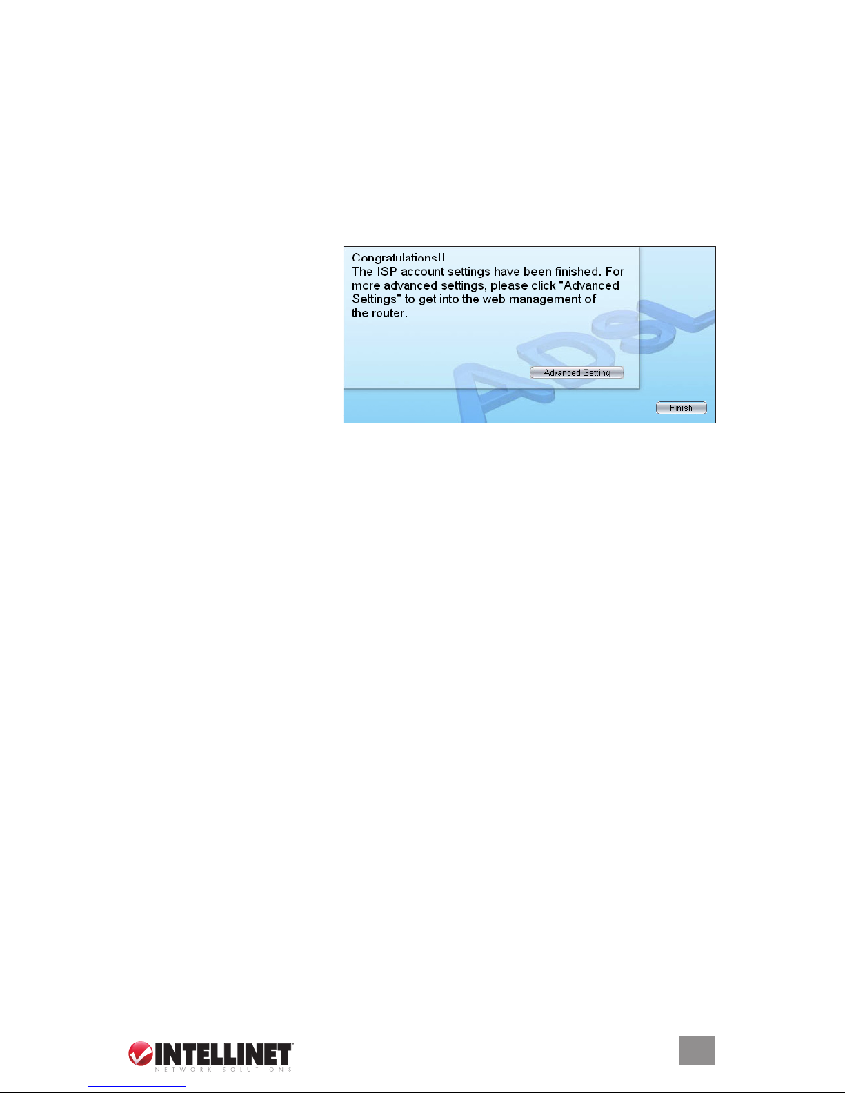
After saving and rebooting,
the ISP settings are complete.
Click “Finish” to close the
setup wizard.
To configure additional
settings, click “Advanced
Settings” and proceed to the
next section.
NOTE: To use the router to access the Internet, the IP address of each PC
has to be set in the same subnet as the router. This wizard will help to set the
proper IP address(es).
NOTE: By default, the router’s DHCP server is enabled. If it is disabled before
running the setup wizard, the wizard will automatically enable it.
4. Ip ADDreSS SettIngS
As noted above, to use the router to access the Internet, the PCs in the network
must have an Ethernet adapter installed and be connected to the router either
directly or through a hub or switch. The TCP/IP protocol of each PC has to be
installed, and the IP address of each PC has to be set in the same subnet as
the router.
The router’s default IP address is 192.168.2.1; the subnet mask is 255.255.255.0.
PCs can be configured to obtain an IP address automatically through the DHCP
server of the router or a fixed IP address in order to be in the same subnet as the
router. By default, the DHCP server of the router is enabled and will dispatch an
IP address to the PC from between 192.168.2.100 and 192.168.2.200. It is
strongly recommended that IP addresses be obtained automatically.
This section explains how to configure a PC so that it can obtain an IP address
automatically for Windows 95/98/Me, 2000 or NT operating systems. For
other operating systems (Macintosh, Sun, etc.), follow the manual of the operating
system.
7
IP ADDRESS SETTINGS
Page 8
Windows XP
1. Click “Start,” open the control panel and then double-click “Network
Connections.” The Network Connections window will appear.
2. Right-click on the Local Area Connection icon and select Properties. The Local
Area Connection window will appear.
3. Check the list of Network Components. You should see Internet Protocol
(TCP/IP) on your list. Select it and
click “Properties.”
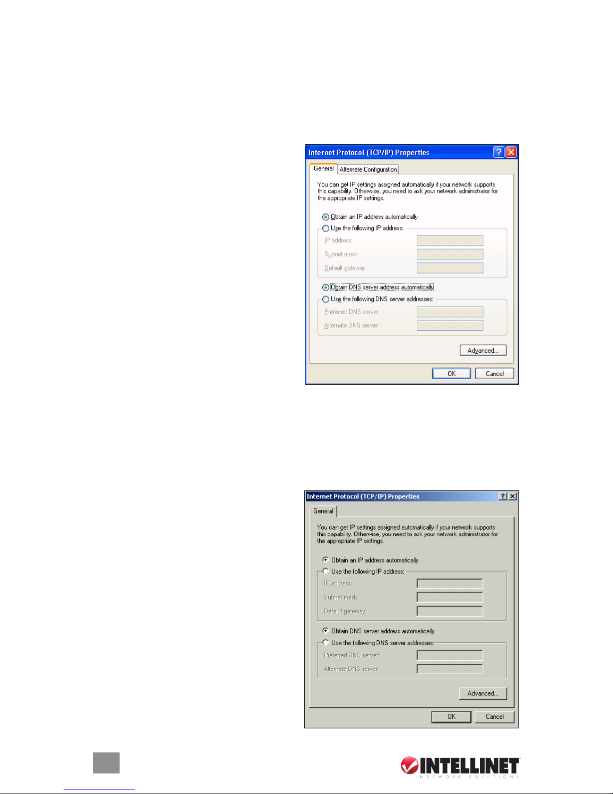
4. In the Internet Protocol (TCP/IP)
Properties window, select “Obtain
an IP address automatically” and
“Obtain DNS server address
automatically.”
5. Click “OK” to confirm the setting.
Your PC will now obtain an IP
address automatically from the
router’s DHCP server.
NOTE: Make sure the router’s DHCP
server is the only one available on
your LAN.
Windows 2000
1. Click “Start” and select Settings, then click “Control Panel.” The Control Panel
window will appear.
2. Double-click on the Network and Dial-up Connection icon. In the Network
and Dial-up Connection window, double-click on the Local Area Connection
icon. The Local Area Connection
window will appear.
3. In the Local Area Connection
window, click “Properties.”
4. Check your list of Network
Components. You should see
Internet Protocol (TCP/IP) on your
list. Select it and click “Properties.”
5. In the Internet Protocol (TCP/IP)
Properties window, select “Obtain
an IP address automatically” and
“Obtain DNS server address
automatically.”
6. Click “OK” to confirm the setting.
8
IP ADDRESS SETTINGS
Page 9
Your PC will now obtain an IP address automatically from your router’s
DHCP server.
NOTE: Make sure the router’s DHCP server is the only one available on your LAN.
Windows 95/98/Me
1. Click “Start” and select Settings, then click “Control Panel.” The Control
Panel window will appear.
2. Double-click on the Network icon. The Network window will appear.
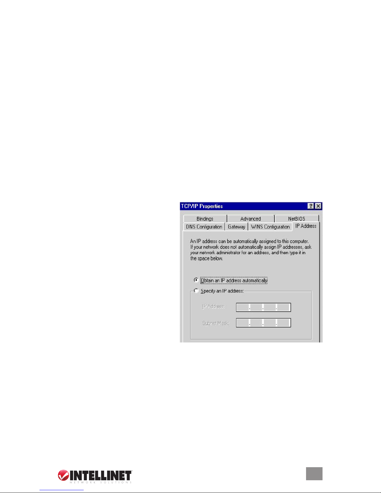
3. Check your list of Network Components. If TCP/IP is not installed, click
“Add” to install it now. If TCP/IP is installed, go to Step 6.
4. In the Network Component Type dialog box, select “Protocol” and click “Add.”
5. In the Select Network Protocol dialog box, select “Microsoft and TCP/IP,”
then click “OK” to start installing the TCP/IP protocol. You may need your
Windows CD to complete the installation.
6. After installing TCP/IP, go back to the Network dialog box. Select TCP/IP
from the list of Network Components and then click “Properties.”
7. Click on each of the tabs and
verify the following settings:
Bindings: Check “Client for
Microsoft Networks” and “File
and printer sharing for Microsoft
Networks.”
Gateway: Leave all fields blank.
DNS Configuration: Select
“Disable DNS.”
WINS Configuration: Select
“Disable WINS Resolution.”
IP Address: Select “Obtain IP
address automatically.”
8. Reboot the PC. The PC will now
obtain an IP address automatically from your router’s DHCP server.
NOTE: Make sure the router’s DHCP server is the only one available on your LAN.
Windows NT
1. Click “Start” and select Settings, then click “Control Panel.” The Control
Panel window will appear.
2. Double-click on the Network icon. The Network window will appear.
3. Check your list of Network Components. If TCP/IP is not installed, click
“Add” to install it now. If TCP/IP is installed, go to Step 5.
9
IP ADDRESS SETTINGS
Page 10
4. In the Select Network Protocol window, select the TCP/IP Protocol and
click “OK” to install the TCP/IP protocol. You may need your Windows CD
to complete the installation.
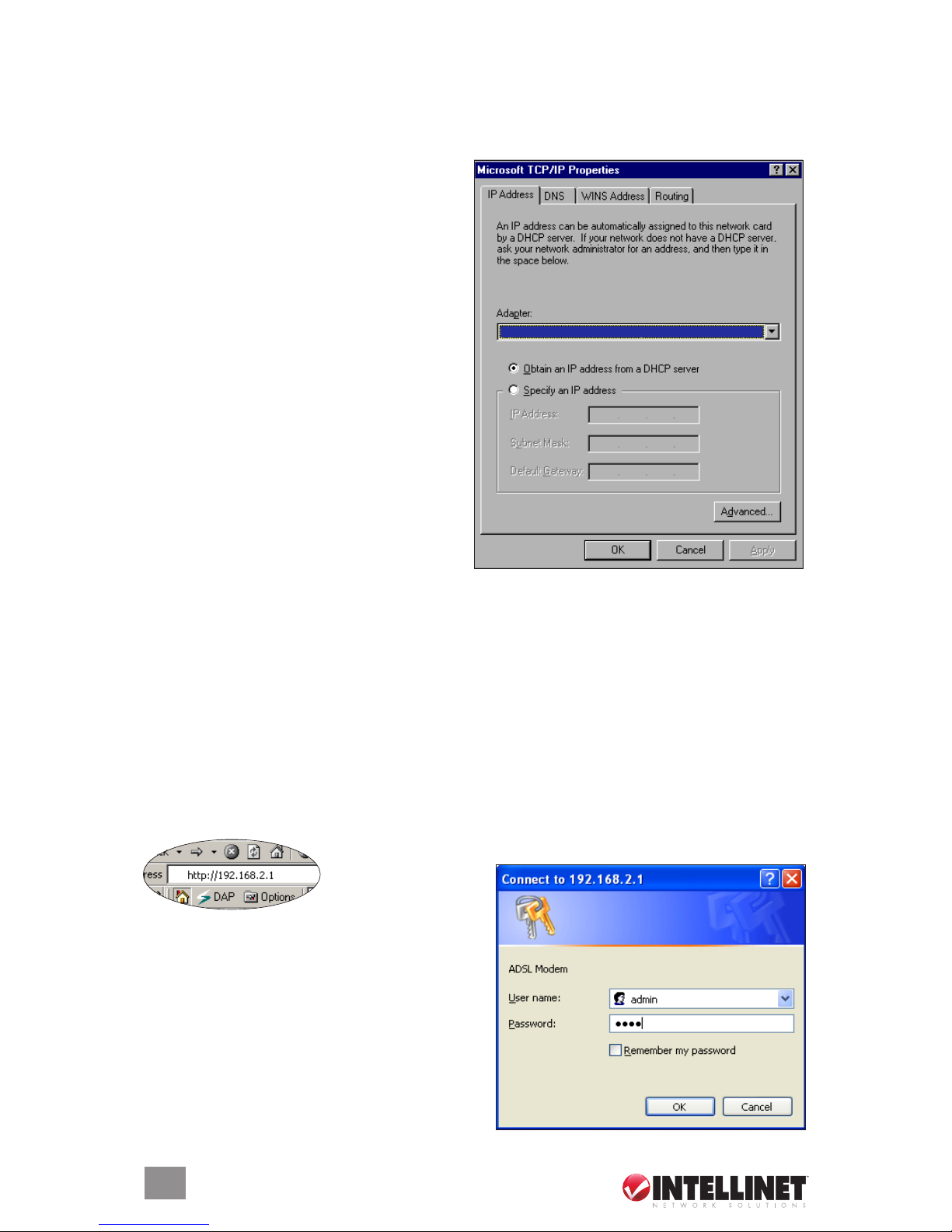
5. After you install TCP/IP, go back to the Network window. Select TCP/IP
from the list of Network Protocols,
then click “Properties.”
6. Click on each of the tabs and
verify the following settings:
IP Address: Select “Obtain an IP
address from a DHCP server.”
DNS: Leave all fields blank.
WINS: Leave all fields blank.
Routing: Leave all fields blank.
7. Click “OK” to confirm the setting.
Your PC will now obtain an IP
address automatically from your
router’s DHCP server.
NOTE: Make sure the router’s DHCP
server is the only one available on your
LAN.
5. web mAnAgement
ConfIgurAtIon
After configuring the PC(s) to obtain the IP address(es) automatically, the router’s
DHCP server will automatically give LAN clients an IP address. By default, the router’s
DHCP server is enabled so that an IP address can be obtained automatically.
Once the PC has obtained an IP address from the router, enter the default IP
address 192.168.2.1 (the router’s IP address) into the
PC’s Web browser
and press “Enter.”
The login screen will appear. Enter the
username and password, then click “OK”
to login. By default, the username is
“admin” and the password is “1234.”
NOTE: For security reasons, it is
recommended that the password be
changed as soon as possible.
Click “OK” to continue.
10
IP ADDRESS SETTINGS
INTELLINET NETWORK SOLUTIONS MIMO Wireless Turbo G USB Adapter
Page 11

11
The Home Page screen appears, displaying seven instructional options: Quick
Start, Interface Setup, Advanced Setup, Access Management, Maintenance,
Status and Help.
quICk StArt
The Quick Start section is designed to get you using the router as quickly as
possible. Before configuring the router, check with your ISP (Internet service
provider) as to what kind of service is provided (examples shown below).
1. Click “Run Wizard” to start the configuration; click “Next” to continue.
2. Set and confirm the new password; click “Next” to continue.
3. Select the time zone; click “Next” to continue.
4. Select your Internet connection type (as directed by your ISP); click “Next”
to continue.
5. Enter the data provided by your ISP. For details on each setting, see the
Interface Setup section below. Click “Next” to continue.
6. Restart your ADSL router. Click “Next” to save the settings and restart the
router.
WEB MANAGEMENT CONFIGURATION
PPPoE VPI/VCI, VC-based/LLC-based multiplexing, Username,
Password (and Service Name).
PPPoA VPI/VCI, VC-based/LLC-based multiplexing, Username,
Password.
RFC1483 Bridged VPI/VCI, VC-based/LLC-based multiplexing to use
Bridged Mode.
RFC1483 Routed VPI/VCI, VC-based/LLC-based multiplexing, IP Address,
Subnet Mask, Gateway Address and Domain Name
System (DNS) IP Address (a fixed IP Address).
Page 12

InterfACe Setup
Internet
ATM VC
Virtual Circuit: This is defined either as VPI (Virtual Path Identifier) or VCI
(Virtual Channel Identifier).
VPI: This is a virtual path that determines the way an ATM cell should be
routed. The VPI is an 8-bit (in UNI) or 12-bit (in NNI) number that is included
in the header of an ATM cell. The valid range for the VPI is 0 to 255. Enter the
VPI assigned by the ISP.
VCI: This is the label given to an ATM VC to identify it and determine its destination.
The VCI is a 16-bit number that is included in the header of an ATM cell. The valid
range for the VCI is 32 to 65535. Enter the VCI assigned by the ISP.
ATM QoS: There are four options here.
• CBR (Constant Bit Rate) – This class is used for emulating circuit switching.
The cell rate is constant with time. Select CBR to specify fixed (always on)
bandwidth for voice or data traffic.
• UBR (Unspecified Bit Rate) – Select UBR for applications that are non-time
sensitive, such as email.
• rtVBR (real-time Variable Bit Rate) – This class is similar to nrtVBR, but is
designed for applications that are sensitive to cell-delay variation. Examples
12
WEB MANAGEMENT CONFIGURATION
Page 13

13
for real-time VBR are voice with speech activity detection (SAD) and interactive
compressed video.
• nrtVBR (non-real-time Variable Bit Rate) – This class allows users to send traffic
at a rate that varies with time depending on the availability of user information.
Statistical multiplexing is provided to make optimum use of network resources.
Multimedia email is an example of nrtVBR.
PCR: This is the maximum rate at which the sender can send cells. Divide the DSL
line rate (bps) by 424 (the size of an ATM cell) to find the PCR (Peak Cell Rate).
SCR (Sustain Cell Rate): This is the average rate, as measured over a long
interval, in the order of the connection lifetime.
MBS (Maximum Burst Size): This refers to the maximum number of cells that can
be sent at the peak rate. Enter the MBS value, which must be less than 65535.
ENCAPSULATION — The router can be connected to your Internet service
provider in the following ways.
Dynamic IP Address: This automatically obtains an IP address from your ISP.
Static IP Address: This uses a static IP address. Your ISP provides a static IP
address to access Internet services.
PPPoE/PPPoA: PPPoE (PPP over Ethernet) and PPPoA (PPP over ATM) are common
connection methods used for xDSL.
Bridged Mode: This is a common connection method used for xDSL modem.
DYNAMIC IP ADDRESS/STATIC IP ADDRESS/PPPoE-PPPoA/BRIDGED MODE —
Based on the ISP type selected above, the Web page will present fields to be
filled in from among the following parameters.
User Name: Enter the username exactly as assigned by your ISP.
Password: Enter the password that your ISP has assigned to you.
Encapsulation: Check with your ISP for the method of multiplexing. In Bridged Mode,
select “1483 Bridged IP LLC” or “1483 Bridged IP VC-Mux.” In PPPoE/PPPoA
mode, select “PPPoE LLC,” “PPPoE VC-Mux,” “PPPoA LLC” or “PPPoA VC-Mux.”
Connection: There are two options here.
• Always On – The connection will always be kept on. If the connection is
interrupted, the router will re-connect automatically.
• Connect On-Demand – Only connect when you want to surf the Internet.
“Close if idle for xx minutes” is set to stop the connection when the network
traffic is not sending or receiving after an idle time.
TCP MSS Option: This enables the configuration of the maximum segment size
(MSS) for transient packets that traverse a router, specifically TCP segments in the
SYN bit set when PPPoE is being used in the network. Specify the MSS range
from 100 to 1452 bytes, or 0 bytes as the default value.
WEB MANAGEMENT CONFIGURATION
Page 14

Get IP Address: Choose “Static” or “Dynamic IP Address.” If “Static IP” is
selected, set the IP address, subnet mask and gateway obtained from your ISP.
Static IP Address: Enter the IP address assigned by your ISP.
IP Subnet Mask: Enter the subnet mask assigned by your ISP.
Gateway: Enter the gateway assigned by your ISP.
NAT: Network Address Translation (NAT) is an Internet standard that enables a
local-area network (LAN) to use one set of IP addresses for internal traffic and
a second set of addresses for external traffic. When NAT is enabled, the router
will help to make all the necessary IP address translations in order for the PC
connected to the router to access the Internet.
Default Route: When this is enabled, all the packets for destinations not known
by the router’s routing table are sent to the default route. By default, it is enabled.
TCP MTU Option: The Maximum Transmission Unit (MTU) is the maximum size
of each packet in any transmission within the network. Specify the MTU range
from 100 to 1500 bytes, or 0 bytes as the default value.
Dynamic Route: Dynamic routing allows routing tables in routers to change
as the possible routes change. This router supports RIP1, RIP2-B and RIP2-M
protocols for dynamic routing. After the RIP protocol is selected, choose the RIP
direction from among “None,” “Both,” “IN Only” or “OUT Only.”
Multicast: To specify the method of transmitting data simultaneously to many
receivers, select “IGMP v1” or “IGMP v2” as the multicast protocol. Or, select
“Disabled” to disable the function.
LAN
14
WEB MANAGEMENT CONFIGURATION
Page 15

ROUTER LOCAL IP
IP Address: Enter the IP address of the ADSL router for local access to the
router’s Web page. By default, the IP address is 192.168.2.1.
IP Subnet Mask: Enter the subnet mask of the ADSL router. By default, the
subnet mask is 255.255.255.0.
Dynamic Route: Dynamic routing allows routing tables in routers to change
as the possible routes change. This router supports RIP1, RIP2-B and RIP2-M
protocols for dynamic routing. After the RIP protocol is selected, choose the RIP
direction from among “None,” “Both,” “IN Only” or “OUT Only.”
Multicast: To specify the method of transmitting data simultaneously to many
receivers, select “IGMP v1” or “IGMP v2” as the multicast protocol. Or, select
“Disabled” to disable the function.
DHCP
DHCP: The DHCP server can be enabled or disabled. By enabling the DHCP
server, the router will automatically assign your LAN clients an IP address. If the
DHCP is not enabled, LAN clients’ IP addresses need to be manually set.
Starting IP Address: If the DHCP server is enabled, set the “Starting IP Address,”
which will be the first IP address assigned to the LAN client. By default, the starting
IP address is 192.168.2.100.
IP Pool Count: A particular IP address range can be selected for your DHCP
server to issue IP addresses to your LAN clients. By default, the IP pool count is
100. The IP range is from 192.168.2.100 to 192.168.2.199.
Lease Time: In this setting, the time period during which the DHCP server lends
IP addresses to your LAN clients can be specified. The DHCP will change your
LAN clients’ IP addresses when this time threshold period is terminated.
DNS Relay: A Domain Name System (DNS) server is like an index of IP and
Web addresses. If you type a Web address into your browser, such as “www.
router.com,” a DNS server will find that name in its index and the matching IP
address. Select “Use Auto Discovered DNS Server Only” to auto-set the DNS
server. If there is a DNS server that you would rather use, select “Use Discovered
DNS Server Only” and specify the IP address of that DNS server.
Primary DNS Server: Enter the ISP’s DNS server IP address or specify your
own preferred DNS server IP address.
Secondary DNS Server: This is optional. You can enter another DNS server’s
IP address as a backup. The secondary DNS will be used should the primary
DNS fail.
15
WEB MANAGEMENT CONFIGURATION
Page 16

ADvAnCeD Setup
Firewall
Firewall: Selecting “Enabled” protects against SYN flooding attack, Ping of
Death, Teardrop and Land attack.
SPI: Selecting “Enabled” means that all traffic initiated from a WAN site will
be blocked, including DMZ, Virtual Server, etc.
Routing
ROUTING TABLE LIST — The current routing table of the router can be viewed
here. To add another routing rule, click “ADD ROUTE.”
Dest IP: Show the IP address of the destination LAN.
Mask: Show the subnet mask of the destination LAN. If it shows “8,” the subnet
mask is “255.0.0.0”; “16” means the subnet mask is “255.255.0.0”; “24”
means the subnet mask is “255.255.255.0.”
Gateway IP: This is the IP of the neighbor router that this router should
communicate with on the path to the destination LAN.
Metric: This is the number of hops (routers) to pass through to reach the destination
LAN. It must be between 1 and 15.
Device: Show the interface that goes to the next hop (router), such as a LAN port.
Use: This is the counter for access time.
Edit: This is for editing the route, and is not shown for the system default route.
Drop: This is for dropping the route, and is not shown for the system default route.
16
WEB MANAGEMENT CONFIGURATION
Page 17

ADD ROUTE — If another router with a LAN-to-LAN connection is part of the
configuration, it may be necessary to create a static routing on the router that is
the gateway to the Internet.
Destination IP Address: Enter the IP address of the destination LAN.
IP Subnet Mask: Enter the subnet mask address of the destination LAN.
Gateway IP Address: This is the gateway IP address where packets are sent.
Metric: This is the number of hops (routers) to pass through to reach the destination
LAN. It must be between 1 and 15.
Announced in RIP: Select “Yes” and this routing path will be propagated to
other hosts through RIP (routing information protocol) broadcasts. Select “No”
and this routing path will be kept private, not to be included in RIP broadcasts.
NAT
NAT — Network Address Translation (NAT) allows multiple users at your local site
to access the Internet through a single or multiple public IP address(es). NAT provides
firewall protection from hacker attacks and has the flexibility to let you to map private
IP addresses to public IP addresses for key services such as Web sites and FTP.
Virtual Circuit: VPI (virtual path identifier) and VCI (virtual channel identifier)
define a virtual circuit.
NAT Status: The activated or deactivated status for NAT will be shown here.
Number of IPs: Select “Single” if you only have a public IP address. Select
“Multiple” if you have multiple IP addresses.
17
WEB MANAGEMENT CONFIGURATION
Page 18

DMZ — The DMZ host is a local computer exposed to the Internet. By setting
a particular internal IP address as the DMZ host, all incoming packets will be
checked by the firewall and NAT algorithms, then passed to the DMZ host. For
example, if you have a local client PC that cannot run an Internet application
(e.g., games) properly from behind the NAT firewall, you can open the client
up to unrestricted two-way Internet access by defining a DMZ host.
DMZ setting for: Shows the
DMZ setting is for single or
multiple IP addresses.
DMZ: Enable/disable DMZ.
DMZ Host IP Address: Enter
a static IP address to the DMZ
host. This IP address will be
exposed to the Internet.
VIRTUAL SERVER — The Virtual Server lets different servers/clients in a LAN handle
different service/Internet application types from the Internet. Computers use numbers
called port numbers to recognize a particular service/Internet application type. Virtual
Server allows you to re-direct a particular service port number (from the Internet/
WAN) to a particular LAN private IP address and its service port number.
Virtual Server for: Shows the setting is for single or multiple IP addresses.
Rule Index: Choose the rule number.
Start Port Number: Enter the start port number.
18
WEB MANAGEMENT CONFIGURATION
Page 19

End Port Number: Enter the end port number.
Local IP Address: A static IP address for the server should be entered here. If obtained
from the DHCP server, the IP address may be changed dynamically, causing a
problem on this feature. Assign a static IP address to the server and make sure that
the IP address is not in the range of IP addresses that the DHCP server will assign.
ADSL
ADSL
ADSL Mode: The default setting is
“Auto Sync-Up.” This automatically
detects the ADSL mode, including
ADSL2+, ADSL2, G.DMT, T1.413
and G.lite. If you’re not sure how
to select the ADSL mode, contact
your ISP.
ADSL Type: Ask your ISP what
ADSL type of DSLAM device they
use. (The Digital Subscriber Line Access Multiplexer, or DSLAM, links many of a
phone company’s customer DSL connections to a single high-speed ATM line.)
ACCeSS mAnAgement
ACL
To restrict users from accessing certain Internet applications/services (Web sites,
email, FTP, etc.), configure those settings here. The access control list (ACL) lets you
define the traffic type permitted in a LAN or WAN. You can control which computer
can have access to these services by entering the IP address of the computer.
19
WEB MANAGEMENT CONFIGURATION
Page 20

ACL: When this is “Activated,” make sure that the available applications/
services are designated or access to all the services will be denied.
ACL Rule Index: This is the item number to record the setting rule.
Secure IP Address: The default 0.0.0.0 allows any user to remotely manage the
router. Type an IP address to restrict access to a user with a matching IP address.
Application: Choose the services that you permit to be used in your LAN or
WAN interface. Options include “Web,” “Telnet,” “Ping,” “FTP” and “SNMP.”
Interface: Select the interface that will allow use of the services above. Options
are “LAN,” “WAN” or “Both.”
IP Filter
To deny some users access to the router’s Web management, enter the IP
addresses here. The default IP 0.0.0.0 lets any user remotely manage the router.
IP FILTER SET EDITING
IP Filter Set Index: This is the item number to record the setting.
Interface: Select which channel (PVC) to configure.
Direction: Select access to (“Outgoing”) or from the Internet (“Incoming”) or “Both.”
IP FILTER RULE EDITING
IP Filter Rule Index: This is the item number to record the setting rule.
20
WEB MANAGEMENT CONFIGURATION
Page 21

21
Active: Select “Yes” to enable the current rule; “No” to cancel the current rule.
Source IP Address: Enter the start IP address that will be monitored.
Subnet Mask: Enter the subnet mask based on the source IP address.
Port Number: LAN users employ port numbers to differentiate network applications
(e.g., “21” is for FTP service). The port number range is from 0 to 65535. It is
recommended that this option be configured by an advanced user.
Destination IP Address: Enter the start IP address that will be monitored.
Subnet Mask: Enter the subnet mask based on the destination IP address.
Port Number: This is the port or port ranges that define the application.
Protocol: This is the packet protocol type used by the application. Select
“TCP,” “UDP” or “ICMP.” (For FTP service, for example, select “TCP.”)
Rule Unmatched: Select action for traffic not matching the current rule. “Forward”
is to let it pass through; “Next” is to check it by the next rule.
IP FILTER LISTING — This lists the IP filter rules that have been configured. The
settings can be reviewed here.
SNMP
Simple Network Management Protocol (SNMP) is a popular protocol for network
management. It is used for collecting information and configuring the network
devices. This router supports an SNMP agent function, which allows a manager
station to manage and monitor the router through the network.
Get Community: Enter the password for the incoming Get and GetNext
requests from the management station.
Set Community: Enter the password for a Set request to configure the router.
UPnP
When the Universal Plug and Play (UPnP) function is enabled, the router can
be detected by a UPnP-compliant system such as Windows XP. The router
will be displayed in the Neighborhood of Windows XP, so you can directly
double-click or right-click the router and select “Invoke” to configure the router
through a Web browser.
WEB MANAGEMENT CONFIGURATION
Page 22

22
UPnP: Select “Activated” or “Deactivated.”
Auto-configured: This allows UPnP-enabled applications to automatically
configure the router so that they can communicate through the router. For
example, by using a NAT traversal, UPnP applications automatically reserve
a NAT forwarding port in order to communicate with another UPnP-enabled
device, eliminating the need to manually configure port forwarding for the
UPnP-enabled application.
DDNS
DDNS allows mapping of the static domain name to a dynamic IP address.
Obtain an account, password and static domain name from the DDNS service
provider.
Dynamic DNS: Activate or deactivate the DDNS function.
Service Provider: This router supports DynDNS service provider.
My Host Name: Enter the domain name assigned to your router by the ISP.
E-mail Address: Enter the email address assigned by DDNS service provider.
Username: Enter your username.
Password: Enter the password set for the DDNS service.
Wildcard Support: Enable or disable the wildcard to stand for some
characters.
WEB MANAGEMENT CONFIGURATION
Page 23

23
mAIntenAnCe
ADMINISTRATOR
Username: The username of the router is “admin” by default.
New Password: Enter up to 30 characters for the new password.
Confirm Password: Enter the new password again to confirm the setting.
TIME ZONE
Time Zone allows the router to set its time (affecting functions like System Log).
Current Date/Time: Show the current date/time of the router.
Synchronize time with: There are three options here.
• NTP Server Automatically – Synchronize the time with an NTP server.
• PC’s Clock – Set the time the same as your computer.
• Manually – Set the time manually.
Time Zone: Select the time zone of the country and/or region you are in. The
router will set its time based on your selection.
Daylight Saving: Enable this option if it is currently daylight saving time.
NTP Server Address: Enter the IP address of your time server.
WEB MANAGEMENT CONFIGURATION
Page 24

24
FIRMWARE
If new firmware is available to update some features, perform the upgrade here.
New Firmware Location: Type in the new firmware location or click “Browse.”
Browse: Click “Browse” to find the new firmware.
Upgrade: Click “Upgrade” to begin the upgrade process. Once the router restarts,
the process is complete. It might take several minutes — don’t turn off power to the
router during upgrading.
SYSTEM RESTART
Click “Restart” to
restart the router.
To restore factory
defaults, select
“Factory Default
Settings” (or
press and hold
in the reset
button for 5 seconds or more).
DIAGNOSTICS
Diagnose the connectivity of the LAN and WAN networks here.
WEB MANAGEMENT CONFIGURATION
Page 25

25
StAtuS
DEVICE
INFORMATION
Check or confirm
device information
here, including
firmware versions,
MAC addresses,
LAN and WAN
settings, and the
ADSL line status.
SYSTEM LOG
On this page, display system logs accumulated up to the present time. The
logs can also be saved for future review.
WEB MANAGEMENT CONFIGURATION
Page 26

26
STATISTICS
This screen show the statistics of transmit and receive packets on the LAN port
and the ADSL line.
6. troubleShootIng
Problem: The LAN LED on the front panel does not light up.
1. Check the Ethernet cable connections between the router and PC or hub.
2. Check for faulty Ethernet cables.
3. Make sure your computer’s Ethernet card is working properly.
If these steps fail to correct the problem, contact your local distributor for assistance.
Problem: The ADSL LED on the router’s front panel does not light up.
1. Check the phone wire and connections between the DSL port and wall jack.
2. Make sure that the telephone company has checked your phone line and
has set it up for DSL service.
3. Reset your ADSL line to re-initialize your link to the DSLAM.
If these steps fail to correct the problem, contact your local distributor for assistance.
Problem: Unable to access the router’s Web management.
1. Make sure you are using the correct IP address for the router (see below).
2. Ensure the PC and router’s IP addresses are on the same subnet for LAN access.
3. If the router’s LAN IP address was changed, enter the new one as the URL.
NOTE: To check that the current IP
addresses of your PC and the router are
in the same subnet, follow these steps:
1. Click “Start” and select “Run.”
2. Type in “cmd” and click “OK.”
3. Type in “ipconfig /all” and click
“Enter.”
TROUBLESHOOTING
Page 27

27
As shown above, the PC’s IP address is 192.168.2.111; its subnet mask is
255.255.255.0; and its MAC address is Physical Address...: 00-00-E2-82-C3-AD.
Problem: The login username or password is forgotten.
1. If the password has been changed, then forgotten, the default configuration
file needs to be uploaded. This will erase all custom configurations and
restore all of the factory defaults, including the password.
2. Press the Reset button for five seconds, then release it. When the LAN LED
begins to blink, the defaults have been restored.
3. Make sure the computer’s Ethernet card is working properly.
Problem: Unable to access the router’s Web management after activating ACL.
1. When ACL is activated, the ACL rule needs to be set to allow some users
to use some services. Check that the rules have been set. If not, all the users
are denied use of any of the services from the LAN or WAN.
2. If still unable to access, reset the router to restore to defaults.
3. After restarting the router, login with the default IP address 192.168.2.1.
Problem: Initialization of the ADSL connection failed.
1. Check the cable connections between the ADSL port and the wall jack. The
ADSL LED on the rear panel of the router should be on.
2. Check that the VPI, VCI, type of encapsulation and type of multiplexing settings
are the same as those received from the ISP.
3. Restart the router. If the problem persists, it may be necessary to verify the
VPI, VCI, type of encapsulation and type of multiplexing settings with the ISP.
Problem: Unable to obtain a WAN IP address from the ISP.
1. The ISP provides the WAN IP address after authenticating you, which may
be through the username and password, the MAC address or the hostname.
2. The username and password apply to PPPoE and PPoA encapsulation only. Make
sure the correct service type, username and password have been entered.
Problem: The Internet connection disconnects.
1. Check the schedule rules.
2. If PPPoA or PPPoE encapsulation is being used, check the idle time-out setting.
3. Contact the ISP.
TROUBLESHOOTING
Page 28

28
7. gloSSAry
10Base-T: An Ethernet standard for Local Area Network (LAN). 10Base-T uses
a twisted-pair cable with a maximum length of 100 meters.
AAL: ATM Adaptation Layer defines the rules governing segmentation and reassembly
of data into cells. Different AAL types are suited to different traffic classes.
ADSL: An Asymmetric Digital Subscriber Line is an asymmetrical data transmission
technology with a high traffic rate downstream and a low traffic rate upstream.
ADSL technology satisfies the bandwidth requirement of applications that demand
“asymmetric” traffic; e.g., Web surfing, file downloading and video-on-demand.
ATM: Asynchronous Transfer Mode is a Layer 2 protocol supporting high-speed
asynchronous data with advanced traffic management and quality-of-service features.
bps: Bits per second, a standard measurement of digital transmission speeds.
Bridge: A device that connects two or more physical networks and forwards
packets between them. Bridges can usually be made to filter packets; that is,
to forward only certain traffic. Related devices are repeaters, which simply
forward electrical signals from one cable to another, and full-fledged routers
that make routing decisions based on several criteria.
CPE: Customer Premises Equipment, such as an ADSL router or USB modem.
Default Gateway (Router): Every non-router IP device needs to configure a
default gateway’s IP address. When the device sends out an IP packet, if the
destination is not on the same network, the device has to send the packet to its
default gateway, which will then send it out toward the destination.
DHCP: A Dynamic Host Configuration Protocol automatically gives every
computer on your home network an IP address.
DNS Server IP Address: The Domain Name System (DNS) allows Internet servers to
have a domain name (e.g., www.Broadbandrouter.com) and one or more IP
addresses (e.g., 192.34.45.8). A DNS server keeps a database of Internet servers
and their respective domain names and IP addresses so that when a domain name
is requested (as in typing “Broadbandrouter.com” into an Internet browser) the user is
sent to the proper IP address. The DNS server IP address used by the computers on
a home network is the location of the DNS server the ISP has assigned.
DSL: Digital Line Subscriber (DSL) technology provides high-speed access over twistedpair cable for connection to the Internet and LAN interfaces, and to broadband
services such as video-on-demand, distance learning and video conferencing.
Ethernet: A standard for computer networks, Ethernet networks are connected by
special cables and hubs or switches, and move data around at up to 10/100 Mbps.
FTP: File Transfer Protocol is the Internet protocol (and program) used to transfer
files between hosts.
GLOSSARY
Page 29

29
Idle Timeout: After there is no traffic to the Internet for a pre-configured amount
of time, Idle Timeout automatically disconnects from it.
ISP: The Internet Service Provider is a business that provides connectivity to the
Internet for individuals, businesses and organizations.
ISP Gateway Address: This is an IP address for the Internet router located at
the ISP’s office.
LAN: A Local Area Network is a group of computers and devices connected in a
relatively small area (e.g., a house or office). A home network is considered a LAN.
MAC Address: A Media Access Control (MAC) address is the hardware
address of a device connected to a network. It’s a unique identifier for a device
with an Ethernet interface. It is composed of two parts: 3 bytes of data that
correspond to the manufacturer ID (unique for each manufacturer), plus 3 bytes
that are often used as the product’s serial number.
MTU: Maximum Transmission Unit.
NAT: A Network Address Translator, as defined by RFC 1631 (see RFC below),
enables a LAN network to use one set of IP addresses for internal traffic. A
NAT box, located where the LAN meets the Internet, provides the necessary IP
address translation. This helps provide a sort of firewall and allows for a wider
address range to be used internally without danger of conflict. Using the router’s
NAT capability, the Internet can be accessed from any computer on a home
network without having to purchase more IP addresses from the ISP.
Port: Network clients (LAN PC) use port numbers to distinguish one network
application/protocol from another. Common examples:
PPP: Point-to-Point-Protocol is the successor to SLIP. It provides router-to-router and
host-to-network connections over both synchronous and asynchronous circuits.
PPPoA (RFC 2364): The Point-to-Point Protocol (PPP) provides a standard method for
transporting multi-protocol data grams over point-to-point links. This document describes
the use of ATM Adaptation Layer 5 (AAL5) for framing PPP-encapsulated packets.
PPPoE (RFC 2516): This document describes how to build PPP sessions and
encapsulate PPP packets over the Ethernet. PPP over Ethernet (PPPoE) provides
the ability to connect a network of hosts over a simple bridging access device
to a remote access concentrator.
Protocol: A protocol is a set of rules for interaction agreed upon between
multiple parties so that when they interface with each other based on such a
GLOSSARY
Application Protocol Port No.
Telnet TCP 23
FTP TCP 21
SMTP TCP 25
POP3 TCP 110
H.323 TCP 1720
SNMP UCP 161
Application Protocol Port No.
SNMP Trap UDP 162
HTTP TCP 80
PPTP TCP 1723
PC Anywhere TCP 5631
PC Anywhere UDP 5632
Page 30

30
protocol, the interpretation of their behavior is well-defined and can be made
objectively, without confusion or misunderstanding.
PVC: A Permanent Virtual Circuit is a connection-oriented, permanent leasedline circuit between end stations on a network over a separate ATM circuit.
RFC: Request for Comments is a document series, begun in 1969, that describes
the Internet suite of protocols and related experiments. Not all RFCs describe
Internet standards, but all Internet standards are initially written up as RFCs.
RFC 1483: This refers to multi-protocol encapsulation over AAL-5. There are two
encapsulation methods for carrying network interconnect traffic over ATM AAL5:
1) LLC Encapsulation allows multiplexing of multiple protocols over a single ATM
virtual circuit. The protocol of a carried PDU is identified by prefixing the PDU by
an IEEE 802.2 Logical Link Control (LLC) header; 2) VC Based Multiplexing does
higher-layer protocol multiplexing implicitly by ATM virtual circuits (VCs).
Router: This is a device responsible for making decisions about which of
several paths network (or Internet) traffic will follow. To do this, it uses a routing
protocol to gain information about the network and algorithms to choose the
best route based on several criteria known as “routing metrics.”
Subnet Mask: A subnet mask, which may be a part of the TCP/IP information
provided by your ISP, is a set of four numbers (e.g., 255.255.255.0) configured
like an IP address. It is used to create IP address numbers used only within a
particular network (as opposed to valid IP address numbers recognized by the
Internet, which must be assigned by InterNIC).
TCP/IP, UDP: Transmission Control Protocol/Internet Protocol is the standard
protocol for data transmission over the Internet. Both TCP and UDP (Unreliable
Datagram Protocol) are transport-layer protocols. TCP performs proper error
detection and error recovery, and thus is reliable. UDP, on the other hand, is not
reliable. They both run on top of the IP (Internet Protocol), a network-layer protocol.
TELNET: This is the virtual terminal protocol in the Internet suite of protocols. It allows
users of one host to log into a remote host and act as normal terminal users of that host.
VCI: A Virtual Circuit Identifier is part of the ATM cell header. A VCI is a tag
indicating the channel over which a cell will travel. The VCI of a cell can be
changed as it moves between switches via signaling.
VPI: A Virtual Path Identifier is part of the ATM cell header. A VPI is a pipe for
a number of virtual circuits.
WAN: A Wide Area Network connects computers located in separate areas
(e.g., different buildings, cities, countries). The Internet is a wide area network.
Web-Based Management Graphical User Interface (GUI): Many devices
support a graphical user interface that is based on the Web browser. This
means the user can use the familiar Netscape or Microsoft Internet Explorer to
control/configure or monitor the device being managed.
GLOSSARY
Page 31

31
8. SpeCIfICAtIonS
SPECIFICATIONS
Standards
• IEEE 802.3 (10Base-T Ethernet)
• IEEE 802.3u (100Base-TX Fast Ethernet)
• ADSL2+ (ITU G.992.5) up to 24 Mbps
• ADSL2 (ITU G.992.4) splitter-less ADSL,
up to 12 Mbps
• ADSL2 (ITU G.992.3) up to 12 Mbps
• ADSL (ITU G.992.2/G.Lite) up to
1.5 Mbps
• ADSL (ITU G.992.1/G.DMT) up to
8 Mbps
• ANSI T1.413, Issue 2 (Asymmetric DSL)
General
• LAN ports: 4 RJ-45 10/100 Mbps data
ports
• LAN ports with Auto MDI/MDI-X
• Flash: 2 MB
• Memory: 8 MB SDRAM
• Throughput max.: 24 Mbps downstream,
1 Mbps upstream
• Certifications: FCC Class B, CE Mark,
RoHS
Environmental
• Dimensions: 187 (W) x 100 (D) x 30 (H) mm
(7.3 x 3.9 x 1.2 in.)
• Weight: 1.0 kg (2.2 lbs.)
• Operating temperature: 0 – 40°C
(32 – 104°F)
• Operating humidity: 10 – 90% RH,
non-condensing
• Storage temperature: 0 – 60°C
(0 – 149°F)
LEDs
• Power
• ADSL Link/Act
• LAN 1-4 Link/Act
Router
• Chipset: Trendchip
• Supported WAN connection types:
- PPP over Ethernet (RFC 2516)
- PPP over AAL5 (RFC 2364)
- Multiple Protocols over AAL5
(RFC 1483/2684)
• NAT:
- Virtual server
- Port forwarding
- DMZ (demilitarized zone)
• Firewall:
- Access control based on MAC address
- Domain blocking
- URL filter
• Supports UPNP (Universal Plug and Play)
• Supports DHCP (client/server)
• Supports VPN pass-through (IPSec, PPTP,
L2TP)
• Certifications: FCC Class B, CE Mark,
RoHS
Power
• External power adapter: 12 V DC, 0.5 A
Package Contents
• ADSL2+ Broadband Modem Router
• User manual
• Setup CD with user manual and setup
wizard
• Power adapter
• Ethernet Cat5 RJ-45 cable, 1.0 m (3 ft.)
• RJ-11 telephone cable, 1.8 m (6 ft.)
Page 32

Are you completely satisfied with this product?
Please contact your INTELLINET NETWORK SOLUTIONS™ dealer
with comments or questions.
Copyright © INTELLINET NETWORK
SOLUTIONS
All products mentioned are trademarks or registered trademarks of their respective owners.
www.intellinet-network.com
 Loading...