

Page 1

User Guide
EN
LAN TESTER
Page 2

the European WEEE directive, electrical and
According to
electronic equipment must not be disposed with consumers waste.
Its components must be recycled or disposed apart from each other.
Otherwise contaminative and hazardous substances can pollute
our environment.
You as a consumer are committed by law to dispose electrical and electronic
devices to the producer, the dealer, or public collecting points at the end of the
devices lifetime for free. Particulars are regulated in national right. The symbol
on the product, in the user's manual, or at the packaging alludes to these
terms. With this kind of waste separation, application, and waste disposal of
used devices you achieve an important share to environmental protection.
0 Safety Instruction
1.
Device always on a stable and straight Surface. In case
Put the
of falling it can be damaged.
Don’t place the Device into direct Sunlight or in Places with high
Temperature. This can damage the Device or shorten his
average useful Life.
Don’t place it in the near of Heat Sources, like Radiators or other
heat producing Devices.
Don’t expose the Device to Rain, Water, Wetness or high Humidity.
Don’t place it in the Bathroom or the Kitchen in the near of a Sink.
Avoid the direct Contact with Water.
Don’t try to open the Device.
Prior to the first use of our product make a backup of your data.
We are not liable for any loss of data, unless you can accuse us
intention or gross negligence.
In any case, liability for loss of data is limited to the effort that is
necessary to restore from existing backup copies.
Please read the Manual and Safety Instructions before using the
product for the first time. Otherwise damage can be the result.
2
Page 3

2.0 Introduction
can easily read the correct pin configuration of
Lan tester
10Base-T cable, 10Base-2 cable, RJ45/RJ11 modular cables,
258A, TIA-568A/568B and Token Ring cable etc. by comparing
one transmitting end to the corresponding receiving end. With the
remote kit it can test cable installed far away either on wall plate
or patch panel. It is easy to verify the cable continuity, open, short
and cross-connect. Lt’s affordable, so you can benefit the most.
2
.1 Specification
Test the correct pin configuration of 10Base-T, 10Base-2
x
Ethernet cable, RJ45/RJ11 modular cables, 258A, TIA
568A/568B and Token Ring Cable etc.
x Easy to read cable status and verify cable continuity, open
short and miswire.
x With remote kit, it can remotely test cable far away either on
wall plate or patch panel.
x Test the grounding
x With auto or manual scan
x Operates with 9 Volt block battery (not included)
2.2 Pac
kage Contents
x
1 x Main Tester Unit
x 1 x Remote Unit
x 2 x BNC Adapter Cables
x 1 x BNC Male/Male Adapter
x 3 x RJ45 to RJ11 Adapters
x 1 x User Manual
3
Page 4
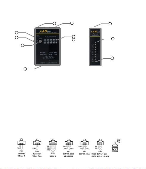
.3 Product Profile:
2
6
5
7
11
Ma
in Unit Remote Unit
1. RJ45 JACK
2. RJ45 JACK
3. LED DISPLAY FOR SOURCING END (JACK l)
4. LED DISPLAY FOR RECEIVING END (JACK 2)
5. POWER SWITCH
6. LED SCANNING MODE SWITCH
7. TEST SWITCH FOR MANUAL SCAN
8. RJ45 JACK
9. LED DISPLAY FOR RECEIVING END (SAME AS JACK 2)
10. GROUND LED FOR RECEIVING END
11. BATTERY COMPARTMENT (9V)
2
1
3
4
4
8
9
10
Page 5
3.0 OPERA
3
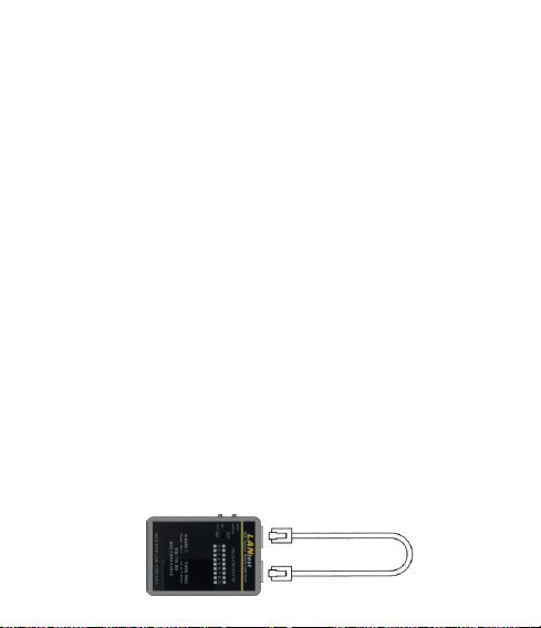
.1 Loopback Test
10Base
1. Plug one end of tested cable on sourcing of RJ45 jack
(Marked with‘Ÿ') and another end of tested cable on
remaining receiving RJ 45 jack.
2. Slide power switch on, the upper row LEDs will start to scan
in sequence if the Auto/Manual switch is set on Auto mode, or
the LED will light on pin 1 if the Auto/Manual switch is set on
Manual mode.
Note: You have to make sure the battery power is sufficient. If
3. Choose the Auto/Manual switch to be Auto scan mode or
Manual scan mode by pressing the Auto/Manual switch.
4. In this moment the corresponding LED indicators of another
row of LED will light up simutaneousIy.
5. Read out the result of LED display. It tells you the pin
configuration status of the tested cable. If you fail to read the
result in the first run of LED scan, you may read it again in the
the test switch one by one until you read the result out.
Loopback
Tes t
4
TION
-T Cable Test
battery fails to the power, the LEDs will be dimmed or
hold up or no light, and the test result will be incorrect.
Page 6
lar Cable test
Modu
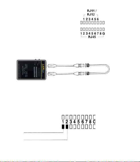
Please follow up the procedures of
10Base-T Cable Test.
However, the LED display should be
read as the right picture.
10Base-2 Cable Test
1. Plug the two attached BNC adaptor cables on both RJ45
jacks, then connect the tested cable both ends on BNC
adaptor cables.
2
. As to the remaining procedures, you may refer to 10Base-T
cable test from step 1.2. to 1.5.
Note:
1). The center pin of BNC should be read on LED 1 and
shielding pin of BNC should be read on LED 2.
BNC CENTER PIN
BNC SHIELDING
2). As the 10Base-2 cable has only two wires, we suggest you
to read the result of LED scan by manual mode.
5
Page 7
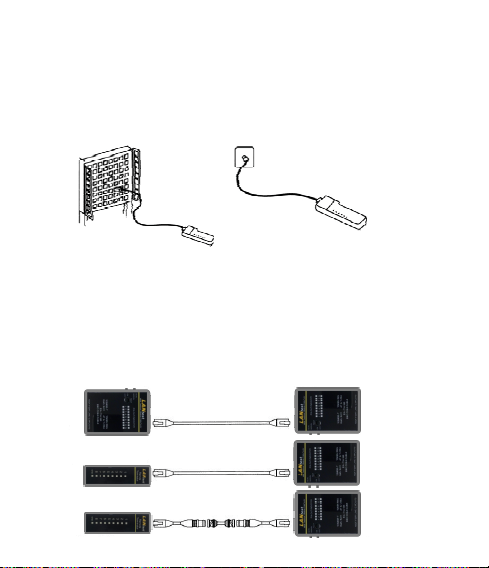
.2 Remote Test
3
. Plug one end of tested cable on the sourcing RJ45 jack
1
(Marked with‘Ÿ') of master unit and another end on the
receiving RJ45 jack of remote unit. If the tested cable has
already installed on the patch panel or wall plate, you may use
the adaptor cable to solve the connector gender problem.
Patch Panel Wall Plate
2. Now, set the Auto/manual switch on Auto mode if you work
test alone.
3. Read the test result from LED display on remote unit.
Note: The LED display on remote unit was scanned in
6
sequence corresponding to the sourcing end of master
unit.
Page 8
 Loading...