

IBC-667IR
Network Bullet Camera
Hardware Installation Guide

Package Contents
Camera Network Bullet Camera
Quick Installation Guide Brief product information and quick
installation
Software CD
Accessories - Wall mount bracket & U-shape bracket
IP Surveillance Software
Intelligent IP Installer
User Manuals
Language Pa ck s
- Metal plate for wall mount bracket
- Alignment Sticker
- Waterproof Connector
- Screw pack for sun shield &
burglarproof screw
- Screw pack for wall and ceiling
mounting
- Silica gel
- Foam tape
- 2 pin terminal blocks for power
- 8 pin terminal blocks for DI/DO
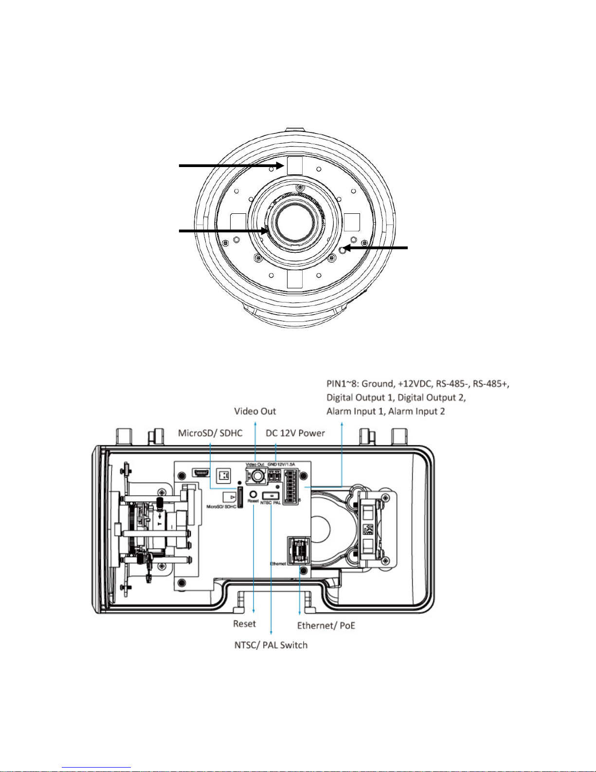
Hardware Description
IRLED
Lens
LightSensor

I/O Terminal Block Circuit
DigitalInput1/2:Max:30VDC
DigitalOutput1/2: Max:24V/100mA
I/O Terminal Block Pin Definition
PIN Definition Description Max. V/A
1
2
3
4
5
6
7
8
Ground
+ 12V DC
AUDIO_In(+)
AUDIO_Out(+) Unbalanced, 1.4Vp-p, 1Vrms, terminal block -
Digital Output 1
Digital Output 2
Digital Input 1
Digital Input 2
12V DC
Unbalanced, 1.4Vp-p, 1Vrms, terminal block
Uses an NPN transistor with the emitter connec ted to th e
GND pin. If used with an external relay, a diode must be
connected in parallel with the load for protection against
voltage transients.
Uses an NPN transistor with the emitter connec ted to th e
GND pin. If used with an external relay, a diode must be
connected in parallel with the load for protection against
voltage transients.
Connected to GND to activate, or leave floating (or
unconnected) to deactivate.
Connected to GND to activate, or leave floating (or
unconnected) to deactivate.
-
1.2W
-
100 mA
24V
100mA
24V
30V DC
30V DC

LED Indicators
LED Color Indication
Green Active network link
Network
Orange Flashing indicates network activity
Red Steady red during boot-up process
Power
Micro SD / SDHC Orange
Blue Steady blue when boot sequence has been completed
Unlit
Power Mode
Power Requirement
PoE Mode
Power Consumption
Power Requirement
Adaptor Mode
Power Consumption
When the reset button was pressed for at least 5 sec.
and camera is restarting,
Steady orange means SD card ready
Flashes orange while accessing SD card
PoE (IEEE802.3af) with Class 3
Note: While IR on, Heater and Fan will be disabled.
3.59 W, without IR/Heater/Fan
7.9 W, with max. IR on.
12V/1.5A Adaptor
Note: While IR on, Heater or Fan would be activated
automatically.
3.58 W, without IR/Heater/Fan
7.9 W, with max. IR on
9.6 W, with max. IR on / Heater on
8.87 W, with max. IR on / Heater Fan
Note: Heater will be activated while the inner temparature drops under 5C and fan over 50C.

Installing the hardware
1) Assembling sun shield and camera with two supplied screws(M3*6).
2) Fix U-shape bracket to the bottom of camera with supplied screws.
3) Insert all cables (RJ45/power cord/DIDO) into waterproof connector (M25*1.5).
4) Open the front cover and feed all cables through the screw hole of bottom cover from
outside. Connect them to sockets. Then secure the connector tightly.
5) Attach the foam tape and silica gel. (Please change a new silica gel if open the top
cover afterwards.)
6) Lock the front cover. Then secure the burglarproof screw.
7) Feed all cables through the front opening of wall mount bracket.
8) Push the spring mortise of wall mount bracket. Then hook the U-shape bracket onto
the groove of the former.
9) Secure the two screws of wall mount bracket on the other side.

Wall and Ceiling mounting
1) Attached the alignment sticker to the wall. Drill four holes into the wall. Three
holes are for the screws to affix the bracket to the wall, and one larger hole for
the cable. Push the supplied plastic anchors into the screw holes and secure the
plate with the supplied screws (T1/4”*32).
2) Fix the wall mount bracket to the plate with the supplier screws.
3) Position the camera angle by adjusting the pan and tilt.
Lens Focusing

Factory Reset
Reset: With the camera turned on, press the reset button briefly to reboot the camera,
or hold the reset button for 10 seconds to set all settings back to factory default values.
1. Connect the camera via PoE
Using a standard RJ-45 network cable, connect the bullet camera to an
IEEE802.3af/at compliant PoE switch or PoE injector.
2. Connect the camera without PoE
1. Connect the power adaptor to the dome camera
2. Using a standard RJ-45 network cable, connect the camera to a n o rmal
Ethernet Switch or Router
3. Software Installation
Insert the Installation CD into a CD or DVD drive and follow the instructions given
by the Quick Installation Guide.

INTELLINET NETWORK SOLUTIONS™ offers a complete line
of active and passive networking products.
Ask your local computer dealer for more information or visit
www.intellinet-network.com
Copyright © INTELLINET NETWORK
All products mentioned are trademarks or registered trademarks of their respective
owners.
SOLUTIONS
 Loading...