

Intellinet 561426 User Manual
INT-561426_UM-1218_REV-5.01
24-Port Gigabit Ethernet
PoE+ Web-Managed Switch
with 4 Gigabit Combo
Base-T/SFP Ports
User Manual
Model 561426
intellinetnetwork.com

2
24-Port Gigabit Ethernet PoE+ Web-Managed Switch with
4 Gigabit Combo Base-T/SFP Ports
User Manual
TABLE OF CONTENTS
INTRODUCTION .......................................................................................................................... 4
PRODUCT OVERVIEW ...............................................................................................................4
FEATURES .................................................................................................................................. 4
SPECIFICATIONS ....................................................................................................................... 4
EXTERNAL COMPONENT DESCRIPTION .................................................................................... 5
FRONT PANEL ........................................................................................................................ 5
REAR PANEL ...........................................................................................................................6
PACKAGE CONTENTS ............................................................................................................... 6
INSTALLING AND CONNECTING THE SWITCH .............................................................................6
DESKTOP INSTALLATION ..........................................................................................................6
RACKMOUNT INSTALLATION IN 19” CABINET ..........................................................................7
POWER ON THE SWITCH .......................................................................................................... 7
CONNECTION TO THE SWITCH .................................................................................................... 7
CONNECTING TO COMPUTER .................................................................................................. 7
HOW TO LOG IN TO THE SWITCH ..............................................................................................8
SAVING THE CONFIGURATION ....................................................................................................9
SWITCH CONFIGURATION ..........................................................................................................9
HOME ....................................................................................................................................... 9
PORT CONFIGURATION .........................................................................................................9
QUICK SETUP .......................................................................................................................... 10
PORT SETTINGS ....................................................................................................................... 10
BASIC CONFIG ....................................................................................................................10
PORT AGGREGATION ........................................................................................................... 12
PORT MIRRORING ................................................................................................................ 13
PORT SPEED LIMIT ................................................................................................................13
BROADCAST STORM ............................................................................................................14
PORT ISOLATION .................................................................................................................. 15
VLAN ......................................................................................................................................15
NEW VLAN ...........................................................................................................................16
TRUNK PORT SETTINGS ........................................................................................................16
HYBRID PORT SETTINGS .......................................................................................................17
FAULT/SAFETY ......................................................................................................................... 20
ANTI ATTACK ........................................................................................................................ 20
CHANNEL DETECTION .........................................................................................................24
ACL ......................................................................................................................................25
802.1X ................................................................................................................................. 27
POE ........................................................................................................................................28
POE CONFIG .......................................................................................................................28
POE PORT CONFIG .................................................................................................................................................................. 30
POE DELAY CONFIG ............................................................................................................ 31
STP .........................................................................................................................................31

3
24-Port Gigabit Ethernet PoE+ Web-Managed Switch with
4 Gigabit Combo Base-T/SFP Ports
User Manual
MSTP REGION ...................................................................................................................... 33
STP BRIDGE .......................................................................................................................... 34
DHCP RELAY ........................................................................................................................... 35
DHCP RELAY ........................................................................................................................ 36
OPTION82 ............................................................................................................................ 36
DHCP SERVER ......................................................................................................................... 37
ENABLE CONFIG .................................................................................................................. 37
POOL CONFIG ..................................................................................................................... 37
OPTION CONFIG .................................................................................................................37
BIND CONFIG ...................................................................................................................... 38
DNS CONFIG .......................................................................................................................38
TERMINAL ACCESS CONTROLLER ACCESS-CONTROL SYSTEM (TACACS+) ............................38
RADIUS ................................................................................................................................... 40
RADIUS GENERAL CONFIG ..................................................................................................40
RADIUS SERVER CONFIG .....................................................................................................40
AAA AUTHENTICATION ........................................................................................................... 41
LOGIN AUTHENTICATION .....................................................................................................41
ENABLE AUTHENTICATION .................................................................................................... 42
DOT1X AUTHENTICATION .....................................................................................................42
QOS – QUALITY OF SERVICE ...................................................................................................42
QUEUE CONFIG ...................................................................................................................43
QUEUE MAPPING ................................................................................................................. 43
ADDRESS TABLE ......................................................................................................................44
MAC MANAGEMENT ............................................................................................................ 44
MAC STUDY AND AGING .....................................................................................................45
MAC FILTER .......................................................................................................................... 45
SNMP ......................................................................................................................................46
SNMP CONFIG .....................................................................................................................46
RMON CONFIG....................................................................................................................48
LACP ......................................................................................................................................51
LACP SETTING ......................................................................................................................51
LACP DISPLAY ...................................................................................................................... 52
SYSTEM CONFIG .....................................................................................................................52
SYSTEM SETTINGS ................................................................................................................52
SYSTEM UPDATE ...................................................................................................................54
CONFIGURATION MANAGEMENT ........................................................................................55
CONFIG SAVE ...................................................................................................................... 56
USER ACCOUNTS .................................................................................................................56
INFORMATION COLLECT ...................................................................................................... 57
ADDITIONAL INFORMATION ...................................................................................................... 58

4
24-Port Gigabit Ethernet PoE+ Web-Managed Switch with
4 Gigabit Combo Base-T/SFP Ports
User Manual
INTRODUCTION
Thank you for purchasing the Intellinet Network Solutions 24-Port Gigabit Ethernet PoE+ Web-Managed
Switch with 4 Gigabit Combo Base-T/SFP Ports. Before you install and use this product, read this manual
carefully for a full understanding of its functions.
PRODUCT OVERVIEW
This switch provides seamless network connections. It integrates 1000 Mbps Gigabit Ethernet, 100 Mbps Fast
Ethernet and 10 Mbps Ethernet network capabilities in a highly exible package. Each of the 24 10/100/1000
Mbps Auto-Negotiation RJ45 ports support Auto MDI/MDIX function. The switch is a high-performance
upgrade from your old network to a 1000 Mbps Gigabit network. It is essential in solving network
bottlenecks that frequently develop as more advanced computer users and newer applications demand
greater network resources. For ecient management, the switch is equipped with a remote Web interface.
The switch can be programmed for advanced management functions such as Port Management, Link
Aggregation, VLAN, Spanning Tree, Multicast, QoS, Security, Access Control, MAC Address Table, Diagnostics,
RMON and Maintenance. Its PoE ports can automatically detect and supply power to IEEE802.3at-compliant
Powered Devices (PD) such as Wireless Access Points, network cameras or Voice over IP phones.
FEATURES
• Provides power and data connection for up to 24 PoE network devices
• Saves installation costs by delivering data and power over existing network cables
• IEEE 802.3at/af-compliant RJ45 PoE/PoE+ output ports
• PoE power budget of 370 watts
• Power output up to 30 watts per port
• Supports SNMP management
• Four small form-factor pluggable GBIC module slots (SFP)
• Supports VLAN (tag-based and port-based)
• Provides IEEE 802.1x port-based security
• Supports link aggregation (trunking)
• Supports port mirroring
• Broadcast storm control
• Supports QoS
• LEDs for power, link/activity and PoE
• Includes 19” rackmount brackets
SPECIFICATIONS
Standards
• IEEE 802.1p (Trac Prioritization)
• IEEE 802.1q (VLAN Tagging)
• IEEE 802.1w (Rapid Spanning Tree Protocol)
• IEEE 802.3ad (Link Aggregation)
• IEEE 802.3 (10Base-T Ethernet)
• IEEE 802.3ab (Twisted Pair Gigabit Ethernet)
• IEEE 802.3ad (Link Aggregation Control Protocol LACP)
• IEEE 802.3af (Power over Ethernet 802.3at Type 1)
• IEEE 802.3at (Power over Ethernet 802.3at Type 2)
• IEEE 802.3u (100Base-TX Fast Ethernet)
• IEEE 802.3x (ow control, for full duplex mode)
5
24-Port Gigabit Ethernet PoE+ Web-Managed Switch with
4 Gigabit Combo Base-T/SFP Ports
User Manual
Power
• Input: 90 – 240 V AC, 50 – 60 Hz
• Power consumption: 431.7 watts (maximum)
Environmental
• Metal housing
• Dimensions: 330 (L) x 440 (W) x 44 (H) [mm] / 12.99 (L) x 17.32 (W) x 1.73 (H) [in]
• Weight: 4.7 kg (10.4 lbs.)
• Operating temperature: 0 – 45°C (32 – 113°F)
• Operating humidity: 10 – 90% RH, non-condensing
• Storage temperature: -40 – 70°C (-40 – 158°F)
EXTERNAL COMPONENT DESCRIPTION
FRONT PANEL
The front panel of the switch consists of 24 10/100/1000 Mbps RJ-45 ports, four SFP ports, one Console port,
one Reset button and a series of LED indicators as shown below.
10/100/1000 Mbps RJ-45 ports (1 – 24):
Designed to connect to the device with a bandwidth of 10 Mbps, 100 Mbps or 1000 Mbps. Each has a
corresponding 10/100/1000 Mbps LED.
Combo ports (25 – 28S, 25 – 28T):
For the installation of up to four SFP modules; oers four SFP receiver slots, which are shared with four
related RJ45 ports (25 – 28T).
Console port (Console):
Designed to connect with the serial port of a computer or terminal for monitoring and conguring
the switch.
Reset button (Reset):
To restore the system factory default settings, press the reset button for ve seconds while the device is
powered on.
LED indicators:
The LED indicators will allow you to monitor, diagnose and troubleshoot any potential problem with the
switch, its connection or attached devices.
The following chart shows the LED indicators of the switch along with explanation of each indicator.
LED COLOR STATUS STATUS DESCRIPTION
Power Red
On Power On
O Power O
LINK/ACT/
Speed
(1 – 24)
10/100 Mbps:
Amber
On A device is connected to the port
O
No device is connected to the port
1000 Mbps:
Green
Flashing
Sending or receiving data
SFP
(25S – 28S)
Green
On A device is connected to the port
O No device is connected to the port
Flashing Sending or receiving data
6
24-Port Gigabit Ethernet PoE+ Web-Managed Switch with
4 Gigabit Combo Base-T/SFP Ports
User Manual
LED COLOR STATUS STATUS DESCRIPTION
POE Yellow
On
An IEEE 802.3af/at-compliant powered device (PD) is connected to the port, and the PoE
switch supplies power successfully.
O No powered device is connected to the port.
Flashing
There may be a short circuit or PoE power overload. Disconnect the device from this
port immediately.
SYS Green Flashing The system is starting, or the system has started successfully.
REAR PANEL
AC Power Connector:
Power is supplied through an external AC power adapter. It supports AC 100-240V, 50/60Hz.
Grounding Terminal:
Ground the switch through the PE cable on the AC cord or with a separate ground wire.
PACKAGE CONTENTS
Before installing the switch, make sure that the following items are enclosed. If any part is missing or
damaged, contact your Intellinet Network Solutions agent immediately.
• 24-Port Gigabit Ethernet PoE+ Web-Managed Switch with 4 Gigabit Combo Base-T/SFP Ports
• Quick Instruction Guide
• Power cable
• 19” mounting brackets
• Rubber feet
INSTALLING AND CONNECTING THE SWITCH
This chapter describes how to install the switch and make connections to it. The following steps will help
prevent damage to the device and maintain proper security:
• Place the switch on a stable surface or desktop to minimize the chances of it falling.
• Make sure the switch works in the proper AC input range and matches the voltage labeled on the switch.
• To prevent electrocution, do not open the switch’s chassis, even if it fails to receive power.
• Make sure that there is proper heat dissipation from and adequate ventilation around the switch.
• Make sure the surface on which the switch is placed can support the weight of the switch and
its accessories.
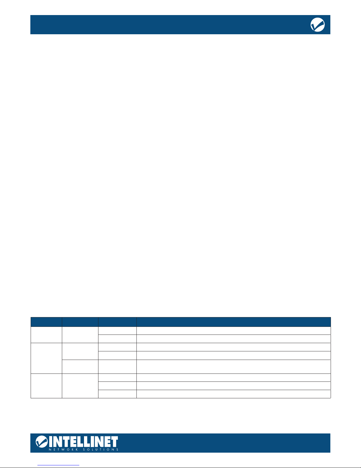
DESKTOP INSTALLATION
When installing the switch on a desktop (if not in a rack), attach the enclosed rubber feet to the bottom
corners of it to minimize vibration. Allow adequate space for ventilation between the device and the objects
around it.
Desktop Installation
7
24-Port Gigabit Ethernet PoE+ Web-Managed Switch with
4 Gigabit Combo Base-T/SFP Ports
User Manual
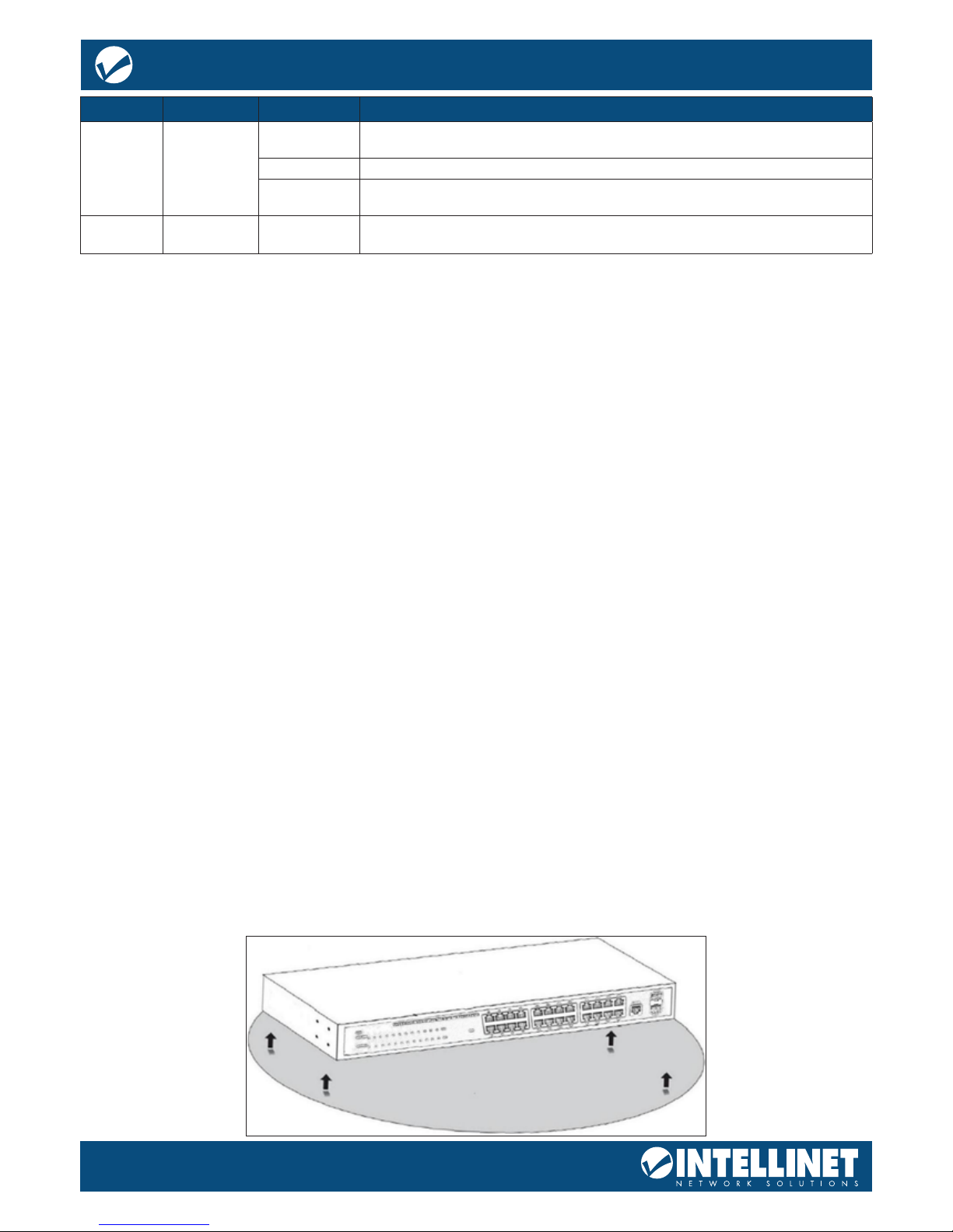
RACKMOUNT INSTALLATION IN 19” CABINET
The switch can be mounted in an EIA standard-sized, 19-inch rack, which can be placed in a wiring closet
with other equipment. To install the switch, follow these steps:
Attach the mounting brackets on the switch’s side panels (one on each side) and secure them with the
screws provided.
Use the screws provided with the equipment rack to mount the switch on the rack and tighten it.
POWER ON THE SWITCH
The switch is powered on by connecting it to an outlet using the AC 100-240V 50/60Hz internal highperformance power supply.
AC Electrical Outlet:
It is recommended to use a single-phase, three-wire receptacle with a neutral outlet or multifunctional
professional receptacle. Be sure to connect the metal ground connector to the grounding source on the
outlet.
AC Power Cord Connection:
Connect the AC power connector on the back panel of the switch to an external receptacle with the included
power cord, and then check that the power indicator is ON. When it is ON, the corresponding LED
is illuminated.
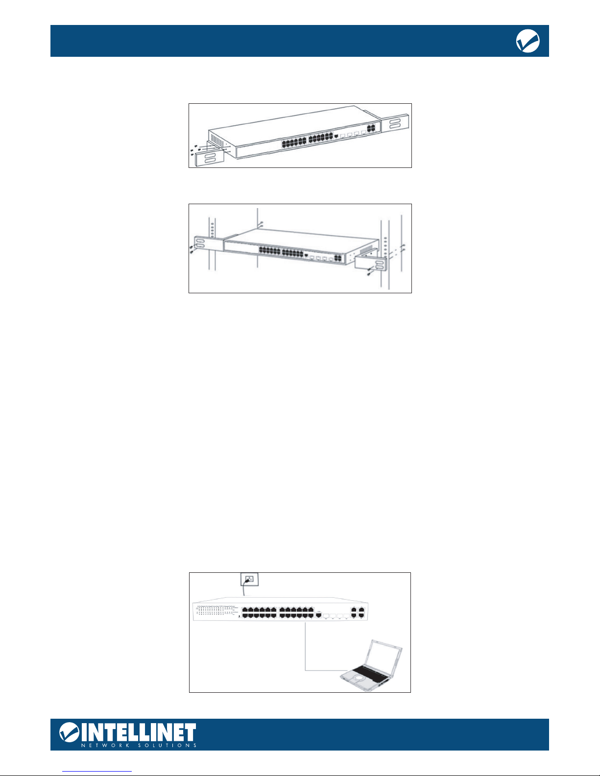
CONNECTION TO THE SWITCH
CONNECTING TO COMPUTER
Use standard Cat5e/6 Ethernet cables (UTP/STP) to connect the switch to end nodes as described below.
Switch ports will automatically adjust to the characteristics (MDI/MDI-X, speed, duplex) of the device to
which they are connected.
The LNK/ACT/Speed LEDs for each port are illuminated when the link is available.
!
8
24-Port Gigabit Ethernet PoE+ Web-Managed Switch with
4 Gigabit Combo Base-T/SFP Ports
User Manual
HOW TO LOG IN TO THE SWITCH
As the switch provides Web-based management login, congure your computer’s IP address manually to log
on to the switch. The default settings of the switch are shown below.
Parameter Default Value
Default IP address 192.168.2.1
Default Username admin
Default Password 1234
Log on to the conguration window of the switch through following steps:
1. Connect the switch with the computer NIC interface.
2. Power on the switch.
3. Check whether the IP address of the computer is within this network segment: 192.168.2.xxx (“xxx”
range is 2-254); for example, 192.168.2.100.
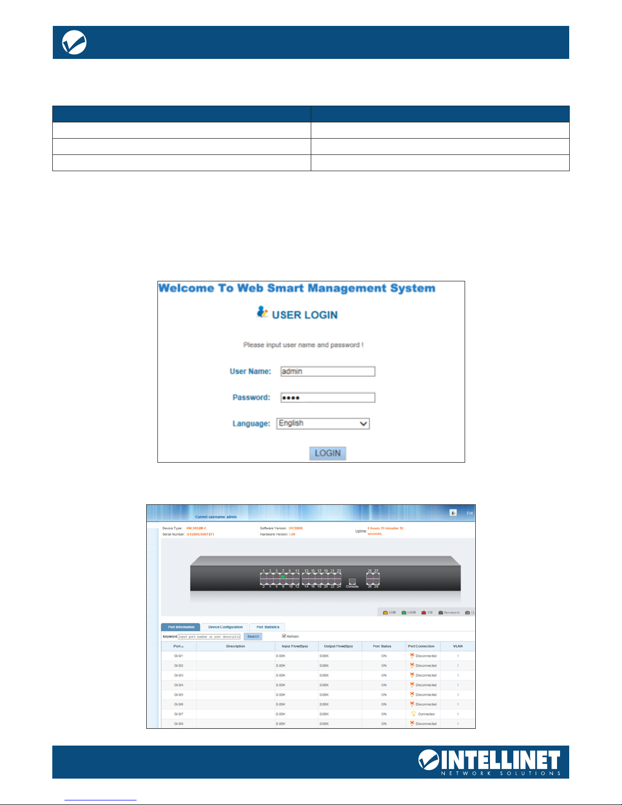
Open the browser, and go to the URL http://192.168.2.1 to access the switch login window, as shown below.
Enter the Username and Password (the factory default Username is admin and the Password is 1234), and
then click “LOGIN” to log in to the switch conguration window as below.

9
24-Port Gigabit Ethernet PoE+ Web-Managed Switch with
4 Gigabit Combo Base-T/SFP Ports
User Manual
SAVING THE CONFIGURATION
The Intellinet Network Solutions 24‐Port Gigabit Ethernet PoE+ Web Managed Switch provides a myriad of
conguration options, many of which are designed for experienced network administrators and aren’t easy
to congure. It would be a real shame if all the conguration data was lost after a power failure or after the
switch was restarted. In order to make the conguration permanent, it needs to be saved. Here is how:
SWITCH CONFIGURATION
This chapter describes how to use the web‐based management interface (Web UI) for this switch.
HOME
PORT CONFIGURATION
A green square indicates the port link is up at Gigabit speeds. A red square indicates that a PoE device is
connected. A gray square indicates the port link is down.
PORT INFORMATION, EQUIPMENT CONFIGURATION AND PORT STATISTICS
This section provides real‐time information about the ports, basic settings and trac statistics.
Item Description
Port Information
Displays the port number. The nomenclature is as follows:
Gi = Gigabit Ethernet
0/ = Switch 0 (which means this device)
1 – 24 = Port number. Ports 25 through 28 are SFP module slots
Description Optional description for the port, as entered in the basic port conguration
Input Flow (bps) Inbound trac rate, measured in “bits per second”
Output Flow (bps) Outbound trac rate, measured in “bits per second”
Open State
ON = Port is activated in the basic port conguration and will accept
connections from networking devices
OFF = Port is deactivated in basic port conguration
Status
Connect: A networking device is connected to the port and has an active link
Disconnect: No device is connected to the port
VLAN If the port belongs to a VLAN, its ID is displayed here; ID 1 = default.
Trunk Port
Yes = The port is part of an LACP trunking group
No = The port is not part of an LACP trunking group
This tab displays information about various functions and provides a short‐cut that allows direct
conguration of that part of the switch settings.

10
24-Port Gigabit Ethernet PoE+ Web-Managed Switch with
4 Gigabit Combo Base-T/SFP Ports
User Manual
QUICK SETUP
This switch provides a setting that oers direct access to some of the core functions of the device, namely
VLAN, trunking, device IP address and admin password. Even though the function is called “Quickly Set,”
there is no need to rush. Take as much time as you like with the conguration. Refer to subsequent sections
in this user guide for additional information about the individual functions.
PORT SETTINGS
BASIC CONFIG
Item Description
VLAN ID VLAN number
VLAN Name VLAN mark
Management IP Manage the IP address of the VLAN
Device Name Switch name
Management VLAN Switch’s management in use of the VLAN

11
24-Port Gigabit Ethernet PoE+ Web-Managed Switch with
4 Gigabit Combo Base-T/SFP Ports
User Manual
Item Description
Port description
Optional description for the port. A maximum of 80 characters can be provided. No special
characters or spaces are allowed.
Port speed
10M: Forces a connection to be made at 10 Mbps.
100M: Forces a connection to be made at 100 Mbps.
1000M: Forces a connection to be made at 1000 Mbps.
Auto: The switch and connected device negotiate the best possible connection speed.
Flow control
IEEE 802.3x ow control is the process of managing the rate of data transmission between
two nodes (i.e., the switch and a connected network client) to prevent a fast sender from
overwhelming a slow receiver. It provides a mechanism for the receiver to control the
transmission speed, so that the receiving node is not overwhelmed with data from the
transmitting node. That sounds like it is a good thing, and it is. So why is the option by default
set to “disabled”? The short answer is because you normally don’t need it and because it can,
in very rare instances, have a negative impact on the overall performance in your network. The
TCP protocol already provides its own ow control mechanism, allowing a sender to throttle
back the speed if the receiver is having problems keeping up.
Port status
ON: Activates the port.
OFF: Disables the port. No connections to it can be made.
Working mode
This parameter controls the duplex mode. In a full-duplex system, both parties can
communicate to the other simultaneously. An example of a full-duplex device is a telephone;
the parties at both ends of a call can speak and be heard by the other party simultaneously.
In networking terms, full duplex allows receiving and transmitting of data at the same time,
whereas half duplex does not. If the telephone is an example for full duplex, then a push-totalk CB radio or “walkie-talkie” represents half duplex. The switch can either receive or send
data, but it can never happen simultaneously. Unless you have a specic reason not to do so,
this should be left in “Auto” mode.
Cross line order
Auto MDI-X automatically detects the required cable-connection type and congures the
connection appropriately, removing the need for crossover cables to interconnect switches
or for connecting PCs peer-to-peer. As long as it is enabled on either end of a link, either type
of cable can be used. For auto MDI-X to operate correctly, the data rate on the interface and
duplex setting must be set to “auto.” When two auto MDI-X ports are connected together, which
is normal for modern products, the algorithm resolution time is typically < 500 ms. However, a
~1.4 second asynchronous timer is used to resolve the extremely rare case (with a probability
of less than 1 in 5×10²¹) of a loop where each end keeps switching. If you don’t understand
any of this, simply leave this value on “Auto.”
Access the parameters related to each of the 24 ports. The screen is divided into two sections. The upper
section displays an image of the 24 ports of the Intellinet Network Solutions switch. In order to make
changes to a port, simply click to select it.
Create a selection of multiple ports at once:
12
24-Port Gigabit Ethernet PoE+ Web-Managed Switch with
4 Gigabit Combo Base-T/SFP Ports
User Manual
Once one port or multiple ports are selected, make changes to the port settings.
The screen also shows a table that lists all 24 ports along with their parameters. The “mega frame” value
refers to jumbo frames, which are Ethernet frames with more than 1500 bytes of payload Dene the size of
the jumbo frames in the section SYSTEM -> SYSTEM CONFIG.
Clicking the pencil allows editing the port settings, exactly the same way as directly selecting the
port(s) as shown on the previous page.
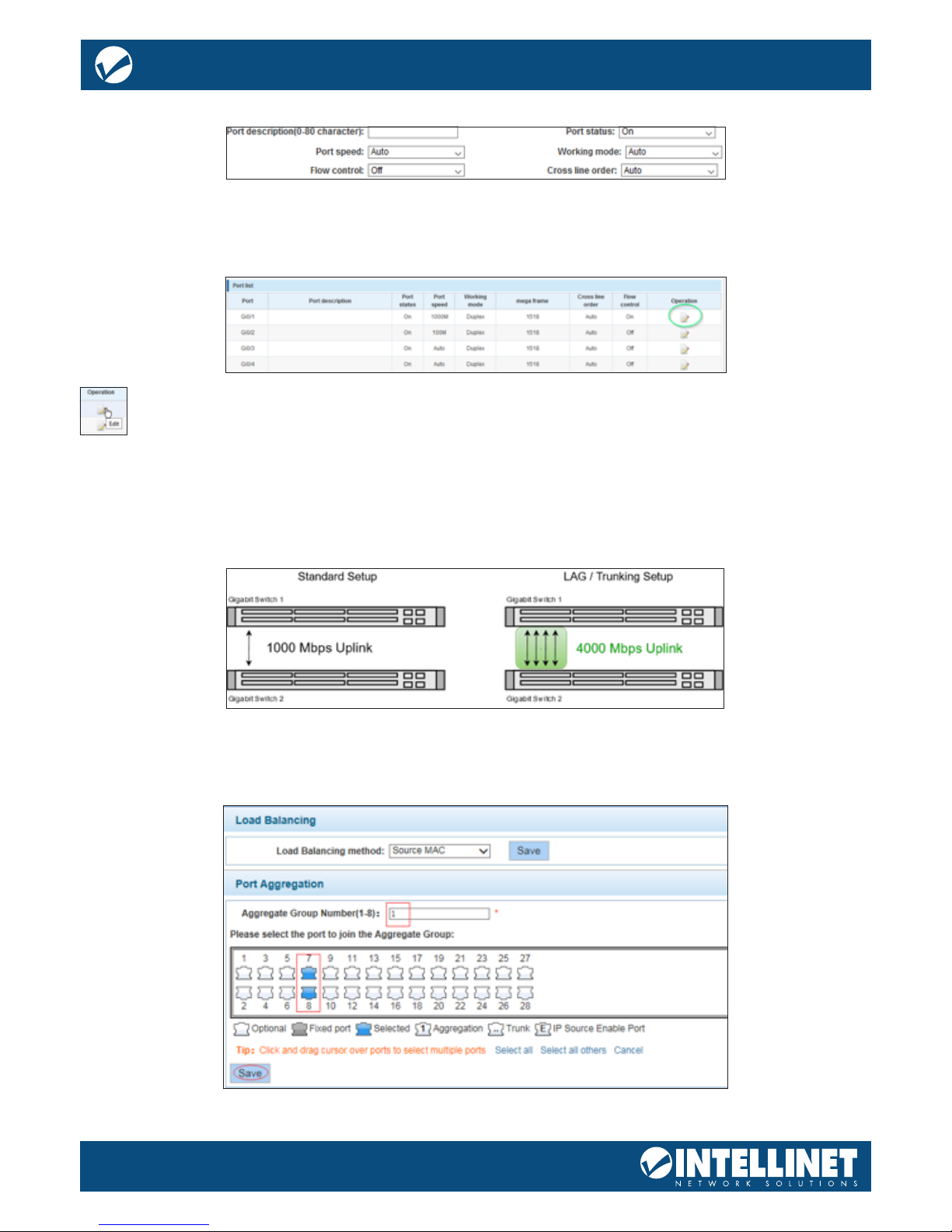
PORT AGGREGATION
Port aggregation is a method of using multiple Ethernet ports in parallel to increase throughput beyond
what a single connection could sustain and to provide redundancy in case one of the links should fail. As this
is essentially a grouping of ports into one logical unit, we call them Link Aggregation Groups, or “LAG”
for short.
This page is used to set up LAGs. Create up to eight dierent LAGs; each can have up to eight member ports.
Each LAG can be given a custom name, and you must select the ports for the LAG. The example below shows
an LAG group set up with two member ports.
13
24-Port Gigabit Ethernet PoE+ Web-Managed Switch with
4 Gigabit Combo Base-T/SFP Ports
User Manual
Item Description
Aggregate port number This is the link aggregation group (LAG) number
Select the port to join the aggregate port Select the member ports that belong to this LAG
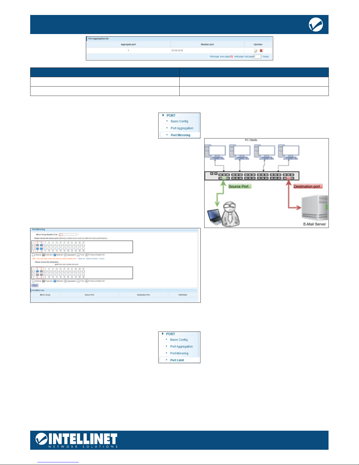
PORT MIRRORING
Port mirroring is the ability of a network switch to send a
copy of network packets seen on a switch port or ports to a
network-monitoring device connected to another switch port
(i.e., a computer equipped with a packet snier utility). The
switch provides up to four groups for port-mirroring settings.
The example below shows setting up one mirror group where
all trac occurring on ports 4, 5 and 6 is being mirrored to
port 3.
PORT SPEED LIMIT
This feature allows you to limit the data rates for a particular port on the Intellinet Network Solutions switch.
When the data rate exceeds user-congured values, the switch drops packets immediately. Rate limiting is
congured for two types of transmissions, which are ingress and egress. Ingress trac is received on any
given port (incoming, inbound, download or input speed), whereas egress trac is trac sent out (outgoing,
outbound, upload or output speed) to another network client.
14
24-Port Gigabit Ethernet PoE+ Web-Managed Switch with
4 Gigabit Combo Base-T/SFP Ports
User Manual
The switch allows controlling the available bandwidth for each port individually. The speed is measured in
kbps, which stands for kilobits per second. The default is 1 million, which is the equivalent of 1 Gigabit per
second. Values entered must be multiples of “16” (e.g., 16, 32, 48, …, 512, …., 1024, etc.).
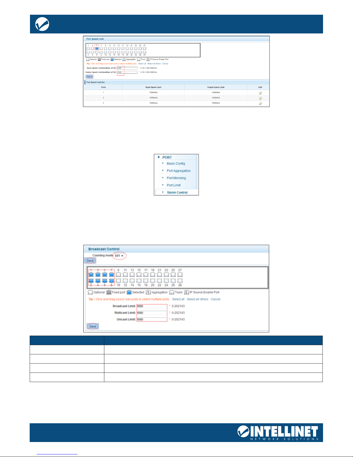
BROADCAST STORM
Storm Control prevents LAN interfaces from being disrupted by a broadcast storm. A broadcast storm occurs
when broadcast packets ood the subnet, creating excessive trac and degrading network performance.
Errors in the protocol-stack implementation or in the network conguration can cause a broadcast storm.
The Intellinet Network Solutions switch allows conguring maximum allowed pps rates for three dierent
types of packets. It’s possible to set all 24 ports to the same value or provide individual values.
Item Description
Port number 1 - 24v Select individual ports or a range of ports.
Broadcast limit Enter the maximum pps (packets per second) for broadcast packets.
Multicast limit Enter the maximum pps (packets per second) for multicast packets.
Unicast limit Enter the maximum pps (packets per second) for unicast packets.
15
24-Port Gigabit Ethernet PoE+ Web-Managed Switch with
4 Gigabit Combo Base-T/SFP Ports
User Manual
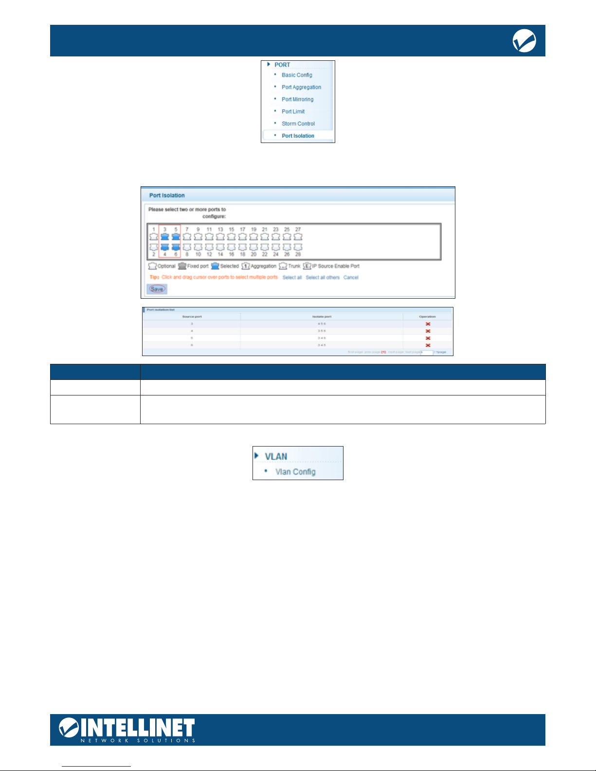
PORT ISOLATION
The port isolation function allows you to congure your Intellinet Network Solutions switch to prevent PCs
on dierent ports from communicating with each other without conguring a VLAN.
Item Description
Source Port Select the port you wish to isolate.
Isolation Port Select the port(s) to which packets from the source port can be forwarded. More than
one port can be selected here.
VLAN
A virtual LAN (VLAN) is any broadcast domain that is partitioned and isolated in a computer network at
the datalink layer (OSI layer 2). VLANs are datalink layer (OSI layer 2) constructs, analogous to IP subnets,
which are network-layer (OSI layer 3) constructs. VLANs can be used to partition a local network into several
distinctive segments.
VLAN technology provides the following advantages:
1. Broadcast trac does not cross into dierent VLANs, which reduces bandwidth utilization and
improves network performance.
2. Security in your LAN can be improved, since packets in dierent VLANs cannot communicate with each
other directly.
3. With VLAN, clients can be allocated to dierent working groups, and users from the same group do not
have to be within the same physical area, which makes network maintenance much easier and more
exible.
VLAN technology knows three types of ports — access, trunk and hybrid ports.
1. Access Ports (untagged)
a. Access ports are designed to tag any incoming packet with the VLAN ID the port has been
assigned to.
16
24-Port Gigabit Ethernet PoE+ Web-Managed Switch with
4 Gigabit Combo Base-T/SFP Ports
User Manual
b. Tagged VLAN packets arriving at the access port are dropped by the switch.
c. As far as the switch is concerned, any port that isn’t dened as a trunk or hybrid port is considered
an access port.
2. Trunk Ports (tagged)
a. Trunk ports are designed to lter out packets that have either no VLAN tag or VLAN tags that are
not on the allowed VLAN ID list.
b. Trunk ports do not remove any existing VLAN tags from incoming packets.
c. Trunk ports do not add a VLAN tag to any incoming untagged packet.
d. Trunk ports are ideal for switch-to-switch connections or for devices that have the ability to tag
packets by themselves such as VoIP phones.
3. Hybrid Ports
a. These are a combination of access and trunk ports.
b. Hybrid ports will tag any incoming packet that has no VLAN ID with the VLAN ID the port has been
assigned to.
c. Hybrid ports will also act as trunk ports for packets that have a VLAN tag.
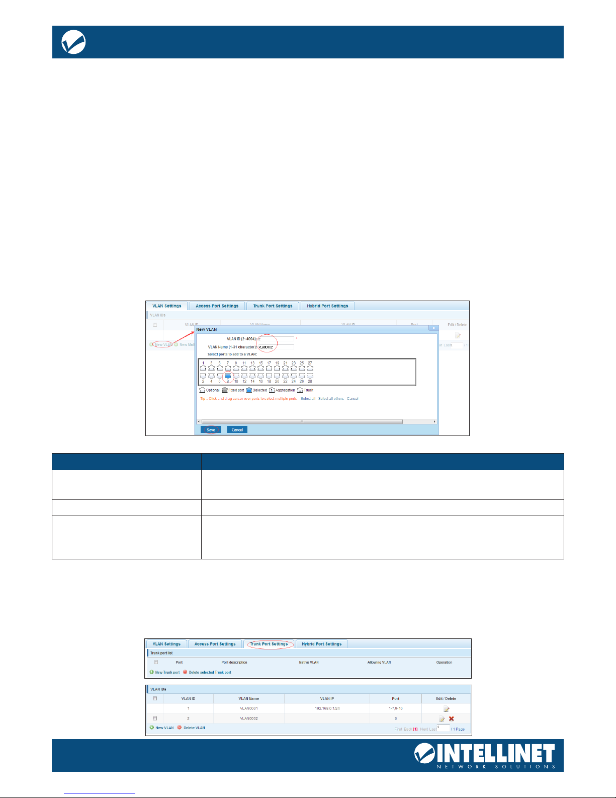
NEW VLAN
Item Description
VLAN ID Type in the ID for the new VLAN. This value cannot be “1” nor any ID already
setup on the switch.
VLAN Name Provide a descriptive name for the VLAN (e.g., “VOICE”).
Choose to join the VLAN port Select all the ports you wish to be a part of this VLAN. Note that these ports
will act as access ports. They will add the VLAN ID to any untagged packet
and reject any incoming packets that have a VLAN tag.
Note: VLAN ID 1 is the default VLAN, which cannot be removed. However, access ports that are assigned to
another VLAN will be automatically removed from VLAN 1. The screen shot below shows what the setup
looks like after the above VLAN has been added:
TRUNK PORT SETTINGS
A trunk port transmits tagged packets and is used to connect dierent switches with one another.
17
24-Port Gigabit Ethernet PoE+ Web-Managed Switch with
4 Gigabit Combo Base-T/SFP Ports
User Manual
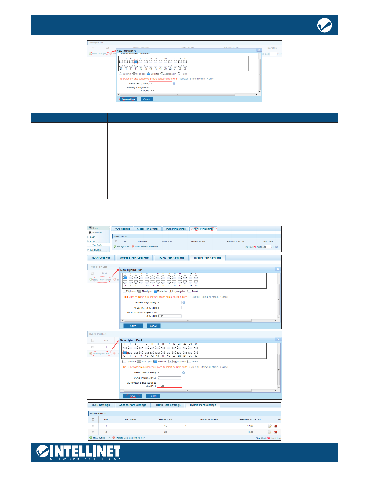
Item Description
Native VLAN ID The native VLAN ID is the untagged VLAN on an IEEE 802.1q trunked port. The
native VLAN and management VLAN (see SYSTEM->SYSTEM CONFIG) can be the
same, but in terms of security, it is better that they are not. If a switch receives
an untagged frame on a trunk port, it is assumed to be part of the Native VLAN
that is designated on the switch trunk port.
Allowing VLAN Enter the IDs of all VLANs that you wish the trunk port to forward. All other
tagged packets will be dropped.
Note that any value you enter here must rst be dened as a VLAN in the
previous VLAN settings page.
HYBRID PORT SETTINGS
A Hybrid port is a combination of a trunk and an access port.
18
24-Port Gigabit Ethernet PoE+ Web-Managed Switch with
4 Gigabit Combo Base-T/SFP Ports
User Manual
Item Description
Native VLAN ID See previous trunk port section.
VLAN TAG VLAN ID that is added to any untagged packet arriving at the port. Note: Though the
web interface may say otherwise, you cannot enter multiple IDs or ranges of IDs.
Allowed VLAN IDS Enter the IDs of all VLANs that you wish the hybrid port to forward. All other tagged
packets will be dropped.
Port Description The name of the port as dened in HOME section of this manual
Add TAG VLAN VLAN ID that is added to untagged VLAN packets.
Allowed TAG VLAN Tagged VLAN packets that are allowed to pass through, all other tagged packets will
be dropped.
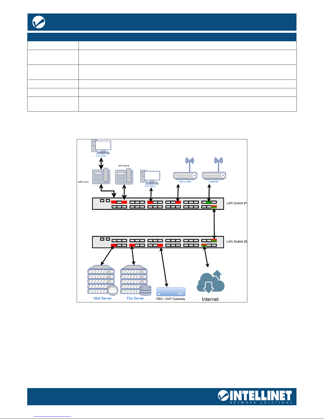
Setup Example
This section provides a real-life example and the corresponding setup of the Intellinet Network Solutions
switch, or in this case, switches.
• There are three VLANs in the network
• VLAN ID 100 – Internal data network with access to Internet
• VLAN ID 200 – VoIP network
• VLAN ID 300 – Guest network provides Internet access, but nothing else
• LAN Switch #1:
• Port 2: VoIP phone using VLAN ID 200, PC connected to back of phone
• Port 6: VoIP phone using VLAN ID 200
• Port 8: PC
• Port 10: Wireless access point for internal network and access to Internet
• Port 12: Guest wireless access point provides Internet access only
• Port 16: Connection to LAN switch #2
 Loading...