

Page 1
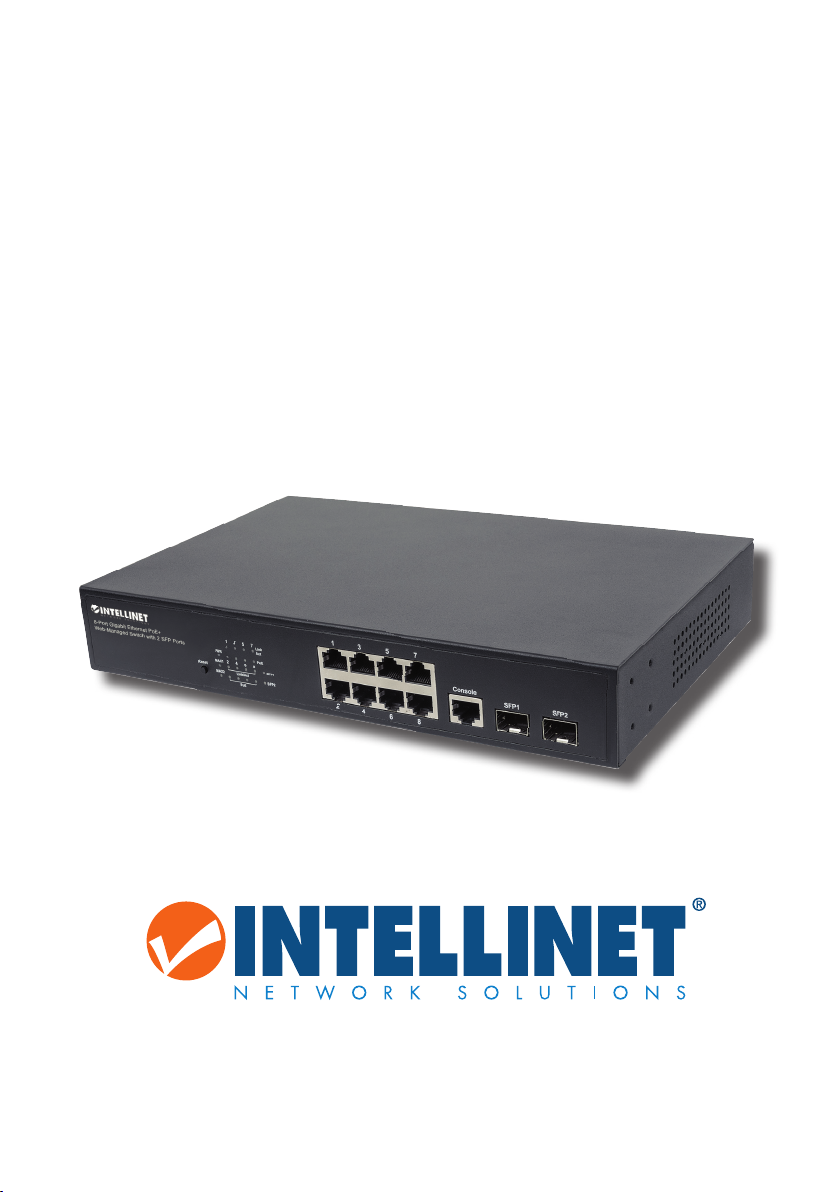
8-PORT GIGABIT
ETHERNET PoE
+
WEB-MANAGED
S
WITCH
WITH 2 SFP PORTS
QUICK INSTALL GUIDE
MODEL 561051
intellinetnetwork.com
Important: Read before use. • Importante: Leer antes de usar.
INT-561051-QIG-ML1-0815-01
Page 2
Gigabit Ethernet PoE+ Web-Managed Switch • Quick Install Guide English
This guide presents the basic steps to set up and operate this device. For detailed
instructions and specifications, refer to the user manual enclosed with this product or
at intellinetnetwork.com.
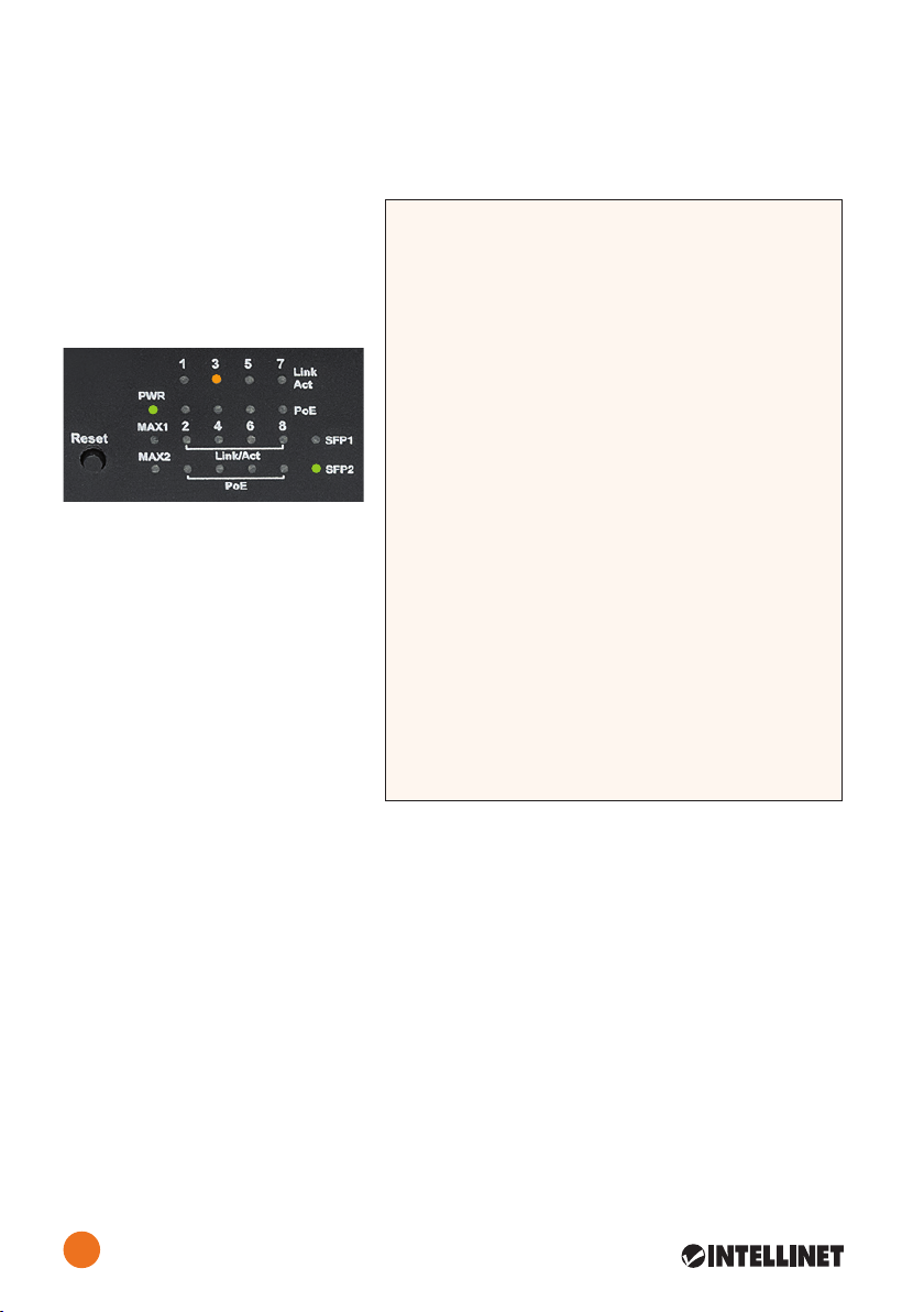
Connections & Indicators
LEDs
• Link/Act LEDs:
Orange = 10/100 Mbps
Green = 1000 Mbps
• MAX1 = Ports 1-4
MAX2 = Ports 5-8
Ports
All ports on the switch support
Auto-MDI/MDI-X functionality, so
crossover cables and uplink ports
are not needed for connections to
PCs, routers, other switches, etc.
Cat5/5e/6 UTP/STP cables provide
optimal performance; if a status LED
doesn’t indicate a link or activity,
check the corresponding device
for proper setup and operation.
Power
LED Status Operation
PWR On Power on
O Check the AC connection; turn the
power on
PoE On Port is linked to a PSE/PoE device
Blinking The PoE circuit may have a short or
overload
O No PSE/PoE device is linked; or no
power is supplied due to power limits
of the port
Link/ On Valid port connection
Act/ Blinking Valid port connection; data is being
SFP1/2 transmitted/received
Off No link established
MAX1 On The combined power output of Ports
1-4 is 55W
Blinking The combined power output of Ports
1-4 has exceeded the 70W maximum
O The combined power output of Ports
1-4 is below 55W
MAX2 On The combined power output of Ports
5-8 is 55W
Blinking The combined power output of Ports
5-8 has exceeded the 70W maximum
O The combined power output of Ports
5-8 is below 55W
Use the included power cord to connect the device (on the rear panel) to an AC outlet.
Conrm that the power LED on the front panel is lit.
Reset
Press the Reset button for 2 seconds and the switch automatically reboots. Press the
Reset button for 5 seconds to restore default settings.
Installation
(Go to Page 8)
Basic Web-Based Browser Management
1. Open your Web browser.
2. Enter “http://” and the IP address of the switch in the Address eld. The default
management IP address is 192.168.2.1.
3. Press <Enter> to display the login screen. In the Username eld, enter “admin”;
in the Password eld, enter “admin.” Click LOGIN.
2
ENGLISH
Page 3
Desktop Gigabit Web-Managed PoE+ Switch • Kurzanleitung Deutsch
Diese Kurzanleitung zeigt die grundlegenden Schritte zur Einrichtung und Inbetriebnahme dieses Geräts. Für genauere Anweisungen nutzen Sie bitte das beiliegende
Handbuch oder auf intellinetnetwork.com.
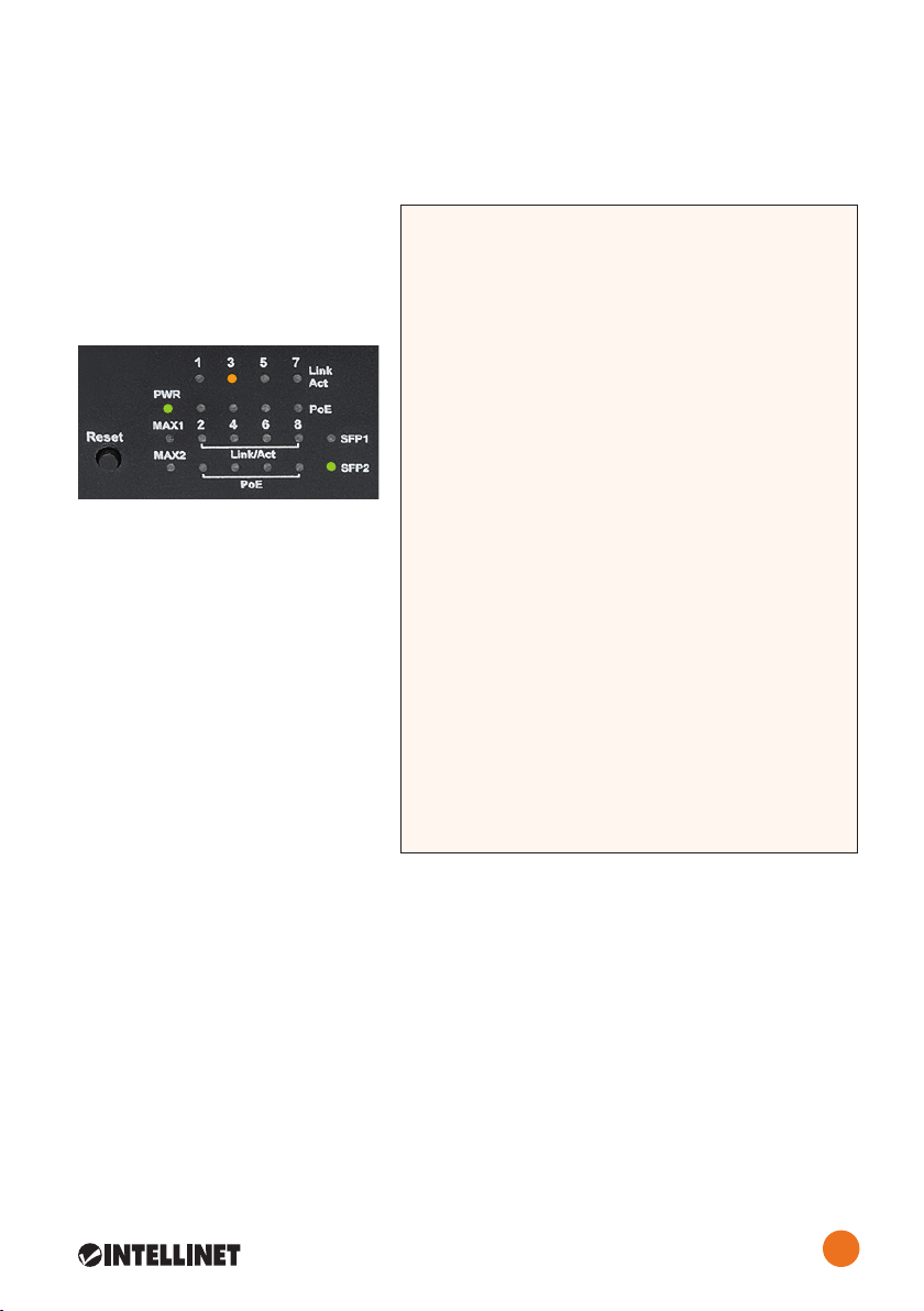
Anschlüsse & Anzeigen
LED-Anzeigen
• Link/Act LEDs:
Orange = 10/100 Mbps
Grün = 1000 Mbps
• MAX1 = Ports 1-4
MAX2 = Ports 5-8
Ports
Alle Ports unterstützen Auto-MDI/
MDI-X Funktionalität, daher werden
Crosskabel und Uplink-Ports für
Verbindungen zu PCs, Routern,
anderen Switchen, etc. nicht
benötigt. Cat5/5e- UTP/STP-Kabel
bieten die beste Performance.
Wenn eine LED keine Verbindung/
Aktivität anzeigt, überprüfen Sie
das verbundene Gerät.
Strom
Schließen Sie das beiliegende
Stromkabel an das Gerät und an
eine Steckdose an. Vergewisser Sie sich dass die “Power”-LED aueuchtet.
Reset
Halten Sie den Reset-Knopf 2 sekunden und der Switch startet automatisch neu.
Halten Sie den Reset-Knopf 5 sekunden um den Switch auf die Werkseinstellungen
zurück-zusetzen.
Installation
(Finden Sie unter Seite 8)
LED Status Operation
PWR An Gerät wird mit Strom versorgt
Auf Stromanschluss prüfen/Gerät
einschalten
PoE An Port ist mit PSE/PoE-Gerät verbunden
Auf
Aufgrund der Strombegrenzung des
Ports ndet keine Stromversorgung statt
Link/ On Verbindung ist hergestellt
Act/
SFP1/2 Datenübertragung
Auf Verbindung ist nicht hergestellt
MAX1 An Die kombinierte Ausgangsleistung der
Ports 1-4 liegt 55W
Ports 1-4 hat die maximale PoE Kapazität von 70W überschritten
Auf Die kombinierte Ausgangsleistung der
Ports 1-4 liegt unter 55W
MAX2 An Die kombinierte Ausgangsleistung der
Ports 5-8 liegt 55W
Ports 5-8 hat die maximale PoE Kapazität von 70W überschritten
Auf Die kombinierte Ausgangsleistung der
Ports 5-8 liegt unter 55W
Blinkend
Der PoE-Schaltkreis könnte einen
Kurzschluss haben oder überlastet sein
Kein PSE/PoE-Gerät angeschlossen; oder
Blinkend
Verbindung ist hergestellt;
Blinkend
Die kombinierte Ausgangsleistung der
Blinkend
Die kombinierte Ausgangsleistung der
Grundlagen der Steuerung über den Webbrowser
1. Önen Sie Ihren Webbrowser.
2. Geben Sie “http://” und die IP-Adresse des Switches in der Adresszeile ein. Die
Standard-IP-Adresse lautet 192.168.2.1.
3. Drücken Sie <Enter>, um zum Loginfenster zu gelangen. Geben Sie als
Benutzernamen “admin” und als Passwort “admin” ein. Klicken Sie auf LOGIN.
3
DEUTSCH
Page 4
Switch administrable PoE+ Gigabit Ethernet • Guía de Instalación Rápida Español
Esta guía presenta los pasos básicos para instalar y operar este dispositivo. Para obtener
instrucciones detalladas y más especicaciones, consulte el manual de usuario incluido
o en intellinetnetwork.com.
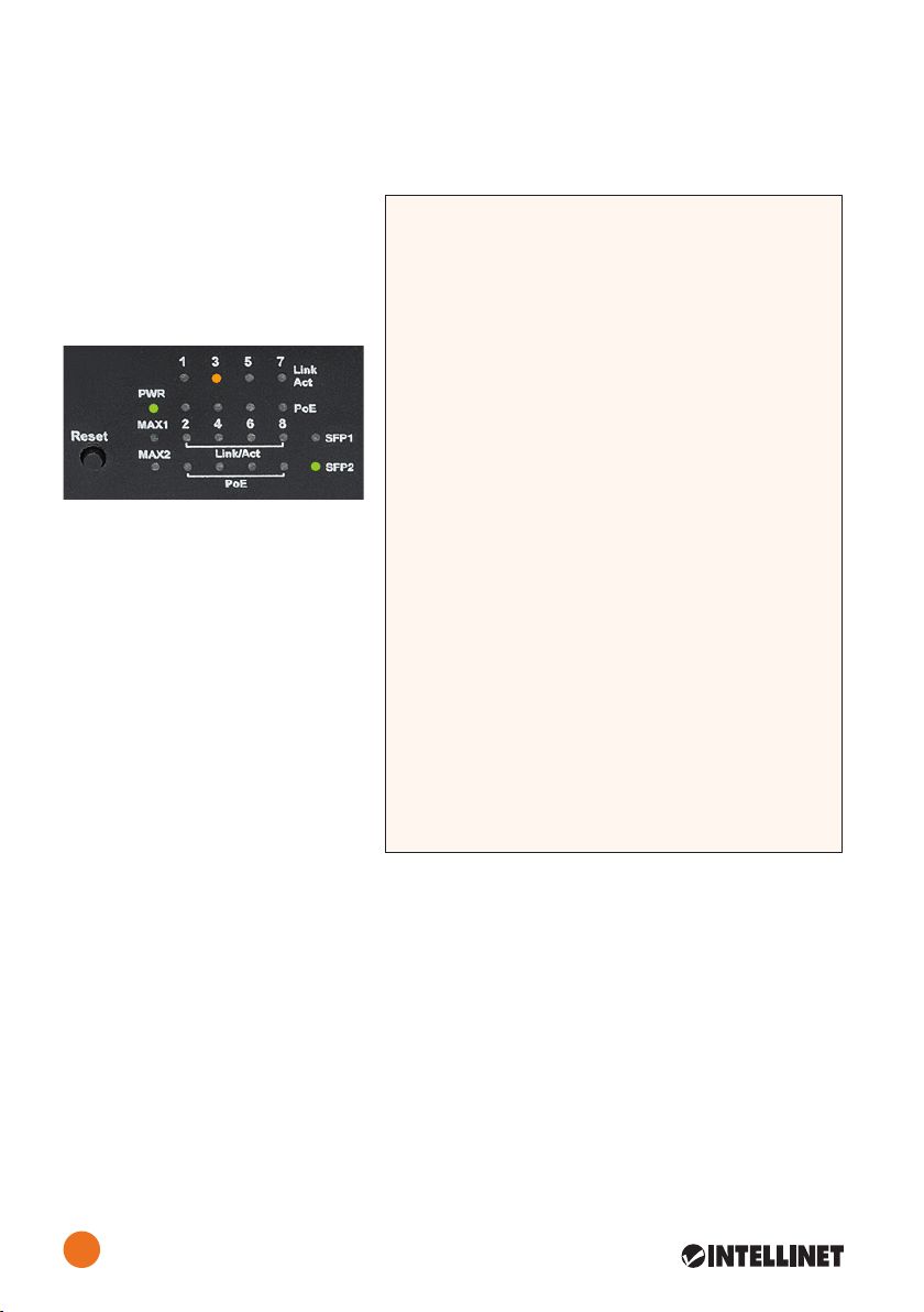
Conexiones e Indicadores
LEDs
• Link/Act LEDs:
Naranja = 10/100 Mbps
Verde = 1000 Mbps
• MAX1 = Ports 1-4
MAX2 = Ports 5-8
Puertos
Todos los puertos del switch
soportan Auto-MDI/MDI-X , los
cables crossover y puertos de
enlace no son necesarios para las
conexiones para routers, otros
switches, PCs, etc. los cables Cat5/
5e UTP/STP proporcionan un
redimiento optimo; Si un LED no
indica conectividad ó actividad,
compruebe las conexiones sean
adecuadas.
Alimentación
Utilice el cable de alimentación
LED Status Operación
PWR
Apagado Revise la conexión AC; encienda de
nuevo
PoE
PoE
Parpadeo El circuito PoE puede tener un corto o
sobrecarga
Apagado No hay un dispositivo PSE/PoE
conectado; o no se suministra energía
debido a los límites de potencia del
puerto
Link/
Act/ Parpadeo Datos trasmitidos/recibidos
MAX1
1-4 está 55W PoE
Parpadeo La potencia combinada de los puertos
1-4 ha superado el rango máximo de
70W PoE
Apagado La potencia combinada de los puertos
1-4 está por debajo 55W PoE
MAX2
5-8 está 55W PoE
Parpadeo La potencia combinada de los puertos
5-8 ha superado el rango máximo de
70W PoE
Apagado La potencia combinada de los puertos
5-8 está por debajo 55W PoE
Encendido
Encendido
Encendido
SFP1/2
Apagado No hay comunicación
Encendido
Encendido
Encendido
Puerto vinculado a un dispositivo PSE/
Conexión de puerto válido
La potencia combinada de los puertos
La potencia combinada de los puertos
incluido para conectar el dispositivo a una toma de CA. Conrme que el LED en el panel
frontal está encendido.
Reset
Presione el botón “reset” por 2 segundos y el switch se reinicia automáticamente. Presione el botón “reset” por 5 segundos Para restablecer el switch a los ajustes de fábrica.
Instalación
(ir a la página 8)
Administración básica vía Navegador Web
1. Inicie su Navegador Web.
2. Ingrese “http://” y la dirección IP del switch en la barra de direcciones. La dirección de
administración por defecto es 192.168.2.1.
3.
Presione <Enter> para ingresar a la pantalla de inicio de sesión. El nombre de usuario
es “admin”, la contraseña es “admin”. Haga clic en LOGIN.
4
ESPAÑOL
Page 5

Commutateur Web PoE+ Gigabit Ethernet • Guide d’installation rapide Français
Ce guide décrit les bases pour congurer et opérer cet appareil. Pour des instructions
et spécications détailées, veuillez lire le manuel de l’utilisateur inclus ou sur
intellinetnetwork.com.
Connexions & Indicateurs
Les DELs
• Link/Act DELs:
Orange = 10/100 Mbps
Vert = 1000 Mbps
• MAX1 = Ports 1-4
MAX2 = Ports 5-8
Les Ports
Tous les ports de ce commutateur
prennent en charge la fonction-
nalité Auto-MDI/MDI-X, donc des
câbles croisés et des liaisons
montantes ne sont pas nécessaires
pour des connections aux PC,
routeurs, etc. Des câbles Cat5/5e
UTP/STP garantissent des
performances optimales; si un DEL
n’indique pas d’activité, vériez
l’appareil correspondant.
Alimentation
Connectez le cordon d’alimentation à l’appareil et à une prise de courant. Vériez que
le DEL “Power” sur le panneau avant est allumé.
Reset
Appuyez 2 secondes sur le bouton Reset et le commutateur redémarre automatiquement. Appuyez 25 secondes sur le bouton Reset pour un reset du commutateur à la
configuration d’origine.
Installation
(voir page 8)
DEL Status Operation
PWR Allumé Appareil est alimenté
Éteint
PoE Allumé
surcharge
Éteint Port n’est connecté pas à un appareil
PSE/PoE; ou pas de l’énergie est fournie
en raison de limites de puissance du
port
Link/ Allumé Connexion est établie
Act/
SFP1/2 transmises
Éteint Connexion n’est pas établie
MAX1 Allumé La puissance de sortie combinée des
ports 1-4 est 55 W
ports 1-4 est plus que le maximum de
70 W
Éteint La puissance de sortie combinée des
ports 1-4 est inférieur 55 W
MAX2 Allumé La puissance de sortie combinée des
ports 5-8 est 55 W
ports 5-8 est plus que le maximum de
70 W
Éteint La puissance de sortie combinée des
ports 5-8 est inférieur 55 W
Clignotant Le circuit PoE peut avoir un court ou de
Clignotant
Clignotant
Clignotant
Vériez l’alimentation/Allumez l’appareil
Port est connecté à un appareil PSE/PoE
Connexion est établie; données sont
La puissance de sortie combinée des
La puissance de sortie combinée des
Base de la gestion Web
1. Ouvrez votre navigateur Web.
2. Entrez “http://” et l’adresse IP du commutateur dans le champ Adresse. L’adresse IP
par défaut de gestion est 192.168.2.1.
3.
Appuyez sur <Entrée> pour acher la fenêtre connexion. Dans le champ nom utilisa-
teur, entrez “admin”; dans le champ mot de passe, entrez “admin.” Cliquez sur LOGIN.
FRANÇAIS
5
Page 6

Przełącznik Web-Smart Gigabit PoE+ • Instrukcja szybkiej instalacji Polski
Ta instrukcja prezentuje podstawowe kroki podłączenia i instalacji urządzenia. Aby
uzyskać szczegółowe informacje techniczne oraz instrukcję użytkownika zapoznaj się z
zawartością dołączoną do opakowania lub odwiedź stronę intellinetnetwork.com.
Panel Przedni Urządzenia
Diody
• Link/Act diody:
Pomarańczowy = 10/100 Mbps
Zielony = 1000 Mbps
• MAX1 = Diody 1-4
MAX2 = Diody 5-8
Porty
Wszystkie porty przełącznika
obsługują auto-krosowanie MDI/
MDI-X, więc kabel krosowany oraz
port uplink nie jest wymagany do
połączenia z komputerami, routerami, czy innymi przełącznikami.
Kable Cat5/5e/6 UTP/STP zapewniają
optymalną wydajność; jeśli diody
statusu nie sygnalizują linku lub
aktywności, sprawdź podłączone
urządzenie pod kątem poprawności
konguracji oraz jego zasilania.
Zasilanie
Dioda Status Objaśnienie
PWR On (wł.) Urządzenie włączone
O (wył.)
włącz urządzenie
PoE On (wł.) Port jest połączony z urządzeniem PoE
Migająca Obwód PoE może być przeciążony lub
ma zwarcie
O (wył.) Nie ma połączenia z urządzeniem PoE;
lub brak zasilania z powodu
ograniczenia mocy na porcie
Link/ On (wł.) Prawidłowe podłączenie portu
Act/ Migająca Prawidłowe podłączenie portu;
SFP1/2 transmisja/odbiór pakietów
O (wył.) Nie nawiązano połączenia
MAX1 On (wł.) Łączne zapotrzebowanie na moc w
portach 1-4 jest 55W
Migająca Łączne zapotrzebowanie na moc w
portach 1-4 przekroczyło maksymalny
budżet 70W mocy
O (wył.) Łączne zapotrzebowanie na moc w
portach 1-4 jest poniżej 55W
MAX2 On (wł.) Łączne zapotrzebowanie na moc w
portach 5-8 jest 55W
Migająca Łączne zapotrzebowanie na moc w
portach 5-8 przekroczyło maksymalny
budżet 70W mocy
O (wył.) Łączne zapotrzebowanie na moc w
portach 5-8 jest poniżej 55W
Sprawdź, czy zasilanie jest podłączone;
Użyj znajdującego się w zestawie kabla zasilającego do podłączenia przełącznika do
gniazda sieci energetycznej. Sprawdź, czy dioda zasilania (Power) zapaliła się.
Reset
Wciśnij i przytrzymaj przez 2 sekundy przycisk resetu i przełącznik automatycznie
zrestartuje. Wciśnij i przytrzymaj przez 5 sekundy aby przywrócić przełącznik do jego
ustawień domyślnych.
Instalacja
(Patrz strona 8)
Konguracja podstawowa
1. Otwórz przeglądarkę internetową.
2. Wpisz „http://” oraz adres IP przełącznika w pasek adresu przeglądarki. Domyślnym
adresem IP urządzenia jest 192.168.2.1.
3. Wciśnij <Enter>, aby wyświetlić okno logowania. W pole nazwa użytkownika wpisz
„admin”, w pole hasło wpisz „admin”. Wciśnij LOGIN.
6
POLSKI
Page 7

Switch Gigabit Ethernet PoE+ Web-Managed • Guida rapida all’installazione
Italiano
Questa guida fornisce le indicazioni basilari per settare e mettere in funzione
l’apparecchio. Per istruzioni dettagliate e ulteriori speciche, fare riferimento al manuale d’istruzione contenuto nel CD incluso al prodotto o sul sito intellinetnetwork.com.
Connessioni e Indicatori
LEDs
• Link/Act LEDs:
Arancia = 10/100 Mbps
Verde = 1000 Mbps
• MAX1 = LED 1-4
MAX2 = LED 5-8
Porte
Tutte le porte dello switch
supportano la funzionalità AutoMDI/MDI-X, così cavi incrociati e
porte uplink non sono necessarie
per connessioni a PC, router, altri
switch, etc. I cavi Cat5/5e/6 UTP/STP
forniscono ottimali prestazioni; se
il LED di stato non indica una
connessione o un’attività, vericare
la corrispondente periferica per un
corretto settaggio e funzionamento.
Alimentazione
LED Stato Operazione
PWR Acceso Acceso
Spento Vericare la connessione AC; accendere
l’apparecchio
PoE Acceso Porta collegata alla periferica PSE/PoE
Lamp. Ci può essere un corto circuito o un
sovraccarico
Spento Nessuna periferica PSE/PoE è collegata;
o non viene fornita alimentazione a
causa dei limiti di potenza del porto
Link/ Acceso Porta di connessione valida
Act/ Lamp. Porta di connessione valida;
SFP1/2 trasmissione/ricevimento dati
Spento Nessuna connessione stabilita
MAX1 Acceso La potenza combinata delle porte 1-4
ha raggiunto 55W
Lamp. La potenza combinata delle porte 1-4
ha superato il budget PoE massimo di
70W
Spento La potenza combinata delle porte 1-4 è
inferiore 55W
MAX2 Acceso La potenza combinata delle porte 5-8
ha raggiunto 55W
Lamp. La potenza combinata delle porte 5-8
ha superato il budget PoE massimo di
70W
Spento La potenza combinata delle porte 5-8 è
inferiore 55W
Utilizzare il cavo di alimentazione per collegare l’apparecchiatura (sul pannello posteriore)
alla presa di corrente AC. Vericare che il LED di alimentazione sul pannello frontale è
illuminato.
Reset
Premere il tasto Reset per 2 secondi e lo switch automaticamente si riavvia. Premere il
tasto Reset per 5 secondi per resettare lo switch alle impostazioni di fabbrica.
Installazione
(Vedere a pagina 8)
Gestione tramite browser
1. Aprire il vostro Web browser.
2.
Inserire “http://” e l’indirizzo IP dello switch nel campo riservato all’indirizzo. L’indirizzo
IP predenito è 192.168.2.1.
Premere <Invio> per visualizzare la schermata di accesso. Nel campo Username,
3.
inserire “admin”; nel campo Password, inserire “admin.” Cliccare LOGIN.
ITALIANO
7
Page 8

Rackmount Installation
2 & 3
4
The switch includes brackets and screws for optional rack mounting:
1. Disconnect any cables from the switch.
2. Position a bracket over the mounting holes on one side of the switch and secure it in
place with screws.
3. Repeat Step 2 on the other side of the switch.
4. Position the switch in the rack and screw the brackets to the rack.
5. Reconnect any cables.
Prior to use, it is recommended that the switch be placed/positioned on a level surface
with at least 25 mm (approx. 1”) of clearance for ventilation; away from sources of electrical noise: radios, transmitters, broadband ampliers, etc.; and within 100 m (approx.
328’) of network devices it’s to be connected to.
Deutsch
Diesem Switch liegen Haltewinkel und Schrauben für optionale Rackmontage bei:
1. Trennen Sie alle Kabel von dem Switch.
2. Platzieren Sie einen Haltewinkel über den Montagelöchern auf einer Seite des
Switches und xieren Sie ihn mit Schrauben.
3. Wiederholen Sie Schritt 2 auf der anderen Seite des Switches.
4. Platzieren Sie den Switch in dem Rack und schrauben Sie die Haltewinkel fest.
5. Schließen Sie alle Kabel wieder an.
Es wird empfohlen, den Switch vor der Nutzung folgendermaßen aufzustellen auf eb-
enem Untergrund mit mind. 25 mm Rundumabstand für ausreichend Luftdurchsatz;
fern von anderen Übertragungsgeräten wie Radio, Breitbandverstärker, etc.; und max.
100 m vom zu verbindenden Netzwerkgerät entfernt.
8
INSTALLATION
Page 9

Español
El switch incluye soportes y tornillos opcionales para el montaje en el Rack:
1. Desconecte cualquier cable del switch.
2. Coloque el soporte sobre los oricios de montaje, ubicados a un lado del switch y sujételo
con los tornillos.
3. Repita el paso 2 en el lado contrario del switch.
4. Coloque el switch en el rack y atornille los soportes al rack.
5. Conecte nuevamente todos los cables.
Antes de utilizarlo, se recomienda que el switch sea ubicado/jado sobre una supercie plana
con al menos 25 mm de espacio libre para ventilación; lejos de fuentes de ruido: radios, transmisores, amplicadores de banda ancha, etc.; y dentro de los 100 m (aprox. 328’) deben estar
conectados los dispositivos de red.
Français
Le commutateur inclut des équerres et vis pour un montage en rack optionnelle ::
1. Déconnectez tous les cordons du
commutateur.
2. Positionnez une équerre sur les trous de
montage à un côté du commutateur et
sécurisez-la avec des vis.
3. Répétez l’étape 2 à l’autre côté du
commutateur.
4. Positionnez le commutateur en rack et
vissez les équerres au rack.
5. Reconnectez tous les cordons.
Avant d’utiliser le commutateur, il est
recommandé de le placer sur une surface
plane avec un écartement de 25 mm
d’autres objets pour la ventilation; loin des
appareils électriques qui peuvent être source
d‘interférence (des radios etc.); et pas plus
loin que 100 m de l’appareil réseau auquel
vous voudriez connecter.
Polski
W zestawie znajdują się uchwyty oraz śrubki do opcjonalnego mocowania rackowego:
1. Odłącz wszystkie kable od przełącznika.
2. Umieść uchwyt na dziurach na bocznej części przełącznika i przykręć go śrubami.
3. Powtórz czynność z punktu nr 2 dla drugiego uchwytu.
4. Umieść przełącznik w racku i przykręć go śrubami.
5. Podłącz kable.
Zaleca się, aby urządzenie w trakcie użytkowania było umiejscowione dla zapewnienia dobrej
wentylacji w odległości co najmniej 25 mm obudowy urządzenia od podłoża, na którym się
znajduje; z dala od źródeł zakłóceń elektrycznych: radia, nadajnik, itp.; i w odległości do 100 m
od innych urządzeń sieciowych, z którymi bezpośrednio jest połączony.
Italiano
Lo switch include staffe e viti per il montaggio opzionale a rack:
1. Disconnettere qualsiasi cavo dallo switch.
2. Posizionare la staa sui fori di ssaggio su
un lato dello switch e assicurarla sul posto
con le viti.
3.
Ripetere il passo 2 sull’altro lato dello switch.
4. Posizionare lo switch sul rack ed avvitare le
staffe sul rack.
5. Recollegare i cavi.
Prima dell’uso, si raccomanda che lo switch
venga posizionato su una supercie piana
con almeno 25 mm di spazio libero per una
corrette ventilazione; lontano da fonti di
disturbo elettrico: radio, trasmettitori, ampli-
ficatori a banda larga, etc.; e entro 100 m dalle
periferiche di rete a cui è stato connesso.
INSTALLATION
9
Page 10

WARRANTY INFORMATION
English: For warranty information, go to intellinetnetwork.com/warranty.
Deutsch: Garantieinformationen nden Sie unter intellinetnetwork.com/warranty.
Español: Si desea obtener información sobre la garantía, visite intellinetnetwork.com/warranty.
Français: Pour consulter les informations sur la garantie, visitez intellinetnetwork.com/warranty.
Polski: Informacje dotyczące gwarancji znajdują się na stronie intellinetnetwork.com/warranty.
Italiano: Per informazioni sulla garanzia, accedere a intellinetnetwork.com/warranty.
En México: Póliza de Garantía Manhattan — Datos del
importador y responsable ante el consumidor IC Intracom México, S.A.P.I. de C.V. • Av. Interceptor Poniente #
73, Col. Parque Industrial La Joya, Cuautitlán Izcalli, Estado de México, C.P. 54730, México. • Tel. (55)1500-4500
La presente garantía cubre los siguientes productos
contra cualquier defecto de fabricación en sus materiales y mano de obra.
A. Garantizamos los productos de limpieza, aire com primido y consumibles, por 60 dias a partir de la
fecha de entrega, o por el tiempo en que se agote
totalmente su contenido por su propia función de
uso, lo que suceda primero.
B. Garantizamos los productos con partes móviles por
3 años.
C. Garantizamos los demás productos por 5 años (pro ductos sin partes móviles), bajo las siguientes condi ciones:
1. Todos los productos a que se reere esta garantía,
ampara su cambio físico, sin ningún cargo para el
consumidor.
2. El comercializador no tiene talleres de servicio,
debido a que los productos que se garantizan no
cuentan con reparaciones, ni refacciones, ya que
su garantía es de cambio físico.
3. La garantía cubre exclusivamente aquellas partes,
equipos o sub-ensambles que hayan sido instala das de fábrica y no incluye en ningún caso el equipo
adicional o cualesquiera que hayan sido adiciona-
dos al mismo por el usuario o distribuidor.
Para hacer efectiva esta garantía bastará con presentar
el producto al distribuidor en el domicilio donde fue ad-
quirido o en el domicilio de IC Intracom México, S.A.P.I.
de C.V., junto con los accesorios contenidos en su empaque, acompañado de su póliza debidamente llenada
y sellada por la casa vendedora (indispensable el sello y
fecha de compra) donde lo adquirió, o bien, la factura
o ticket de compra original donde se mencione clara-
mente el modelo, número de serie (cuando aplique) y
fecha de adquisición. Esta garantía no es válida en los
siguientes casos: Si el producto se hubiese utilizado en
condiciones distintas a las normales; si el producto no
ha sido operado conforme a los instructivos de uso; o si
el producto ha sido alterado o tratado de ser reparado
por el consumidor o terceras personas.
REGULATORY STATEMENTS
This equipment has been tested and found to comply with the limits for a Class B digital device, pursuant to Part
15 of Federal Communications Commission (FCC) Rules. These limits are designed to provide reasonable protection against harmful interference in a residential installation. This equipment generates, uses and can radiate
radio frequency energy, and if not installed and used in accordance with the instructions may cause harmful
interference to radio communications. However, there is no guarantee that interference will not occur in a par-
ticular installation. If this equipment does cause harmful interference to radio or television reception, which can
be determined by turning the equipment o and on, the user is encouraged to try to correct the interference
by one or more of the following measures: reorient or relocate the receiving antenna; increase the separation
between the equipment and the receiver; connect the equipment to an outlet on a circuit dierent from the
receiver; or consult the dealer or an experienced radio/TV technician.
English: This device complies with the requirements of directives 2014/53/EU and/or 2004/108/EC &
2006/95/EC. The Declaration of Conformity for this product is available at:
Deutsch: Dieses Gerät enspricht den Direktiven 2014/53/EU und/oder 2004/108/EC & 2006/95/EC. Die
Konformitätserklärung für dieses Produkt nden Sie unter:
Español: Este dispositivo cumple con los requerimientos de las Directivas 2014/53/UE y/o 2004/108/EC &
2006/95/EC. La declaración de conformidad para este producto esta disponible en:
Français: Cet appareil satisfait aux exigences des directives 2014/53/UE et/ou 2004/108/CE & 2006/95/CE.
La Déclaration de Conformité pour ce produit est disponible à l’adresset :
Polski: Urządzenie spełnia wymagania dyrektyw 2014/53/UE i/lub 2004/108/EC & 2006/95/EC. Deklaracja
zgodności dostępna jest na stronie internetowej producenta:
Italiano: Questo dispositivo è conforme alle direttive 2014/53/UE e/o 2004/108/EC & 2006/95/EC. La
dichiarazione di conformità per questo prodotto è disponibile al:
FCC Class B
CE (RE / EMC / LVD)
intellinetnetwork.com
10
Page 11

WASTE ELECTRICAL & ELECTRONIC EQUIPMENT
Disposal of Electric and Electronic Equipment per the European Union’s WEEE Directive: 2012/19/EU
English: This symbol on the product or its packaging indicates that this product shall not be treated as house-
hold waste. Instead, it should be taken to an applicable collection point for the recycling of electrical and electronic equipment. By ensuring this product is disposed of correctly, you will help prevent potential negative
consequences to the environment and human health, which could otherwise be caused by inappro priate waste handling of this product. If your equipment contains easily removable batteries or accumu lators, dispose of these separately according to your local requirements. The recycling of materials will
help to conserve natural resources. For details about recycling this product, contact your local city oce,
your household waste disposal service or the shop where you purchased this product. Outside the EU: To discard
this product, contact your local authorities and ask for the correct manner of disposal.
Deutsch: Dieses auf dem Produkt oder der Verpackung angebrachte Symbol zeigt an, dass dieses Produkt nicht
mit dem Hausmüll entsorgt werden darf. In Übereinstimmung mit der Richtlinie 2012/19/EU des Europäischen
Parlaments und des Rates über Elektro- und Elektronik-Altgeräte (WEEE) darf dieses Elektrogerät nicht im normalen Hausmüll oder dem Gelben Sack entsorgt werden. Wenn Sie dieses Produkt entsorgen möchten, bringen
Sie es bitte zur Verkaufsstelle zurück oder zum Recycling-Sammelpunkt Ihrer Gemeinde.
Español: Este símbolo en el producto o su embalaje indica que el producto no debe tratarse como residuo
doméstico. De conformidad con la Directiva 2012/19/UE de la UE sobre residuos de aparatos eléctricos y electrónicos (RAEE), este producto eléctrico no puede desecha se con el resto de residuos no clasicados. Deshágase
de este producto devolviéndolo a su punto de venta o a un punto de recolección municipal para su reciclaje.
Français: Ce symbole sur Ie produit ou son emballage signie que ce produit ne doit pas être traité comme un
déchet ménager. Conformément à la Directive 2012/19/UE sur les déchets d’équipements électriques et électroniques (DEEE), ce produit électrique ne doit en aucun cas être mis au rebut sous forme de déchet municipal non
trié. Veuillez vous débarrasser de ce produit en Ie renvoyant à son point de vente ou au point de ramassage local
dans votre municipalité, à des ns de recyclage.
Polski: Jeśli na produkcie lub jego opakowaniu umieszczono ten symbol, wówczas w czasie utylizacji nie wolno wyrzucać tego produktu wraz z odpadami komunalnymi. Zgodnie z Dyrektywą Nr 2012/19/UE w sprawie
zużytego sprzętu elektrycznego i elektronicznego (WEEE), niniejszego produktu elektrycznego nie wolno
usuwać jako nie posortowanego odpadu komunalnego. Prosimy o usuniecie niniejszego produktu poprzez
jego zwrot do punktu zakupu lub oddanie do miejscowego komunalnego punktu zbiórki odpadów przeznaczonych do recyklingu.
Italiano: Questo simbolo sui prodotto o sulla relativa confezione indica che il prodotto non va trattato come
un riuto domestico. In ottemperanza alla Direttiva UE 2012/19/UE sui riuti di apparecchiature elettriche ed
elettroniche (RAEE), questa prodotto elettrico non deve essere smaltito come riuto municipale misto. Si prega
di smaltire il prodotto riportandolo al punto vendita o al punto di raccolta municipale locale per un opportuno
riciclaggio.
North & S outh Americ a
IC Intracom Americas
550 Commerce Blvd.
Oldsmar, FL 34677
USA
© IC Intracom. All rights reserved. Manhattan is a trademark of IC Intracom, registered in the U.S. and other countries.
Asia & Afr ica
IC Intraco m Asia
4-F, No. 77, Sec. 1, Xintai 5th Rd.
Xizhi Dist ., New Taipei City 221
Taiwan
Europe
IC Intracom Europe
Löhbache r Str. 7
D-58553 Halver
Germany
11
Page 12

 Loading...