

Intellinet 560405 User Manual
16 -PORT
FAST ETHERNET
RACKMOUNT
POE SWITCH
USER MANUAL
Model 560405
INT-560405-UM-ML-0310-01
ENGLISH
DEUTSCH
ESPAÑOL
FRANÇAIS
POLSKI
ita lia no
2
ENGLISH
16-Port Fast Ethernet Rackmount PoE Switch • User Manual English
Thank you for purchasing the INTELLINET NETWORK SOLUTIONS™ 16-Port Fast Ethernet
Rackmount PoE Switch, Model 560405.
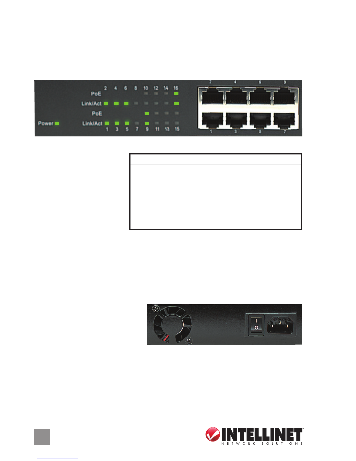
CONNECTIONS & INDICATORS
LEDs
The LED indicators — Power,
PoE, Link/Activity — make it
easier to monitor the switch
and its connections. NOTE:
Only Ports 9-16 can provide
power to a connected device;
all powered devices should
also comply with IEEE 802.3af.
Ports
All ports on the switch support Auto-MDI/MDI-X functionality, so crossover cables and
uplink ports are not needed for connections to PCs, routers, hubs, other switches, etc.
Cat5/5e/6 UTP/STP cables provide optimal performance; if a status LED doesn’t indicate
a link or activity, check the corresponding device for proper setup and operation.
Power
Use the included power cord to
connect the device (next to the
On/O switch on the rear panel)
to an AC outlet. Conrm that the
power LED on the front panel is lit.
INSTALLATION TIPS
Prior to use, it is recommended that the switch be placed/positioned:
• on a level surface with at least 25 mm (approx. 1”) of clearance for ventilation;
• away from sources of electrical noise: radios, transmitters, broadband ampliers, etc.;
• within 100 m (approx. 328’) of network devices it’s to be connected to.
LED Status Operation
Power On Power on
O Check the AC connection; turn the power on
PoE On Port is linked to a PSE/PoE device
O No PSE/PoE device is linked
Link/Act On Valid port connection
Blinking Valid port connection; data transmitted/received
O No link established
On
Off
Power
1 3 5 7 9 11 13 15
2 4 6 8 10 12 14 16
PoE
PoE
Link/Act
Link/Act
1 3 5 7
2 4 6 8
16 RJ45 10/100M ports (1-8 shown)
DEUTSCH
3
16-Port Fast Ethernet PoE Switch • Handbuch Deutsch
Vielen Dank für den Kauf des INTELLINET NETWORK SOLUTIONS™ 16-Port Fast Ethernet
PoE Switch, Modell 560405.
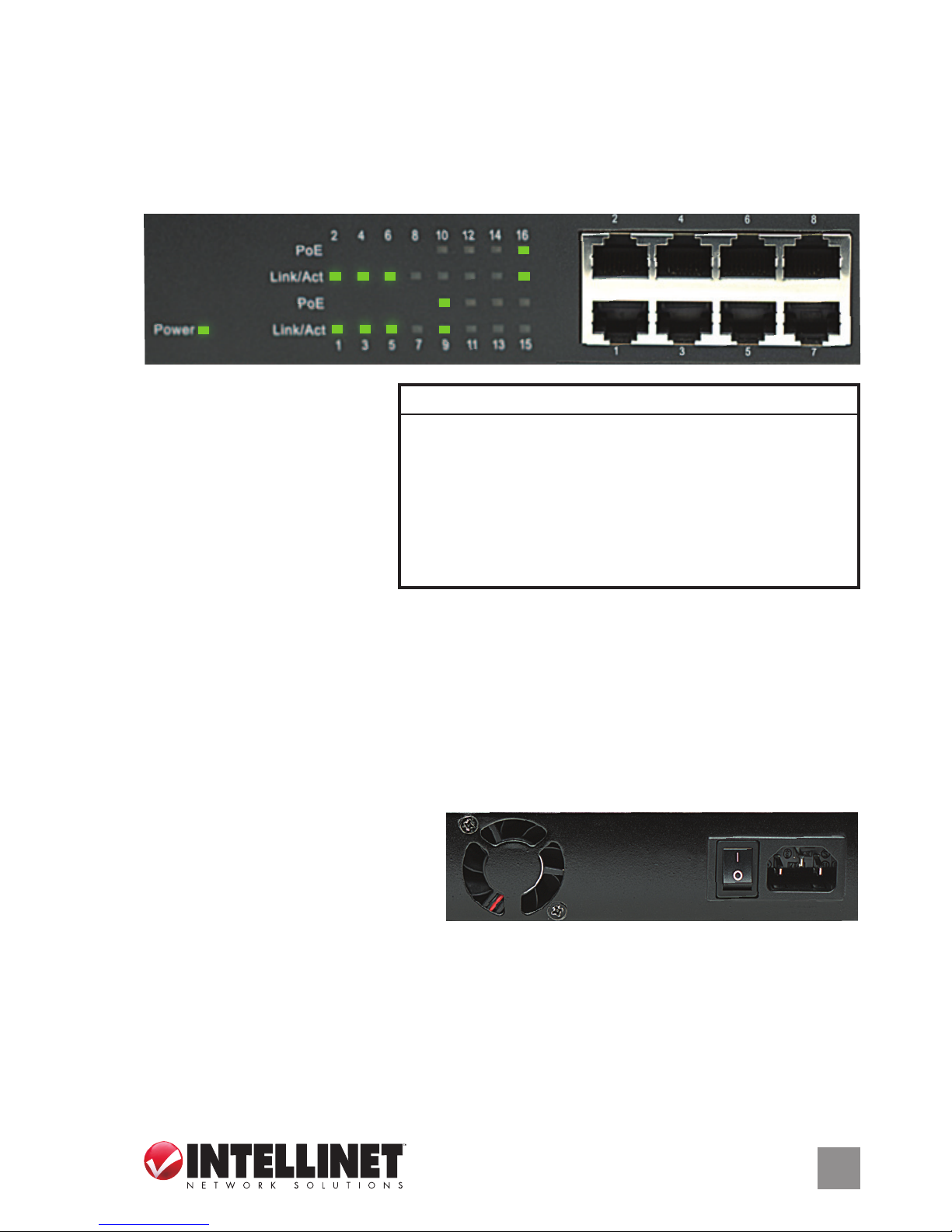
ANSCHLÜSSE & ANZEIGEN
LED-Anzeigen
Die LEDs — Strom, PoE,
Verbindung/Aktivität —
vereinfachen das Ablesen der
Funktionen und Anschlüsse.
HINWEIS: Können nur die
Ports 9-16 angeschlossene
Geräte mit Strom versorgen;
diese sollten mit IEEE 802.3af kompatibel sein.
Ports
Alle Ports unterstützen Auto-MDI/MDI-X Funktionalität, daher werden Crosskabel und
Uplink-Ports für Verbindungen zu PCs, Routern, Hubs, anderen Switchen, etc. nicht
benötigt. Cat5/5e- UTP/STP-Kabel bieten die beste Performance. Wenn eine LED keine
Verbindung/Aktivität anzeigt, überprüfen Sie das verbundene Gerät.
Strom
Schließen Sie das beiliegende
Stromkabel an das Gerät (neben
dem An/Aus-Schalter) und an eine
Steckdose an. Vergewissern Sie sich
dass die “Power”-LED aueuchtet.
INSTALLATIONSTIPPS
Es wird empfohlen, den Switch vor der Nutzung folgendermaßen aufzustellen:
• auf ebenem Untergrund mit mind. 25 mm Rundumabstand für ausreichend Luftdurchsatz
• fern von anderen Übertragungsgeräten wie Radio, Breitbandverstärker, etc.
• max. 100 m vom zu verbindenden Netzwerkgerät entfernt.
LED Status Operation
Power An Gerät wird mit Strom versorgt
Aus Stromanschluss prüfen/Gerät einschalten
PoE An Port ist mit PSE/PoE-Gerät verbunden
Aus Kein PSE/PoE-Gerät angeschlossen
Link/Act An Verbindung ist hergestellt
Blinkend Verbindung ist hergestellt; Datenübertragung
Aus Verbindung ist nicht hergestellt
On
Off
Power
1 3 5 7 9 11 13 15
2 4 6 8 10 12 14 16
PoE
PoE
Link/Act
Link/Act
1 3 5 7
2 4 6 8
16 RJ45 10/100M Ports (Auf Abb:1-8)
4
ESPAÑOL
Switch PoE Fast Ethernet de 16 puertos para Montaje en Rack • Manual del usuario Español
Gracias por comprar el Switch PoE Fast Ethernet de 16 puertos para Montaje en Rack
de INTELLINET NETWORK SOLUTIONS™, Modelo 560405.
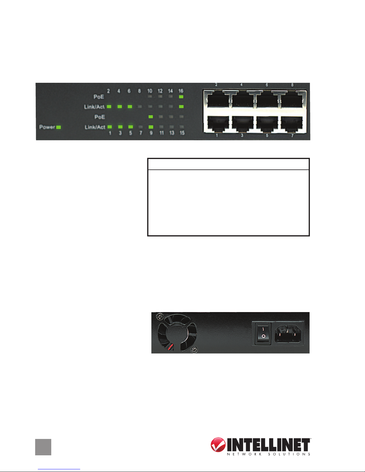
CONEXIONES E INDICADORES
LEDs
Los LEDs — Power, PoE Link/
Activity — hacen mas facil
monitorear el switch y sus
conexiones. NOTA: únicamente los
puertos del 9-16 pueden proveer
energia a los dispositivos, todos
los dispositivos deben cumplir con
IEEE 802.3af.
Puertos
Todos los puertos del switch soportan Auto-MDI/MDI-X , los cables crossover y puertos
de enlace no son necesarios para las conexiones para PCs, routers, hubs, otros switches,
etc. los cables Cat5/5e UTP/STP proporcionan un redimiento optimo; Si un LED no
indica conectividad ó actividad, compruebe las conexiones sean adecuadas.
Alimentación
Utilice el cable de alimentación
incluido para conectar el dispositivo
(junto al switch On /O) a una toma
de CA. Conrme que el LED en el
panel frontal está encendido.
TIPS DE INSTALACION
Antes de utilizarlo, se recomienda que switch es ubicado/jado:
• sobre una supercie plana con al menos 25 mm de espacio libre para ventilación;
• lejos de fuentes de ruido: radios, transmisores, amplicadores de banda ancha, etc.;
• dentro de los 100 m (aprox. 328’) deben estar conectados los dispositivos de red.
Power
1 3 5 7 9 11 13 15
2 4 6 8 10 12 14 16
PoE
PoE
Link/Act
Link/Act
1 3 5 7
2 4 6 8
On
Off
16 RJ45 10/100M puertos (1-8 se muestra)
LED Status Operación
Power Encendido Encendido
Apagado Revise la conexión AC ; encienda de nuevo
PoE Encendido Puerto vinculado a un dispositivo PSE/PoE
Apagado No hay un dispositivo PSE/PoE conectado
Link/Act Encendido Valide el puerto de conexión
Parpadeo Datos trasmitidos /recibidos
Apagado No hay comunicación
 Loading...