

Intellinet 503181, 550178, 550253, 550796 User Manual
(rev. 4-07) INT-503181/550178/550253/550796-UM-1106-02

2
Table of Contents
Safety and Regulatory Notices................................................................................................................................. 3
Section 1: Product Overview .................................................................................................................................... 5
1.1 About the Pro Series (MPEG4) Network Camera ...................................................................................... 5
1.2 Main Features and Benefits.......................................................................................................................... 5
Section 2: Physical Description ............................................................................................................................... 6
2.1 Package Contents.......................................................................................................................................... 6
2.2 Front View and LEDs..................................................................................................................................... 7
2.3 Rear View ........................................................................................................................................................ 7
Section 3: Installation Summary .............................................................................................................................. 8
Section 4: Assigning an IP Address & Accessing the Camera’s Homepage.................................................... 8
4.1 Assigning an IP Address .............................................................................................................................. 8
4.2 Assigning an IP Address Using IP Installer ............................................................................................... 9
4.2.1 Connecting the Camera to a PC ............................................................................................................ 9
4.2.2 Using IP Installer...................................................................................................................................... 9
4.3 Assigning an IP Address Using HyperTerminal........................................................................................ 10
4.3.1 Configuring HyperTerminal.................................................................................................................... 10
4.3.2 Using HyperTerminal............................................................................................................................... 11
4.4 Accessing the Camera’s Homepage ........................................................................................................... 13
4.4.1 Starting the Web Browser.......................................................................................................................... 13
4.4.2 Login Page ................................................................................................................................................... 13
4.4.3 MPEG4 Network Camera Homepage........................................................................................................ 15
Section 5: Adjusting the Camera Lens.................................................................................................................... 16
5.1 Adjusting the Focus ...................................................................................................................................... 16
5.2 Replacing the Lens ........................................................................................................................................ 16
Section 6: Configuring Administrator Tools .......................................................................................................... 17
6.1 Overview of the Administrator Menu .......................................................................................................... 17
6.2 Image Configuration...................................................................................................................................... 18
6.3 Network Configuration .................................................................................................................................. 21
6.4 User Configuration ........................................................................................................................................ 23
6.5 Event Trigger Configuration......................................................................................................................... 25
6.6 System Configuration ................................................................................................................................... 28
6.7 Wireless Configuration ................................................................................................................................. 30
6.7.1 Wireless Setup ......................................................................................................................................... 30
6.7.2 Wireless Security Settings ..................................................................................................................... 30
Section 7: PoE Support ............................................................................................................................................. 32
Section 8: Multi-Viewer Application for Windows ................................................................................................. 33
8.1 Installation....................................................................................................................................................... 33
8.2 Usage ............................................................................................................................................................... 34
Section 9: Remote Access to a Camera Installed behind a Router .................................................................... 36
9.1 Preparation ..................................................................................................................................................... 36
9.2 Setup Examples ............................................................................................................................................. 37
Section 10: Developer Information .......................................................................................................................... 38
10.1 CGI Commands ............................................................................................................................................. 38
10.2 Direct Image Access to Internal JPGs ....................................................................................................... 39
10.3 Web Page Integration (ActiveX for Microsoft Internet Explorer) ........................................................... 40
Appendix A: Technical Specifications .................................................................................................................... 42
Appendix B: Frequently Asked Questions (FAQ).................................................................................................. 43
Appendix C: Troubleshooting .................................................................................................................................. 44
Appendix D: Utilizing IP Addresses on a Local Network ..................................................................................... 47
Appendix E: Updating Firmware .............................................................................................................................. 49
Appendix F: The I/O Connector................................................................................................................................ 50
Appendix G: Dynamic Domain Name System (DDNS).......................................................................................... 51
Appendix H: High-Speed Solutions......................................................................................................................... 56
Appendix I: Reinstating the Factory Default Settings .......................................................................................... 57
Appendix J: Glossary of Terms................................................................................................................................ 58

3
Thank you for purchasing this INTELLINET NETWORK SOLUTIONS™ Pro Series Network
Camera, Model 503181 or 550796, or Pro Series Wireless Network Camera, Model 550178 or
550253. This user manual, applicable for software releases 2.0 and later, includes instructions
for using and managing the camera on your network. Previous networking experience will be
helpful when setting up and using this product, and some knowledge of UNIX or Linux-based
systems may also be beneficial for developing shell scripts and applications. Later versions of
this document will be posted to www.networkipcamera.com as required.
Electromagnetic Compatibility (EMC)
This equipment generates radio frequency energy and, if not installed and used in accordance
with the instructions, may cause harmful interference to radio communications. However, there
is no guarantee that interference will not occur in a particular installation. If this equipment does
cause harmful interference to radio or television reception, which can be determined by turning
the equipment off and on, the user is encouraged to try to correct the interference by one or
more of the following measures:
• Re-orient or relocate the receiving antenna.
• Increase the separation between the equipment and receiver.
• Connect the equipment to an outlet on a different circuit than the receiver.
• Consult your dealer or an experienced radio/TV technician for help.
• Check that shielded (STP) network cables are being used with this unit to ensure compliance
with EMC standards.
This equipment has been tested and found to comply with the limits for a Class B computing
device pursuant to Subpart B of Part 15 of FCC rules, which are designed to provide
reasonable protection against such interference when operated in a commercial environment.
Operation of this equipment in a residential area is likely to cause interference, in which case
the user, at his own expense, will be required to take whatever measures may be required to
correct the interference.
This digital equipment fulfills the requirements for radiated emission according to limit B of
EN55022/1998, and the requirements for immunity according to EN55024/1998 residential,
commercial and light industry.
Safety
This equipment (Wireless Models 550253 and 550178) complies with EN 60950, Safety of
Information Technology equipment.
Radio Transmission Regulatory Information
This equipment generates and radiates radio frequency energy, and must be installed and
operated while maintaining a minimum body-to-camera distance of 3 feet (1 meter).
Tested to comply with FCC Standards FOR HOME OR OFFICE USE.
This product must be installed and used in strict accordance with the instructions given in the
user documentation.
This product complies with the following radio frequency and safety standards:
Europe — EU Declaration of Conformity. This device complies with the requirements of the
R&TTE Directive 1999/5/EC with essential test suites as per standards EN 301489: General
EMC requirements for radio equipment; and ETS 300328: Technical requirements for radio
equipment.
USA — Federal Communications Commission (FCC): This device complies with Part 15 of
FCC Rules. Operation of the device is subject to the following two conditions:
1. This device may not cause harmful interference.
2. This device must accept any interference that may cause undesired operation.

4
Video Standard and Product Classification
As the video standard varies from country to country, users are asked to check it first and
choose the right model. The two most common video standards used are NTSC and PAL.
NTSC is the video system or standard used in North America and most of South America. In
NTSC, 30 frames are transmitted each second. Each frame is made up of 525 individual scan
lines.
PAL is the predominant video system or standard mostly used overseas. In PAL, 25 frames are
transmitted each second. Each frame is made up of 625 individual scan lines.
Below are the four Pro Series Network Cameras represented in this user manual with their
appropriate standard.
503181: Wired MPEG4/JPEG Dual Mode Network Camera for NTSC standard
550796: Wired MPEG4/JPEG Dual Mode Network Camera for PAL standard
550253: Wireless and wired MPEG4/JPEG Dual Mode Network Camera for NTSC standard
550178: Wireless and wired MPEG4/JPEG Dual Mode Network Camera for PAL standard
To determine your video standard, refer to the lists below.
PAL: Afghanistan, Algeria, Argentina (N), Austria, Australia, Bangladesh, Belgium, Brazil (M), China,
Denmark, Finland, Germany, Hong Kong, Iceland, India, Indonesia, Iraq, Ireland, Israel, Italy, Jordan,
Kenya, Kuwait, Liberia, Malaysia, Netherlands, Nigeria, Norway, New Guinea, Pakistan, Singapore,
South Africa, Southwest Africa, Sudan, Sweden, Switzerland, Thailand, Turkey, Uganda, United
Kingdom, United Arab Emirates, Yugoslavia, Zambia
NTSC: Canada, Chile, Costa Rica, Cuba, Dominican Republic, Ecuador, Japan, Mexico, Nicaragua,
Panama, Peru, Philippines, Puerto Rico, South Korea, Taiwan, U.S.A.
Important Notices
1. Camera surveillance laws may differ for each country. Contact the local
authorities to avoid any surveillance law violations.
2. Note that the CCD lens that comes with the Pro Series Network Camera
can be damaged permanently if exposed to direct sunlight. If your
application demands prolonged exposure to sunlight, you should consider
equipping it with a sun visor.
3. The Pro Series Network Camera is not weatherproof. Be aware of
environmental specifications included in the manual. For outdoor use, use
a weatherproof case to protect the camera from water, moisture or
temperature (higher or lower than specifications). For camera cleaning,
gently wipe with a clean, dry cloth.
4. Be sure to use only the DC adapter provided with your camera. Connecting
the camera directly to AC current may cause electrical damage to the
camera.
5. Be careful when handling the camera. Physical shocks can cause serious
damage.
6. Be sure to mount the camera securely to avoid any personal injuries. Keep
the camera out of reach of children.
7. If the camera does not operate properly, contact your local distributor. Do
not disassemble the product, as that may void the warranty.
5
1 Product Overview
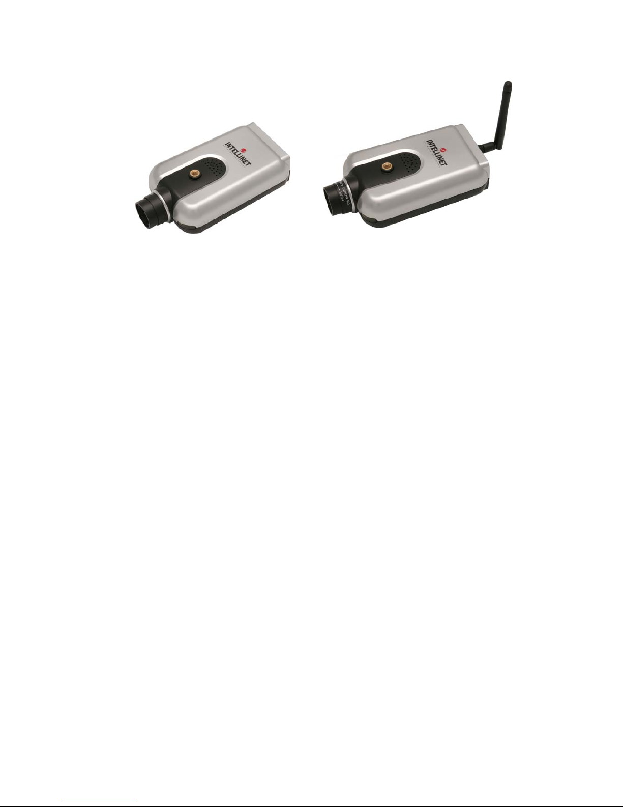
1.1 About the Pro Series (MPEG4) Network Camera
Models 503181, 550796 Models 550253, 550178
The Pro Series Network Camera is an all-in-one networking device that contains a digital color
camera, a powerful Web server, an optimized embedded operating system, hardware for image
compression and a physical Ethernet connection. The camera does not need any additional
software or hardware. Simply provide power, connect an Ethernet cable and view from any
computer on the network.
The INTELLINET NETWORK SOLUTIONS Pro Series Network Camera is ideal for surveillance
applications that require high-quality, full-motion video and audio, as well as comparatively low
bandwidth demands on the network. This camera provides an easy user interface for remote
access to receive the optimal synchronized video and audio from anywhere, anytime over the
Internet with the popular Internet Explorer Web browser, as easy as surfing any regular Web
sites. More than just a high-performance network camera, the Pro Series Network Camera also
offers many advanced features to provide personal or SI solutions, such as remote
surveillance, home/business security, audio/video conferencing, motion detection and more.
1.2 Main Features and Benefits
Convenient Operation
The Pro Series Network Camera does not need any additional software or interaction with any
other server. The only software needed is a common Web browser, such as Microsoft Internet
Explorer 5.x or above.
Open Standards
The Pro Series Network Camera supports TCP/IP networking, SMTP email, FTP, HTTP and
other Internet-related protocols. The camera can be used in a mixed operating system
environment with Windows, Unix, Mac and OS/2. It integrates easily into other www/Intranet
applications and CGI scripts.
Simple Administration
Using a standard Web browser, you can configure and manage the Pro Series Network
Camera directly from its own embedded Web pages. The embedded operating system is
upgradeable through the network; check with your local INTELLINET NETWORK SOLUTIONS
dealer for firmware upgrades.
External Devices
The auxiliary Input/Output connector on the camera allows you to connect to a variety of
external devices, such as IR sensors, switches and alarm relays.
Security
Your Pro Series Network Camera includes a self-contained Web server, which means that

6
digital images can be secured like any other Internet host. Your network administrator, using
the unit’s security settings in combination with an organization’s Internet firewall, normally
implements data protection. The administrator can decide whether individuals, groups or the
whole world may access the camera. The Pro Series Network Camera supports multi-user
password protection.
Compression and Performance
With a variable frame rate dependent on the image quality and bitrate, the camera delivers
MPEG4 video at up to 30 images per second.
Dual Mode Compression
For application providers, system integrators and other APs, this camera supports JPEG
compression as well as MPEG4 video.
Full Duplex Two-Way Audio Supported
Full duplex two-way audio is available by connecting an external microphone and speaker to
the camera.
IEEE 802.3af Standard PoE (Power over Ethernet) Supported
Software
IP Installer for quick installation
Multi-Viewer for viewing four cameras
2 Physical Description
2.1 Package Contents
Check all items packed inside the box as listed below.
ITEM
DESCRIPTION
REMARKS
Network Camera
MPEG4 Network Camera
Installation CD
IP Installer, upgrade program,
manual, Multi-Viewer, etc.
Program CD
Power Supply
AC power adapter and power cord
AC adapter (110 V – 240 V)
and black power cable
Stand
Wall & table stand*
Sturdy iron construction
Connection
Cable
RS-232 cable
Black
User Manual
Hard-copy book
* You can use a standard camera stand or tripod for the Pro Series (MPEG4) Network Camera.
7
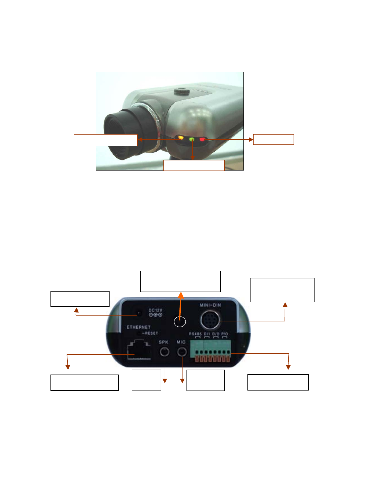
2.2 Front View and LEDs
Power LED (Red): Once power is supplied to the camera, the red LED will light.
Operating Status LED (Green): This LED indicates the camera’s operating status. Once
power is supplied, the LED lights and then blinks once every second as long as the video is
transmitted on the network during normal operation. When there is no video transmission, the
LED stops blinking. Under an event-trigger situation, the green LED becomes red and blinks
rapidly. During simultaneous operation of event-trigger capture and video monitoring, it blinks
rapidly and alternates between red and green.
Network Activity LED (Yellow): This LED indicates network activity. When lit, the network is
up and running; when off, the network is down and not working.
2.3 Rear View
Power Connector: Only use the supplied AC adapter so as to avoid any possible damage
from
electric shock.
Network Connector
Mini DIN for
Zoom/Focus Control/
RS-232 Communication
Power Connector
GPIO Connector
External
Speaker
External
Microphone
Power LED
Operating Status LED
Network Activity LED
Wireless Antenna
(Models 550253, 550178)

8
Network Connector: Connect 10Base-T Ethernet or 100Base-TX Fast Ethernet cable.
GPIO Connector: To connect external devices such as infrared sensors, alarms or motion
detectors (refer to Appendix F: I/O Connector).
Mini DIN Connector: To connect external devices such as the external zoom/focus lens
mechanism, or to connect directly to a serial port for camera configuration via HyperTerminal.
SPK: Use to connect to an external speaker for audio communication. The audio sent over the
network from a connected camera client can be delivered through this externally connected
speaker.
MIC: The external microphone for audio input. The live audio can be captured and transmitted
to the connected camera client via the use of this MIC.
RESET: Restore the factory default settings.
3 Installation Summary
1. Connect the Ethernet and power to the Pro Series Network Camera.
2. Install and launch the IP Installer program on the enclosed CD.
3. Assign an IP address and network settings
4. Securely mount the camera.
5. Adjust the lens focus.
4 Assigning an IP Address & Accessing the Camera’s
Homepage
4.1 Assigning an IP Address
To access the camera, you need to assign an appropriate network IP address.
Install the IP address installation program (IP Installer.exe) on a PC that is connected to the
same local network as the camera.
Network IP Address:
A network IP address is an identification code for computers or devices on a
TCP/IP network. Networks using TCP/IP protocols route messages based on
the IP address of the destinations within a closed network. IP addresses can be
assigned at random as long as each one is unique. However, connecting a
private network to the Internet requires using registered, public IP addresses to
avoid duplicates. An IP address can be acquired from a network administrator
or an Internet service provider. IMPORTANT: Use the newly assigned IP
address, and NOT any occupied IP address or the default or example IP
address. It is highly recommended that you assign an IP address before placing
the camera in a remote location or remote network.
MAC (Ethernet) Address (Media Access Control Address):
A MAC address is a hardware identification code that uniquely identifies each
device of a network. The MAC layer interfaces directly with the network media.
Consequently, each type of network media requires a different MAC layer. The
MAC address of your Pro Series Network Camera is a 12-digit number. A
unique MAC address can be found on the label at the bottom of each camera.
9
4.2 Assigning an IP address Using IP Installer
4.2.1 Connecting the Camera to a PC
1. Connect with a direct cable (non-crossover UTP cable) when connecting the camera to a
switch, hub or router.
2. Connect with a crossover UTP cable when connecting the camera to a PC.
4.2.2 Using IP Installer
To install an IP address, you should use the IP Installer provided with the Pro Series Network
Camera. You can download its program through the Web site: http://INTELLINET NETWORK
SOLUTIONS-network.com. NOTE: The minimum requirement for IP Installer is Windows
9x/NT/2000.
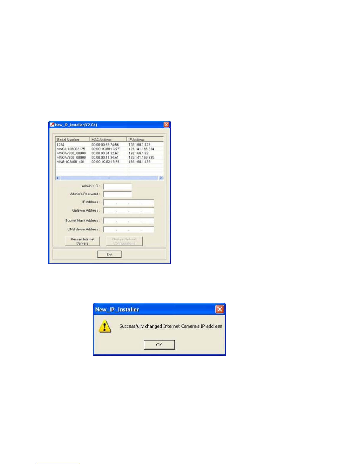
1. Run IP Installer after the camera is done
booting (wait until the Operating Status LED
blinks every second).
2. Once IP Installer is run, the panel shows
every camera connected on the local
network. From the cameras listed, select one
to assign a new IP address (every Pro Series
Network Camera has a factory default IP
address).
NOTE: The MAC address can be found on
the underside label of the camera. To choose
a camera, click on its MAC address on the
list.
3. Enter the administrator ID and password in
the blank (default ID and password are both
“admin”) to assign or change the IP address
for the camera and setup.
4. Enter the IP address, gateway address,
subnet mask address, DNS server address
and server IP address assigned by the
network administrator. (When the addresses
are not assigned properly, you cannot access the camera.) The server IP address represents
an IP address of a PC being used to execute the upgrade program when updating the
camera (refer to Appendix E: Updating Firmware).
5. After entering all addresses for the camera, click on “Change Network Configurations.”
The message shows up if all the information is set up properly. Then click the “OK” button.
NOTE: After changing the network configuration, it may take a little time to reboot the camera
in order to access the camera’s homepage.
10
4.3 Assigning an IP Address Using HyperTerminal
NOTE: This section is for advanced users only. This procedure is not normally required.
4.3.1 Configuring HyperTerminal
HyperTerminal is a basic program for Windows 9x/NT/2000. A PC can communicate with
external devices through the serial port by using this program. The steps you should take to set
the HyperTerminal are as follows with a Windows 2000 OS:
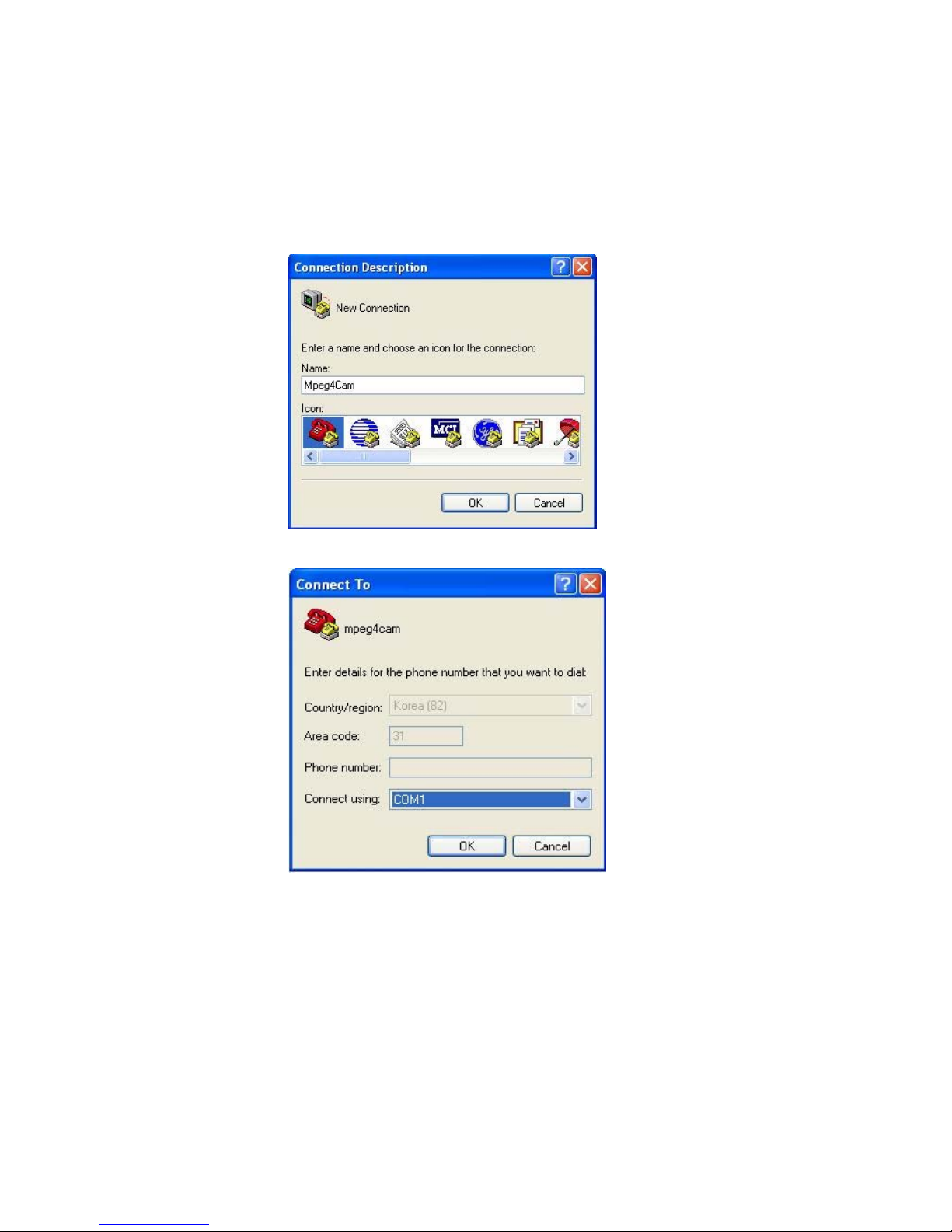
1. Go to Start Programs Accessories Communications HyperTerminal. Select one of
the icons and then enter an appropriate name in the box.
2. Select a serial port of the PC, then click “OK.” (Usually COM1 or COM2 is recommended.)
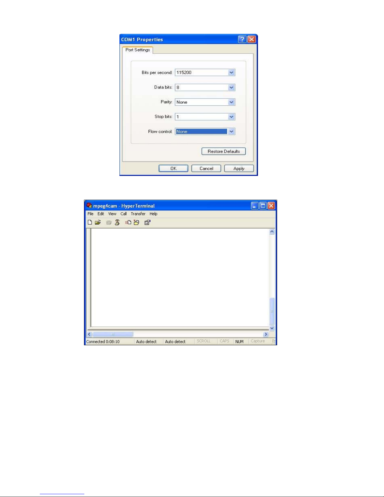
3. Configure bit/sec as 115200 and leave other settings at the default values.
11
4. The window should display as below when configured properly. (If it doesn’t, try again from
the beginning.)
4.3.2 Using HyperTerminal
Follow these steps to assign an IP address using HyperTerminal.
1. Run HyperTerminal on your PC.
2. Connect the RS-232 cable from the serial port of the PC (selected in section 4.3.1:
Configuring Hyper Terminal) to the camera serial port while HyperTerminal is active.
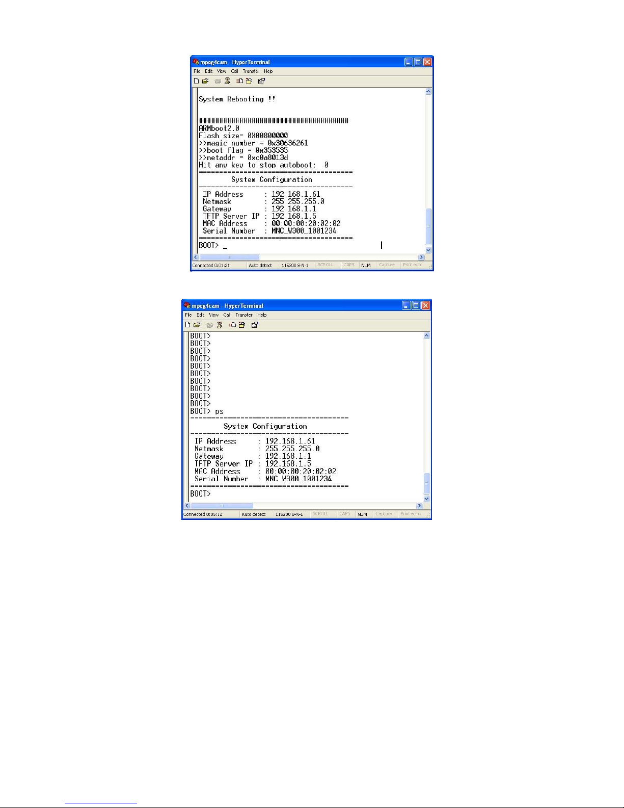
3. Turn the camera on.
4. A countdown will start with the message “Press any key to stop auto-boot.”
5. Press any key to display the “Boot” screen as shown below.
12
NOTE: You can view the network configuration while the boot window is on screen by entering
“ps” again.
Here, the IP address, netmask, gateway, TFTP server and MAC address (Ethernet address)
values are network configuration values. You should change these values in most cases. If you
don’t know what value you should assign, refer to the network administrator.
IP Address and subnet mask addresses are separated by colon (:). For example, the IP
address is represented by decimal numbers delimited by a dot (.) like “192.168.1.27.”
Hexadecimal numbers like “ffffff00” (in the case of 255.255.255.0) represent a subnet mask
address. Note that the numbers of the subnet mask value are not delimited by a dot.
Gateway (g) is the gateway address of the camera.
TFTP Server IP is the address to which the camera tries to connect to upgrade its firmware
program in flash memory. The camera first searches this host on the network during the
booting sequence. For information on any Pro Series Network Camera upgrade, refer to
Appendix E.
MAC Address is the Ethernet address of Network Camera.
13
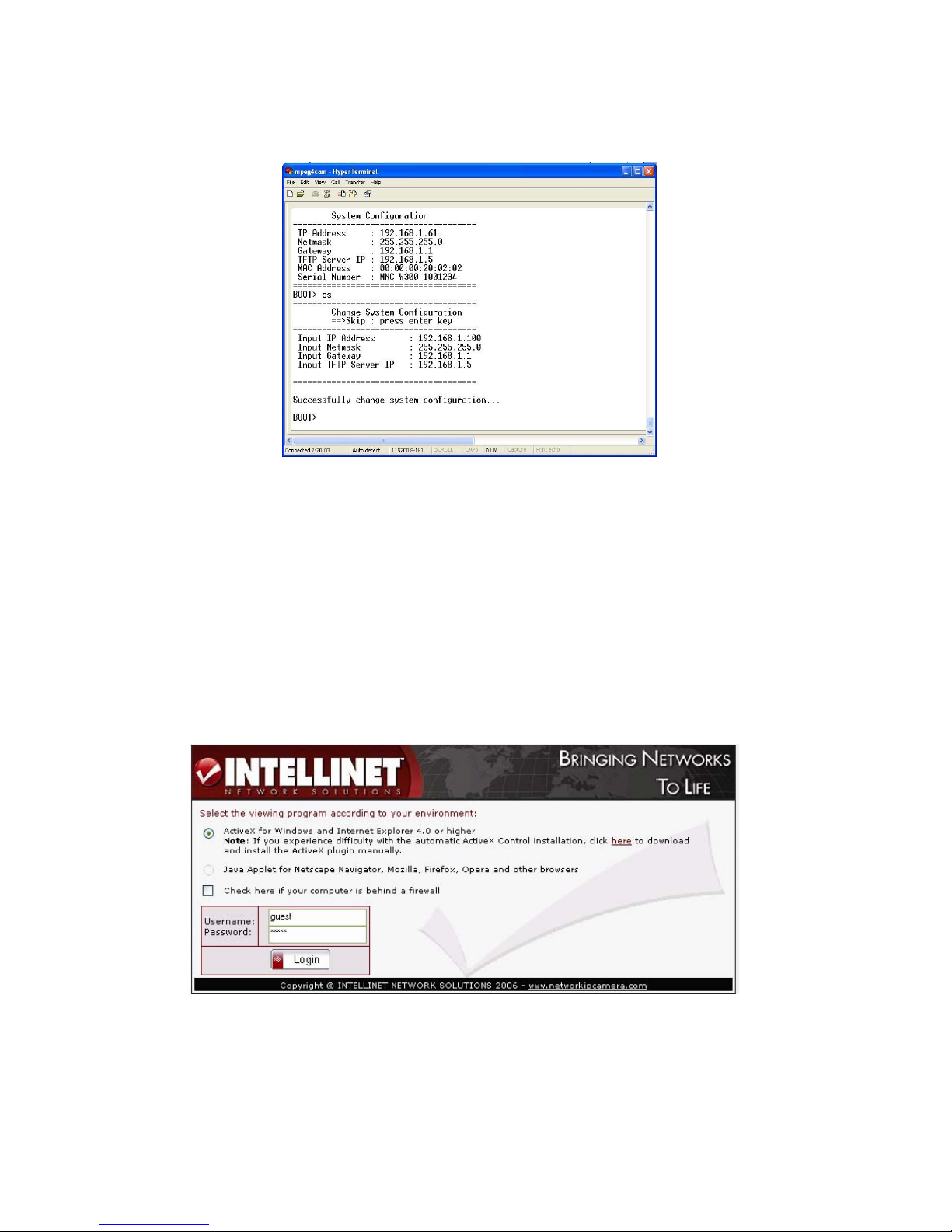
NOTE: Enter “cs” to change the network configuration during the boot prompt. If you enter “cs,”
the camera shows you the information for which you can change values and the current
assigned values. You can make changes as shown below.
When you terminate the HyperTerminal program after you have changed the network
configuration, it asks if you wish to save the session. If you save the session, you can re-use
HyperTerminal. To re-use the session you saved, click Start Programs Accessories
Communications HyperTerminal MPEG4 Network Camera.ht (with Windows XP/2000).
4.4 Accessing the Camera’s Homepage
After assigning an IP address, you can access the camera and monitor real-time images over
the Internet. You can configure the camera within its own pages through any standard Web
browser on a local or remote network.
4.4.1 Starting the Web Browser
Start your Web browser, entering your camera’s IP address on the address bar in order to
access the login page. The default IP address is 192.168.1.221.
4.4.2 Login Page
Select a viewing program
Users of Windows/MS Internet Explorer should select ActiveX. All other users should select
Java Applet.
14
Username and Password
Enter a username and password to access the camera. The camera has two default user
accounts.
• Administrator account: To view the live image and change the camera settings.
Username: admin
Password: admin
• Guest account: To view the live image, but not access any camera settings.
Username: guest
Password: guest
Behind a Firewall
If your PC is connected to a network with a firewall, you may not view real-time video properly
because the video TCP port is blocked. Whenever you can see the login page in your Web
browser but no live video shows up on the main camera live screen, you should activate this
option.
ActiveX for MS Explorer Users
For all Microsoft Explorer users, the ActiveX Control program is required. The program will be
installed automatically when a user accesses the camera. For ActiveX installation on your PC,
just click “Yes” to the question “do you want to install the program?” on the pop-up window. If
you cannot see images after installation, you should download and install ActiveX manually.
The link is provided on the login page of the camera.
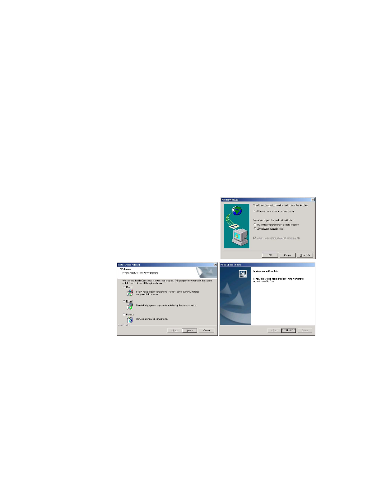
Manual Installation of ActiveX
If the ActiveX program fails to install automatically, you
can install it manually.
1. When the first window displays, click “Open” to
install the program.
2. After the download, the InstallShield Wizard window
displays. Check “Repair” and click “Next.”
3. When ActiveX installation is complete, click “Finish”
and return to the login page to access the camera’s
homepage.
Java Applet for Macintosh or Unix System Users
Java Applet is designed for all operating systems and virtually all Web browsers, including Mac
OS and Linux-based systems, and Web browsers like Firefox, Mozilla, Opera and many more.
NOTE: The camera’s ActiveX program is based on an MS Windows OS. Therefore, it is
impossible to access the camera and monitor real-time images through a default viewer. If a
user accesses the camera through Macintosh or Unix systems, the camera detects that the OS
is not MS Windows and it operates a Java-based image viewer to show real-time images.
Some functions are not available for Java Applet.
It is highly recommended that Internet Explorer 4.0 or higher is selected for the ActiveX viewer
for Windows 95/98/2000/NT. Otherwise, selected the Java Applet viewer.
15
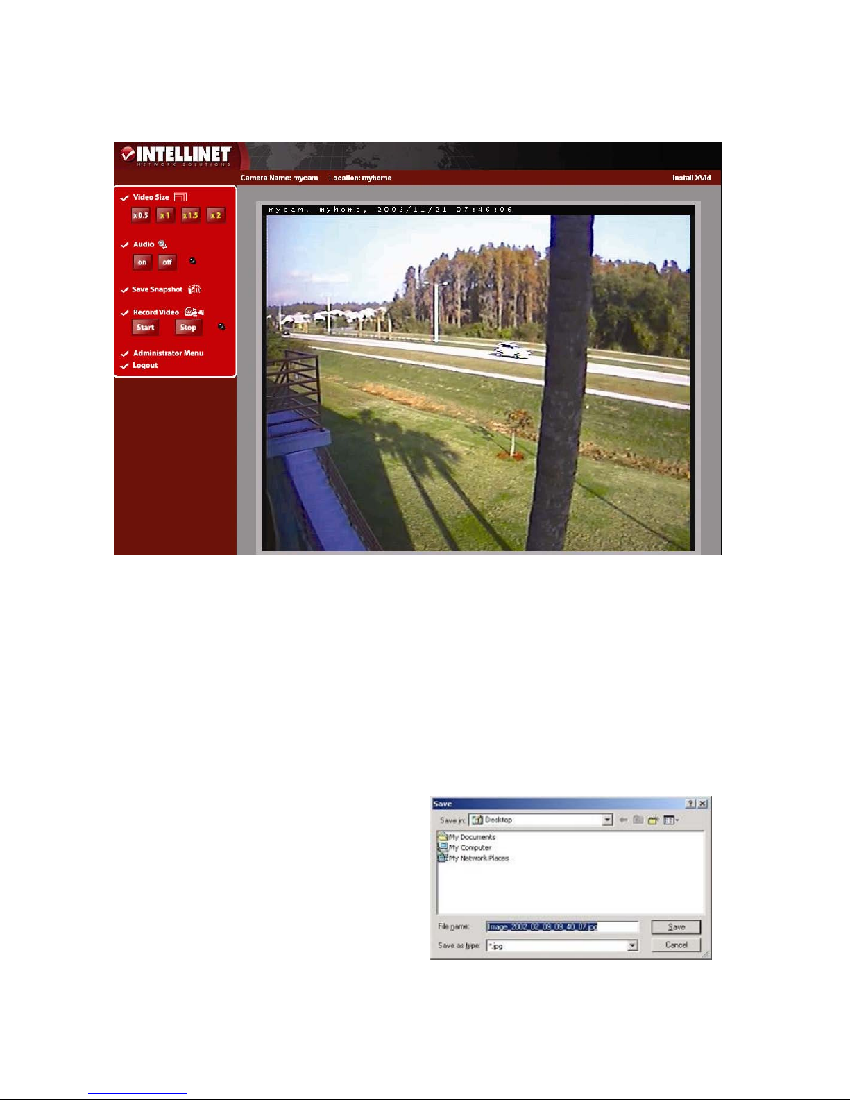
4.4.3 MPEG4 Network Camera Homepage
Once the login procedure is complete, you can view the Pro Series (MPEG4) Network Camera
homepage.
Video Size
You can select a viewing image size from 0.5 to 2. This function may be used when you want to
expand the image size on your PC. (Resolution can’t be changed at all.)
Audio
Select audio “On” for starting audio communication; select “Off” to stop audio communication
over the network with the external microphone and speaker connected to the camera.
Administrator Menu
This button is for accessing the administration menu. However, only the user who has authority
as an administrator can access the page with administrator’s ID and password (see Configuring
Administration Menu).
Logout
User can go back to the Login page by using the “Logout” button.
Save Snapshot
To save only one image, press the “snapshot”
button and then select a folder. The image is
saved as a JPEG file (with the default file
name composed of the date and time:
image_yyyy_mm_dd_hh_mm_ss.jpg).
Record Video
Users can save real-time images from the
camera on a PC. Click “Start,” then select the
folder to save the images in. (The image is
16
saved as an AVI file.) Once the camera starts to save images, the green LED indicator will start
blinking. To stop saving, click “Stop” and the LED indicator will stop blinking.
Camera Name & Location
Through the system configuration menu, you can set a camera name and location (see section
6.6: System Configuration).
NOTE: You can view a saved image with Windows Media Player or RealTime. For the initial
playback of a saved image, click “Install XviD.” The AVI save will be split every 20 minutes (for
example: file name 2002_04_22_15_00, file name 2002_04_22_15_20…).
5 Adjusting the Camera Lens
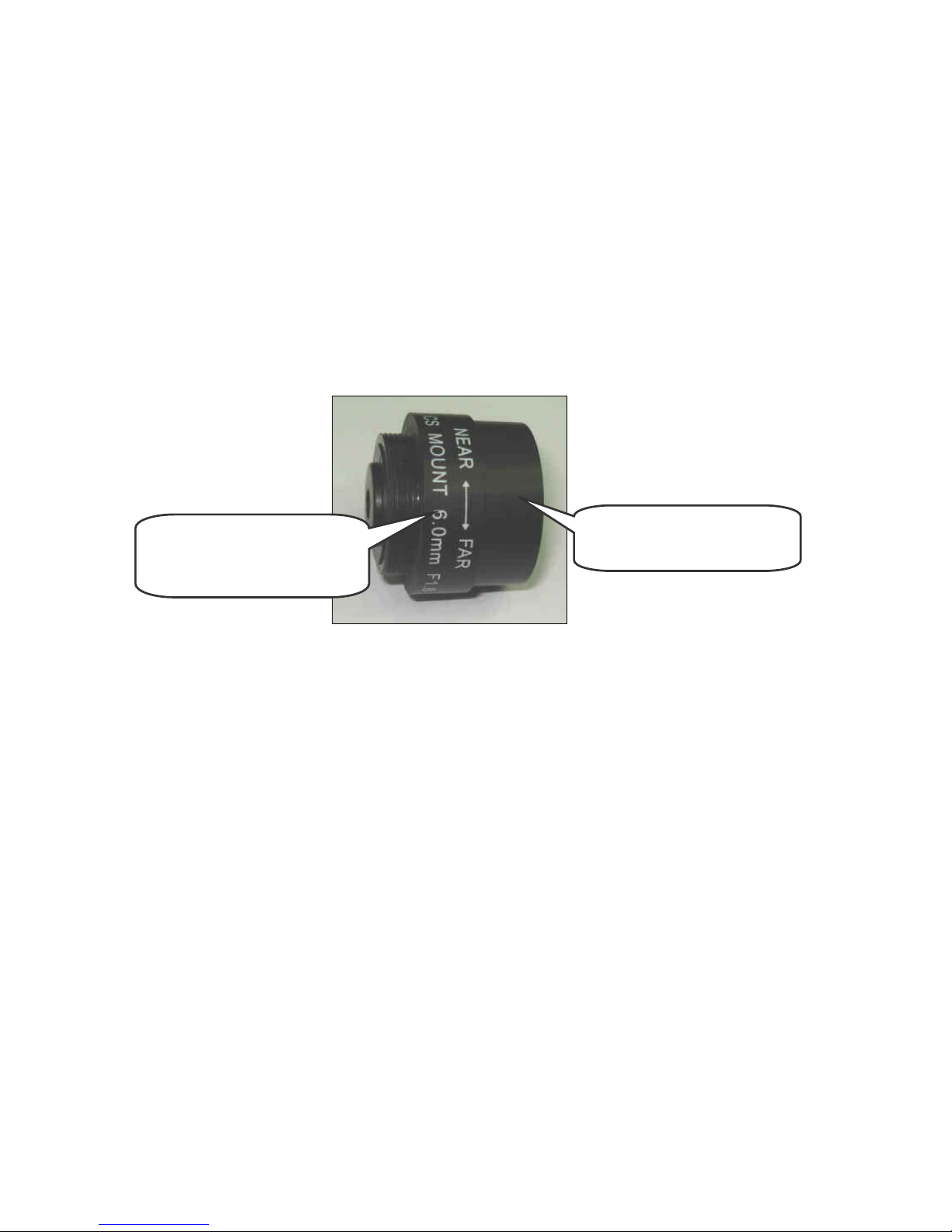
5.1 Adjusting the Focus
To get the finest image, adjust the lens focus according to your environment. To make this
adjustment, simply turn the lens in either direction till you get the most well-defined image
edges while viewing the picture quality on your Web browser.
NOTE: Do not force the lens beyond either the clockwise or counterclockwise limit. Also, a good
level of focus is normally achievable throughout several planes within the camera’s focusing
spectrum. Since optimum focusing is dependent upon the camera’s field of view, it is important
to scan the focusing plane from the closest to furthest perspectives before attempting
any fine-tuning.
5.2 Replacing the Lens
The Pro Series Network Camera is designed with a CS mount. The lens supplied with your
product can be replaced with any standard C or CS lens, typically used within the surveillance
industry. Follow the instructions below to replace the supplied lens with any C or CS type lens.
1. Unscrew the camera lens by turning the lens counterclockwise (see above).
2. For C lens only: Attach the new lens to a C-CS adapter.
3. Screw the new lens onto the camera. If applicable, adjust the iris according to the prevailing
light conditions.
4. Focus the lens as instructed above.
5. Reload your Web browser and monitor the results from the product home page.
Turn this part either clockwise
or counterclockwise to adjust
the lens focus.
Turn this part counterclockwise
(with the lens facing you) to
unscrew the lens for
replacement.

17
6 Configuring Administrator Tools
You can control the configurations of the camera using the administrator tools, which can be
accessed only by an authorized user. If non-authorized users try gaining access, you may see
the caution message “You are not an administrator.”
6.1 Overview of the Administration Menu
The table below provides a one-step overview of the Administrator Tools:
Image Configuration
To Configure compression rate, image size, brightness, contrast, etc.
Network Configuration
To configure camera IP, Web server port, image transfer port
Admin, User Configuration
To configure user ID and password
System Configuration
TO CONFIGURE THE CAMERA NAME, LOCATION AND TIME SETTINGS
Event Trigger Configuration
To configure trigger condition, image capture option, trigger output, etc.
Wireless Configuration
(wireless models only)
To configure wireless parameters such as wireless mode, SSID,
encryption, etc.
Return to Live View
To go back to the monitoring page
18
To prevent any unauthorized use of the camera, access is strictly restricted to defined users.
Administrator(s) has exclusive access to the administrator tools, and can determine the
registration and access rights for all users.
Enter your ID and password, then click “Submit” (default ID and password are all “admin”).
NOTE: Although the administrator’s default username and password (set to “admin” for all)
can be used for logging in to the unit for the first time, it is highly recommended that you
change this password for your camera as soon as possible since all Pro Series Network
Camera products are shipped with the same ID and password as defaults. Also, make sure to
click “Submit” after verifying any reset configuration; otherwise, it won’t be changed.
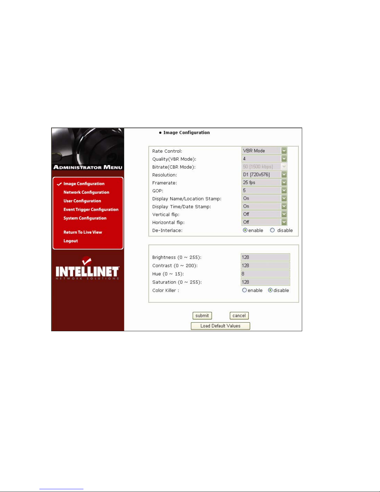
6.2 Image Configuration
Rate Control
Select the rate control by selecting the VBR (variable bitrate) or CBR (constant bitrate) control.
In VBR mode, the picture quality is fixed with fixed quantization value and the bitrate varies
automatically in reaction to the complexity of the video to maintain the set quality, thus using
more bandwidth for complex video and less bandwidth for lower-activity video. VBR is
appropriate for storage applications, and can be used where video needs to be streamed over
a fixed-bandwidth link.
In CBR mode, the bitrate is fixed irrespective of image complexity, and the picture quality is
automatically adjusted by the MPEG4 encoder on a frame-by-frame basis to maintain the preset average bitrate. Thus, the network bandwidth consumption is always fixed and predictable.
CBR is of particular benefit where video needs to be streamed over a fixed-bandwidth link.
 Loading...