

Page 1
Pro SerieS
Network
Dome
Camera
quiCk
iNStallatioN
guiDe
MODELS
550406
550413
550420
550444
INT-550406/550413/550420/550444-QIG-0608-01
Page 2

Page 3
Thank you for purchasing this INTELLINET NETWORK SOLUTIONS™ Pro Series Network
Dome Camera: Vandal-Proof PAL Model 550406; Vandal-Proof NTSC Model 550420;
Vandal-Proof IR Day/Night PAL Model 550413; or Vandal-Proof IR Day/Night PAL NTSC
Model 550444.
This Quick Installation Guide presents the rudimentary steps required to install this device.
For camera setup, operating instructions and specications, refer to the user manual 1) on the
CD enclosed with this product; 2) on the Web site listed below; or 3) in some cases, printed
and enclosed with this product. Contact your INTELLINET NETWORK SOLUTIONS dealer
with comments or questions, or visit www.networkipcamera.com for information on the
latest software and rmware updates, related products and additional contact information.
PaCkage CoNteNtS
In addition to the Pro Series Network Dome Camera, the clear dome, the two-part housing (main
camera cover ring and rear plate), an external power adapter and documentation, check that
the items below are included in the package before you begin the installation:
• Power cable extender
• Round adhesive rubber plate
• “L” wrench
• 3 types of screws (two pair of extras for the dome and housing; four for ceiling attachment)
• Connector for Audio and DI/DO
iNStallatioN
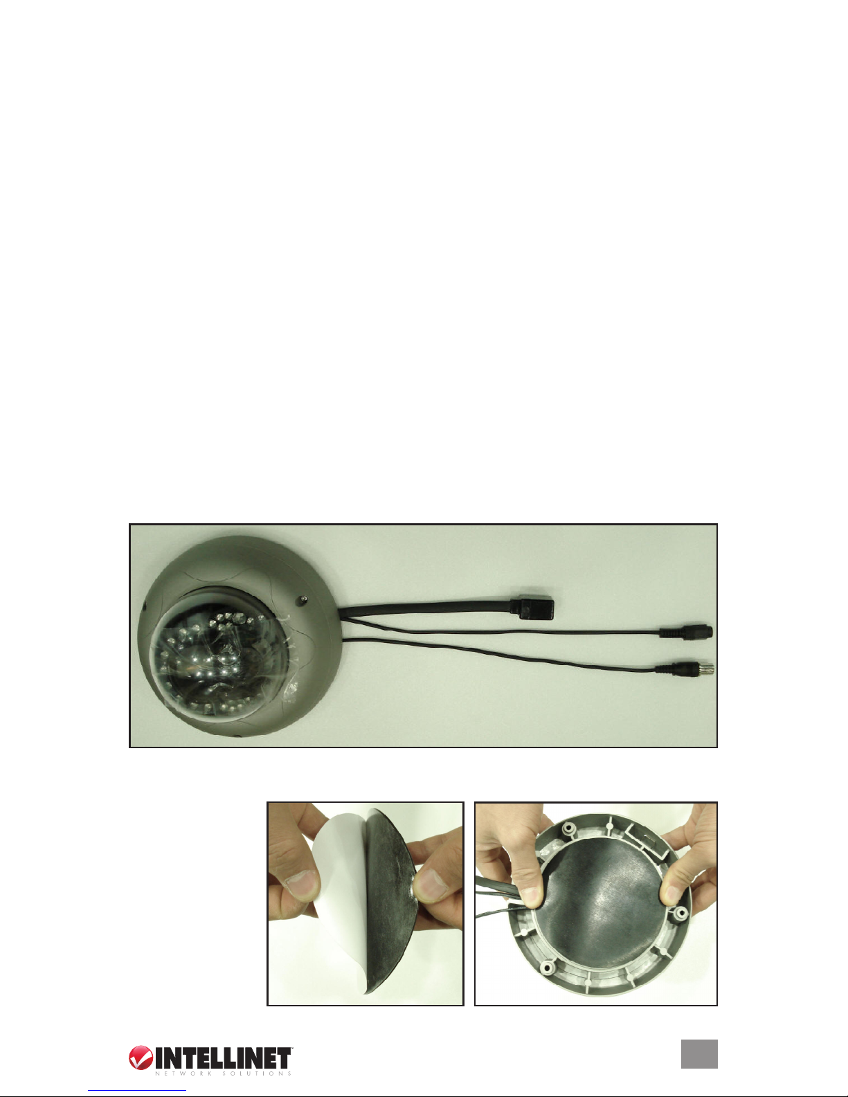
1. Arrange the unit on a at working surface with the power, Ethernet and BNC cables/
connectors spread away from the housing (as shown below).
2. If you’re mounting the camera directly to a at surface (without the use of a bracket), peel
off the protective paper covering and afx the round adhesive rubber plate to the underside
of the housing’s
rear plate. Note
the position of the
three connected
cables (leading
out and away from
the housing).
BNC
RJ-45 for Ethernet
Power
‡
3
Page 4
4
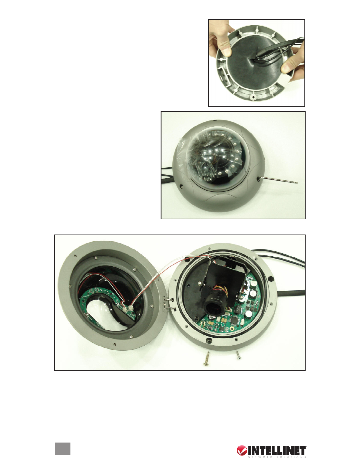
If you’re mounting the camera with a bracket (and not
directly to a at surface), cut an opening in the round
adhesive rubber plate and gently pull the three cables
through (as shown at right) before afxing the rubber
plate to the back of the housing’s rear plate.
3. Using the included “L” wrench,
loosen the screws on the side of the
camera cover (main housing ring)
and carefully separate it (with the
clear dome still in place) from the
rear plate. NOTE: Don’t remove the
protective layer of vinyl from the
clear dome until the installation of
the unit is complete. Also, store the
loose screws in a safe place until
you’re ready to reconnect the two
housing sections.
4. Position the camera on the rear housing plate and x it in place.
5. Attach the housing’s rear plate to the ceiling (or other at surface) using the included screws.
NOTE: For installation with a bracket, separate screws are included in the bracket package.
6. With the camera mounted securely in place, connect the power and Ethernet to the camera.
‡
‡
Screws for ceiling attachment
Screws for housing connection
Page 5
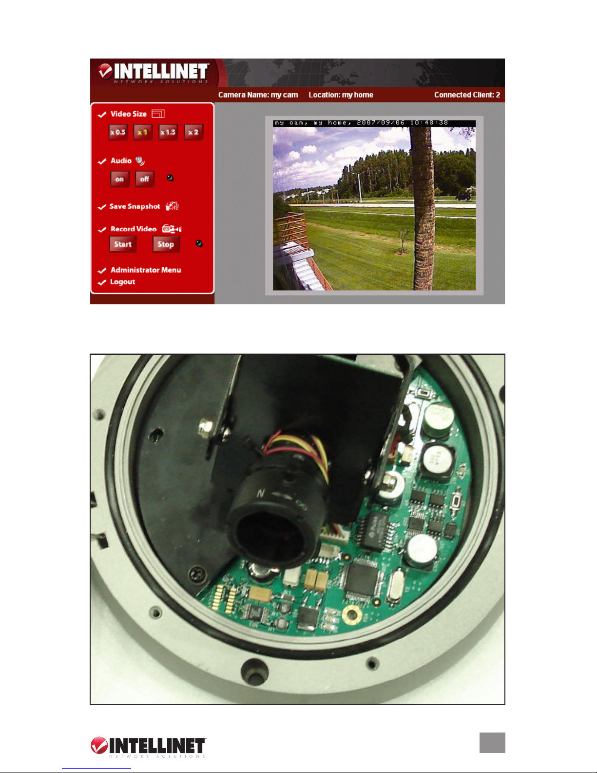
7. Referring to the user manual as needed, obtain an initial view through the camera on your
computer’s browser.
8. For the best picture, loosen the set screw on the lens (recessed in the side of the lens, as
indicated below) and adjust the picture focus by turning the lens clockwise or counterclockwise.
Once you’re satised with the picture focus, tighten the set screw.
‡
5
Page 6
6
9. Re-attach the camera cover (main housing ring) to the mounted rear plate, and remove the
protective outer layer of vinyl from the clear dome.
two-way auDio & Digital iNPut/outPut
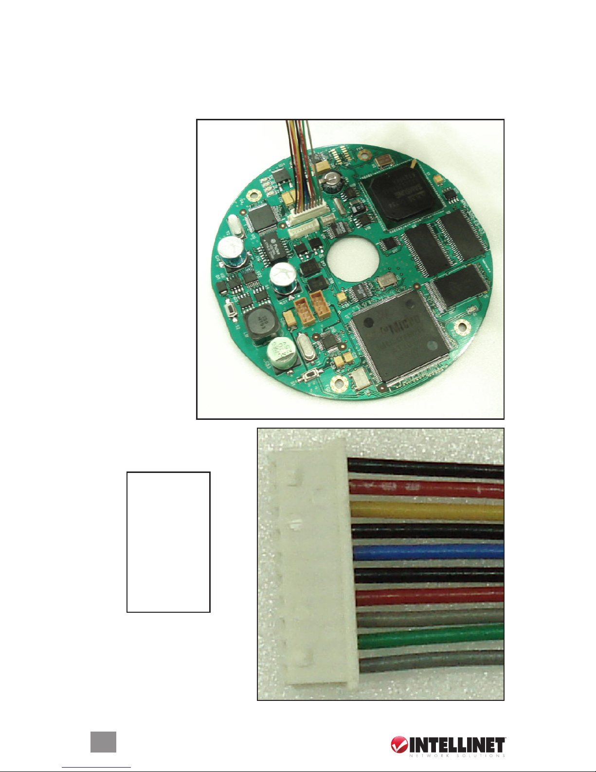
This Pro Series Network Dome Camera supports two-way audio and features digital input (DI)
and digital output (DO) as well as DC power out. To take advantage of this, follow these steps:
1. Attach the supplied
connector to the
network board, as
shown.
2. To the other end of the connector,
attach audio, DI or DO cables
based on the pin chart below.
‡
1 Ground
2 DC 12 V+
3 DO (+)
4 Ground
5 DI (+)
6 Ground
7 Audio In
8 Ground
9 Speaker Out
10 Ground
1
2
3
4
5
6
7
8
9
10
Page 7

Page 8

INTELLINET NETWORK SOLUTIONS™ offers a complete line
of active and passive networking products.
Ask your local computer dealer for more information or visit
www.intellinet-network.com.
Copyright © INTELLINET NETWORK
SOLUTIONS
All products mentioned are trademarks or registered trademarks of their respective owners.
 Loading...