

Page 1
Wireless Access Point
Management Controller
User Manual
M o d e l 5 2 5 74 9 (IW-CNT200
)
intellinetnetwork.com
Important: Read before use. • Importante: Leer antes de usar.
Page 2

Wireless Access Point Management Controller
User Manual
CONTENTS
Product Introduction ...................................................................................................................................................... 3
Product Overview ........................................................................................................................................................... 3
Features ..........................................................................................................................................................................3
Package Contents ......................................................................................................................................................... 3
Hardware Connection ................................................................................................................................................... 3
LED Indicator ................................................................................................................................................................... 3
Front Panel ...................................................................................................................................................................... 3
Rear Panel....................................................................................................................................................................... 4
Installation ...................................................................................................................................................................... 4
Set up By Computer ....................................................................................................................................................... 5
Configure PC via Router ................................................................................................................................................ 5
Logon Screen .................................................................................................................................................................6
Common WEB Configuration Page Buttons and Operations ...................................................................................... 7
Function Configuration .................................................................................................................................................. 7
System Status .................................................................................................................................................................. 7
Network Traffic ................................................................................................................................................................ 8
AP Manage .................................................................................................................................................................... 8
Basic ................................................................................................................................................................................ 8
AP Management ............................................................................................................................................................ 8
Firmware List ....................................................................................................................................................................9
Template ......................................................................................................................................................................... 9
AP Stations .................................................................................................................................................................... 10
Access Control ............................................................................................................................................................. 10
LAN Setup ..................................................................................................................................................................... 10
LAN IP settings .............................................................................................................................................................. 10
USB Application ............................................................................................................................................................ 11
Common Setting .......................................................................................................................................................... 11
Network Neighborhood Share..................................................................................................................................... 12
FTP Share ....................................................................................................................................................................... 12
Administration ..............................................................................................................................................................12
System ........................................................................................................................................................................... 12
Services ......................................................................................................................................................................... 13
Operation Mode ..........................................................................................................................................................13
Firmware Upgrade ........................................................................................................................................................ 14
Settings ......................................................................................................................................................................... 14
Console ......................................................................................................................................................................... 15
Network Information ..................................................................................................................................................... 15
LAN1- 4 ........................................................................................................................................................................... 15
System Log .................................................................................................................................................................... 16
General Log .................................................................................................................................................................. 16
Connection .................................................................................................................................................................. 16
Logout ........................................................................................................................................................................... 16
Appendix: Technical Specifications ............................................................................................................................ 17
Additional Information ................................................................................................................................................. 18
2
Page 3
Wireless Access Point Management Controller
Product Introduction
This User Manual is for the Intellinet Network Solutions Wireless Access Point Management Controller & 5-Port Gigabit
Router. Please read this entire manual before setting up this product and save it for future reference.
Product Overview
This Wireless Access Point Management Controller has an integrated Gigabit router and is the ideal solution for medium to largesized managed wireless installations. It is easy to install and simple to set up. Its offers unified management, seamless roaming
and high-speed, stable wireless network coverage for commercial locations, hotels and other enterprises.
Features
• 1 x 10/100/1000 Mbps RJ45 WAN port, 4 x 10/100/1000 Mbps RJ45 LAN ports
• LEDs to show port status
• Standard 19 rackmount chassis
• Web Management GUI
Package Contents
Before installing the Wireless Access Point Management controller, ensure that the following items have
been included. If any part is missing or damaged, contact your place of purchase.
• Wireless Access Point Management Controller
• Power cable
• User manual
• 19” rackmount brackets
Hardware Connection
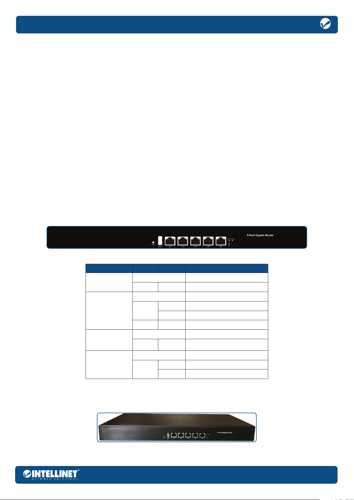
LED Indicator
The LED Indicators on the front panel show the status of the Router.
LED Color Status Indication
PWR
(Power)
WAN LAN1-4
SYS
(System indicator)
USB 2.0
(Interface indicator)
Off Power Off
Green On Power On
Off No device connected.
Green
Yellow On The port is connected at 1000 Mbps.
Off System not started.
Green Blinking
Off No device connected.
Green
Figure 1: front panel
On The port is connected.
Blinking Transmitting or receiving data.
System is starting or the system
started successfully.
On The port is connected.
Blinking Transmitting or receiving data.
Front Panel
The front panel of the Router consists of one reset button, one USB 2.0 port, one WAN port, four LAN ports and a series of LED indicators. Shown as below.
Figure 2: front panel
3
Page 4
Wireless Access Point Management Controller
Reset Button (Reset):
To restore the system to its factory default settings, press and hold the Reset button for 6 seconds when the router is on.
USB 2.0 Port:
Upload and download files from a USB storage device by connecting it to the USB 2.0 storage interface port.
WAN RJ45 Port:
Connect to Cable Internet, xDSL Modem or other LAN through this 10/100/1000 Mbps RJ45 port.
LAN1 – 4 RJ45 Ports:
Four standard 10/100/1000 LAN prots.
LED indicators:
The LED indicators allow you to monitor, diagnose and troubleshoot any potential problem with the Router, connection or attached devices.
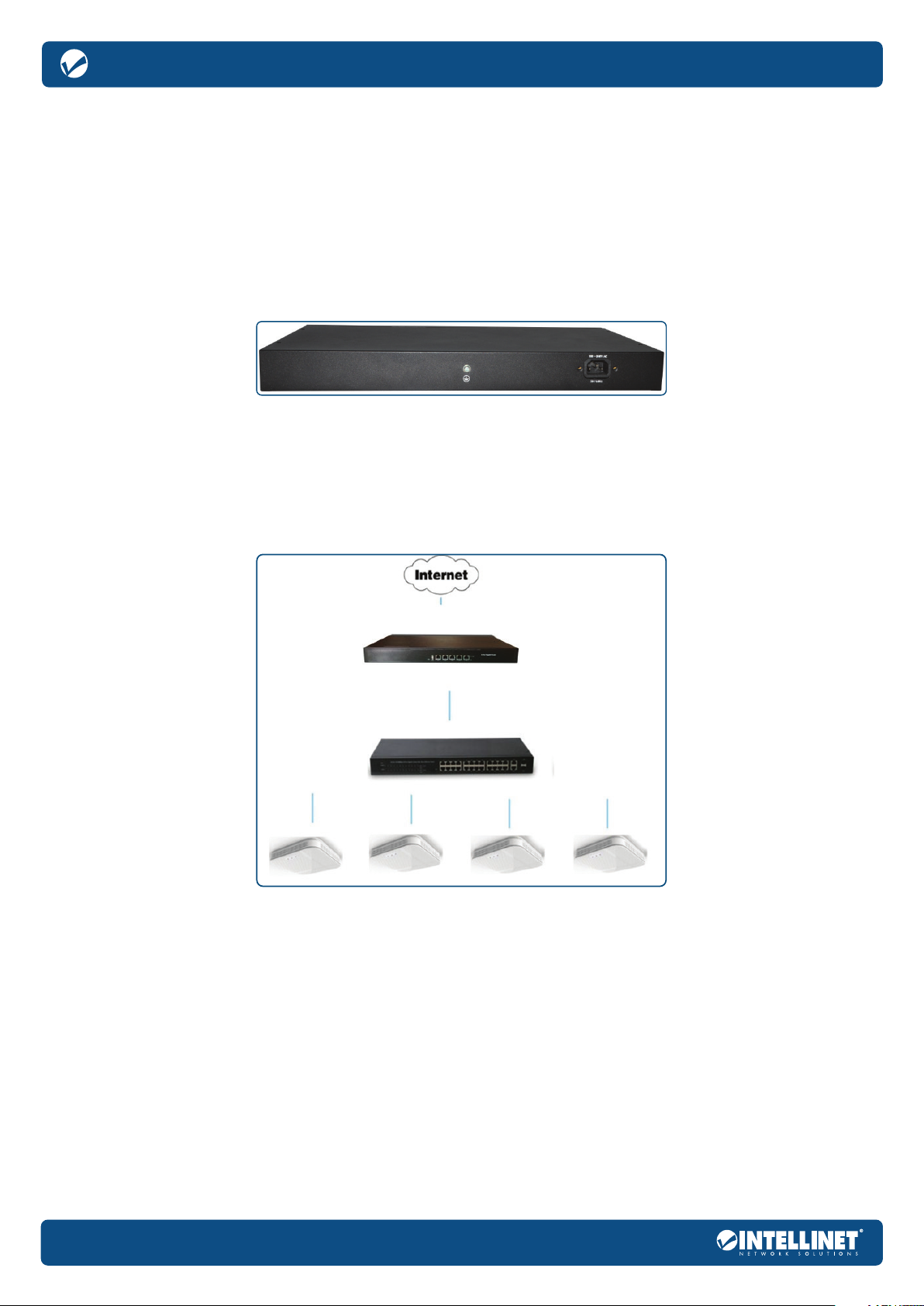
Rear Panel
The rear panel of the Wireless Access Point Management Controller includes one grounding terminal and a power inlet.
User Manual
Grounding Terminal:
Located on the left side of the power supply connector, wire this terminal to a grounding object for lightning protection and power surges.
AC Power Connector
Power is supplied through an external AC power adapter. It supports 100 – 240 V AC, 50/60 Hz.
:
Figure 3: rear panel
Installation
An example network topology is shown below.
4
Figure 4: Installation topology
Page 5
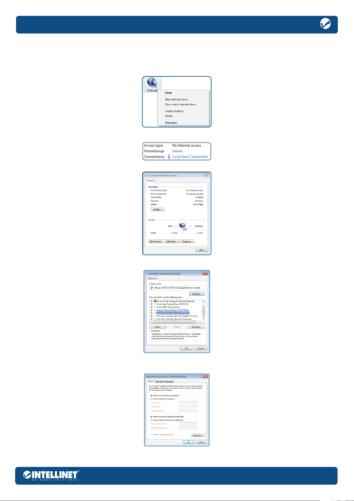
Set up By Computer
Configure PC via Router
1 On your computer desktop, right click on Network and select Properties.
2 Click on Local Area Connection.
3 Click on Properties.
Wireless Access Point Management Controller
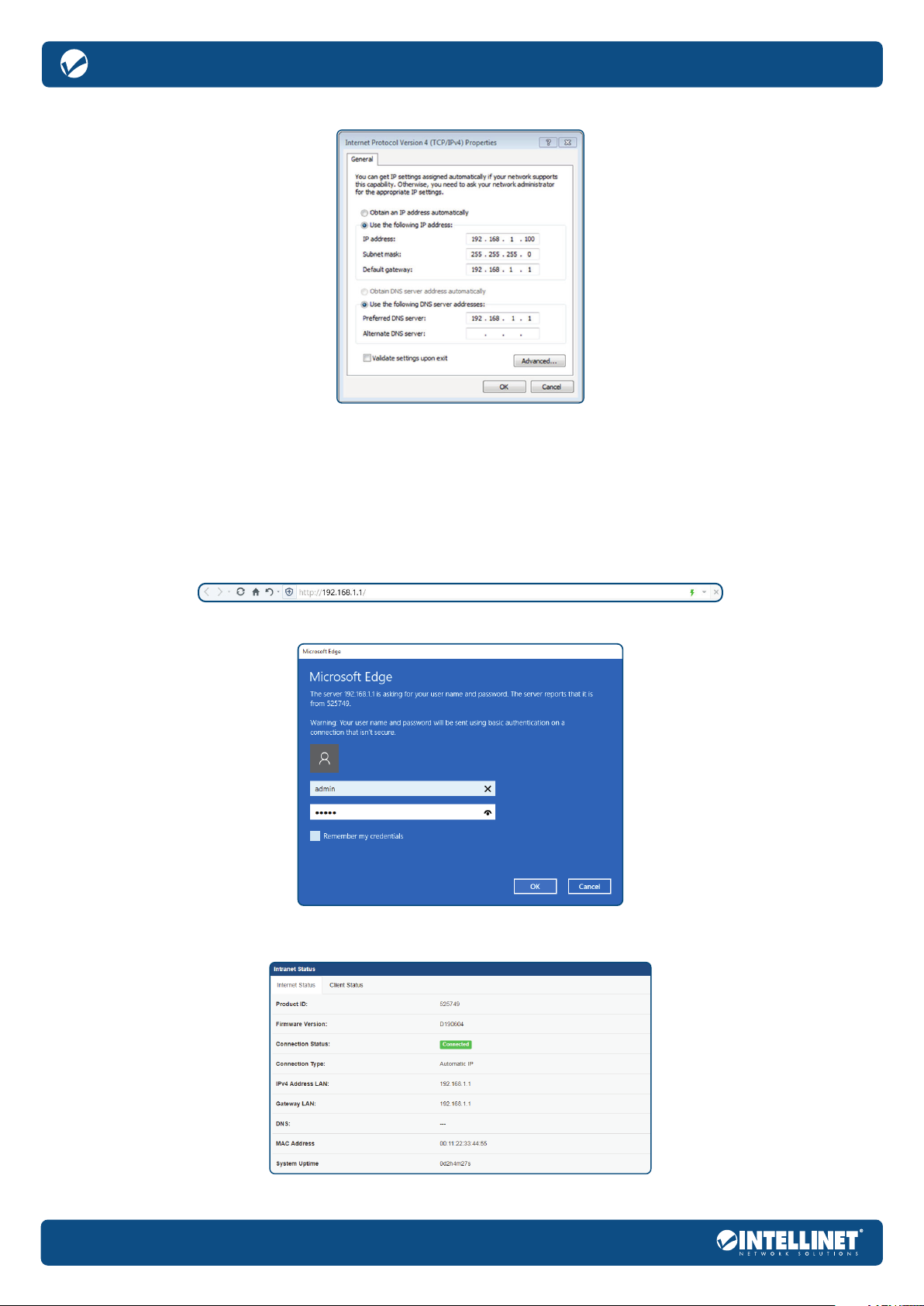
4 Select Internet Protocol Version 4 (TCP/IPv4). Then click Properties.
5 Choose to obtain an IP address automatically or manually set your IP address using the “use the following IP
address” option. Then, choose to automatically assign a DNS server or to set it manually:
5
Page 6
Wireless Access Point Management Controller
Use the following IP address.
IP address: 192.168.1.XXX: (XXX is a number from 2 – 254)
Subnet Mask: 255.255.255.0
Default Gateway: 192.168.1.1
DNS Server: input the DNS server address provided by your ISP; otherwise, use the router default
gateway as the DNS proxy server; click OK to save the configurations.
NOTE: If the DNS server address is unknown, it is recommended to choose “Obtain an IP address automatically”
Click OK to save the setting.
User Manual
Logon Screen
1 Open a browser window and enter http://192.168.1.1 in the address bar.
2 The username is admin. The password is admin. Click OK. The login page follows, as shown:
3 Completing the above steps logs into the Router management interface. Click the menu on the left
side of the home page to go to the corresponding configuration sub-page.
6
Page 7

Common WEB Configuration Page Buttons and Operations
Button Meaning
Save current configuration information
Save current configuration information
Router reboot
Restore factory settings
Upload file
Clear current configuration information
Refresh the content of the list
Select file
Commit NVRAM content to flash memory now
Wireless Access Point Management Controller
Function Configuration
System Status
Click the System Status option to see the following interface:
This System Status interface shows an overview of the Connection Control, Ethernet Link State, Connection
Status, Connection Type, IPv4 Address WAN, Gateway WAN, DNS and MAC Address.
This Client Status interface shows IP and MAC address information of the current connection terminal; screen or cancel the terminal connection here.
7
Page 8

Wireless Access Point Management Controller
Network Traffic
Click the Network Traffic option to see the following interfaces.
This screen shows a router port’s real-time traffic connection.
User Manual
View up to the last 24 hours of port traffic connections speeds here.
AP Manage
Basic
Click AP administration > AC infrastructure option to see the following interface.
Here you can enable or disable the AC.
AP Management
Click AP Management for the following interface:
8
Page 9

Wireless Access Point Management Controller
Choose to refresh an AP, upgrade, restart, reset, configure, delete operations, view AP details, and input a device ID to search for an AP.
Refresh: Refresh the content of the list.
Upgrade: First, configure a corresponding version of the firmware template in the list of firmware
templates, and select the AP that needs an upgrade with the check box on the left.
Reboot: Select the AP that needs restarted by checking the box on the left.
Reset: Select the AP that needs resetting by checking the box on the left.
Configure: First, create a new template in the list of configuration templates, and then select the AP to be configured with the check box on the left.
Delete: Note that the premise of deleting the AP is that the AP is offline. Select the AP(s) to be deleted by checking the box(es) on the left.
Firmware List
Click Firmware List for the following interface.
Create, delete, modify, and query firmware templates.
Refresh: Refresh the content of the list.
Create new template: Select the corresponding AP model, fill in the version and notes of the AP, and choose Save or Restore
(Select Save: the AP information configured remains the same after configuration. Select Restore: the AP information configured
will revert to factory settings after configuration). Then select the firmware to update and click upload, then save.
Delete: Select the firmware template to delete by checking the check box on the left for deletion.
Modify: Select the firmware template to be modified by checking the box to the left, modify its remarks,
modify the saved / restored state, re-upload new firmware and other operations.
Query: Enter the correct hardware model, then click the query, and the list will only display the firmware template information you are querying.
Template
Click Template for the following interface:
9
Page 10

Wireless Access Point Management Controller
Create and delete template information.
Create new template: Fill in new template information such as the template name, support for 5G, mode selection,
AP login account and password, 2.4G and 5G wireless name, password, channel and standby.
Delete: Select the template to delete by checking the check box on the left.
User Manual
AP Stations
Click AP Stations for the following interface:
This interface shows the MAC address of the user, the TX, RX, signal strength, and the MAC address of the the client connected to the AP.
When there are more APs, complete a query by typing the AP’s MAC address in the search box. The list displays all connected user information for the AP.
Access Control
Click Access Control for the following interface:
Add, delete, and modify the client to be filtered.
Add: Fill in the correct MAC address and remarks for the client.
Delete: Select the filter user to delete by checking the check box on the left.
MAC Filter Mode: Select disabled clients in the following list that will not be filtered.
Select a blacklist and the client in the list that will not be able to access the network.
Select the whitelist, and only the clients in the list can access the network.
Modify: Select the client that needs to be modified; edit the client’s MAC address and make remarks.
LAN Setup
LAN IP settings
Click LAN Setup>LAN IP settings.
Configure the LAN IP of the Router. The DHCP Server dynamically changes the IP pool when the LAN IP is changed.
10
Page 11

Wireless Access Point Management Controller
Get IP Automatically: option to have the DHCP server administer and assign IP addresses for LAN clients automatically
IP Address: the LAN IP address of Router; the default is 192.168.1.1.
Subnet Mask: the LAN subnet mask of Router; the default is 255.255.255.0.
Default Gateway: the valid time of obtaining dynamic IP addresses
Domain Name: the Domain Name for clients who request an IP Address from the DHCP Server; the
domain name can only contain alpha-numeric characters and the dash symbol
Get the DNS Server Address Automatically: option to get the DNS IP Address from the remote automatically
DNS Server 1-2: indicates the IP Address of DNS to provide to clients that request an IP Address from the
DHCP server; a blank field means the DNS request will be processed by the Router
Click Apply to save settings.
USB Application
Common Setting
Click USB Application>Common Setting.
This interface shows common settings for the USB Disk and applications:
Click Apply to save settings.
11
Page 12

Wireless Access Point Management Controller
User Manual
Network Neighborhood Share
Click USB Application>Network Neighborhood Share
On the left side of the interface are options to add, delete and modify the account. On the right side of the interface are options to add, delete and
modify the files on the USB storage device inserted into the Router. The Router also provides a graphical list to facilitate file information retrieval.
Click Apply to save settings.
FTP Share
Click USB Application>FTP Share for the following interface:
On the left side of the interface are options to add, delete and modify the account. On the right side of the interface are options to add, delete and
modify the files on the USB storage device inserted into the Router. The Router also provides a graphical list to facilitate file information retrieval.
Click Apply to save settings.
Administration
System
Click Administration>System
Base administration control for the system:
12
Page 13

Wireless Access Point Management Controller
Device Name: the name of the Router
Administrator Login: sets up administrator login
New Password: password cannot be greater than 32 characters
Retype New Password: enter the new password again
Time Zone: the standard time in your area or location
NTP Synchronization Period: selects the NTP synchronization period in the dropdown menu
NTP Server 1-2: synchronizes your system time with NTP server
Remote Log Server: allows a remote server (IPv4 address: port) to assign and record log messages of the Router
Enable Syslog Floating Toolbar?: selecting “yes(*)” enables the function.
Select Web UI Language: selects the language of the Web UI
Enable Context Help: enables context help
Click Apply to save settings.
Services
Click Administration>Services
Base administration control for the Services.
Web Server Protocol: selects the Web server protocol in the dropdown menu
Port of Web Access from LAN: the port of web access from LAN (80 – 65535)
Restricting Web Access from LAN: selecting “yes” enables the function
Enable Telnet Server: selecting ON enables the function
Enable SSH Server: selecting “yes” enables the function
Click Apply to save settings.
Operation Mode
Click Administration>Operation Mode
The Router connects to the Internet via IPoE/PPPoE/PPTP/L2TP protocol and provides Internet sharing for Wired/
Wireless clients. In this mode, NAT, Firewall, UPnP, DHCP Server are available and enabled by default.
Click Apply to save settings.
13
Page 14

Wireless Access Point Management Controller
User Manual
Firmware Upgrade
Click Administration>Firmware Upgrade
Follow the instructions listed below:
1 Check if any new version of firmware is available on the custom firmware website.
2 Download a proper version locally.
3 Specify the path and name of the downloaded file in the [New Firmware File].
4 Click [Upload] to upload the file to router. The upload process may take up to three minutes.
5 After receiving a correct firmware file, the router will automatically start the upgrade process. The system reboots after the upgrading process is finished.
NOTE: For a configuration parameter that exists in both the old and new firmware, its setting will be kept during the upgrade process.
In case the upgrade process fails, the router enters emergency mode automatically. The LED signals at the front
panel will indicate this situation. Use the Firmware Restoration utility to do system recovery.
Click Apply to save settings.
Settings
Click Administration>Settings
This function saves the current router settings to a file or loads settings from a file.
Router reboot: [Reboot] restarts the router.
Factory Default: [Reset] restores the router to its factory default settings and deletes all the current settings; wait for the router to reboot.
Save Setting to a File: [Save] to save current router setting into a file.
Restore Settings from a File: specify the path and name of setting file, then click [Upload] to write the file to router; wait for the router to reboot.
AP Management Database > Factory Default: [Reset] to clear current AP settings and restore the AP to its factory settings; the AP will automatically restart.
Click Apply to save settings.
14
Page 15

Wireless Access Point Management Controller
Console
Click Administration>Console
WARNING! Console emulator may be used only for commands which return results immediately.
Commands such as [top], [ping], [traceroute], etc. will block the Web UI:
Network Information
Click Network Information for the following interface:
LAN1- 4
Click Network Information>LAN1-4 for the following interface:
15
Page 16

Wireless Access Point Management Controller
System Log
General Log
Click System Log>General Log for the following interface:
Connection
User Manual
Click System Log>Connection for the following interface:
Logout
Click Logout to log out.
16
Page 17

Appendix: Technical Specifications
Hardware Specification
CPU Frequency 880 MHz
RAM capacity 256 MB (DDR3)
ROM capacity 16 MB (SPI Flash)
Standards and Protocols IEEE802.3i, IEEE802.3u, IEEE802.3ab
Interfaces
Button Reset Button
Indicators
Power Supply 100 – 240 VAC,50/60 Hz, 5 V / 2 A, internal power
Dimensions (W x D x H) 440*208*44 mm
Environment
Per Device Power LED, SYS LED, USB 2.0 LED
Per Port Link/Activity
1*10/100/1000 Mbps WAN Port (RJ45)
4*10/100/1000 Mbps LAN Port (RJ45)
1*USB 2.0 Host Port
Operating temperature: 0 – 40°C
Storage temperature: -40 – 70°C
Operating humidity: 10 – 90% non-condensing
Storage humidity: 5 – 90% non-condensing
Wireless Access Point Management Controller
Software Specification
Practical Function
• QoS
• DDNS
• The TFTP server
• UPNP
• Scheduled tasks
• Access control
• MAC filter
Security Settings
• Administrator
• LAN WEB management
• Remote WEB management
AC Management
• Status
• AP Management
• Portal
• System Management
Network Settings
WAN connection types supported
PPPoE, DHCP, Static IP, PPtP, L2TP
• The MAC address clone and modify
• Static routing and routing table
• Diagnostics
• Hostname
DHCP Settings
• DHCP Server
• DHCP Client
• The Client List
• Static IP
System Configuration
• Software upgrade
• Save & reload settings
• System log
• NTP server
• Language & Style
• SSH access
Firewall
• DMZ
• Port Forward
17
Page 18

Additional Information
WASTE ELECTRICAL & ELECTRONIC EQUIPMENT
DISPOSAL OF ELECTRIC AND ELECTRONIC EQUIPMENT
(Applicable In The European Union And Other European Countries With Separate Collection Systems)
ENGLISH: This symbol on the product or its packaging
means that this product must not be treated as
unsorted household waste. In accordance with
EU Directive 2012/19/EU on Waste Electrical and
Electronic Equipment (WEEE), this electrical product
must be disposed of in accordance with the user’s local
regulations for electrical or electronic waste. Please
dispose of this product by returning it to your local point
of sale or recycling pickup point in your municipality.
DEUTSCH: Dieses auf dem Produkt oder der Verpackung
angebrachte Symbol zeigt an, dass dieses Produkt
nicht mit dem Hausmüll entsorgtwerden darf. In
Übereinstimmung mit der Richtlinie 2012/19/EU des
Europäischen Parlaments und des Rates über Elektround Elektronik-Altgeräte (WEEE) darf dieses Elektrogerät
nicht im normalen Hausmüll oder dem Gelben Sack
entsorgt werden. Wenn Sie dieses Produkt entsorgen
möchten, bringen Sie es bitte zur Verkaufsstelle zurück
oder zum Recycling-Sammelpunkt Ihrer Gemeinde.
ESPAÑOL: Este símbolo en el producto o su
embalaje indica que el producto no debe tratarse
como residuo doméstico. De conformidad con
la Directiva 2012/19/EU de la UE sobre residuos
de aparatos eléctricos y electrónicos (RAEE), este
producto eléctrico no puede desecharse se con el
resto de residuos no clasificados. Deshágase de este
producto devolviéndolo a su punto de venta o a un
punto de recolección municipal para su reciclaje.
FRANÇAIS: Ce symbole sur Ie produit ou son
emballage signifie que ce produit ne doit pas être
traité comme un déchet ménager. Conformément à la
Directive 2012/19/EU sur les déchets d’équipements
électriques et électroniques (DEEE), ce produit
électrique ne doit en aucun cas être mis au rebut
sous forme de déchet municipal non trié. Veuillez
vous débarrasser de ce produit en Ie renvoyant à
son point de vente ou au point de ramassage local
dans votre municipalité, à des fins de recyclage.
POLSKI: Jeśli na produkcie lub jego opakowaniu
umieszczono ten symbol, wówczas w czasie
utylizacji nie wolno wyrzucać tego produktu wraz
z odpadami komunalnymi. Zgodnie z Dyrektywą
Nr 2012/19/EU w sprawie zużytego sprzętu
elektrycznego i elektronicznego (WEEE), niniejszego
produktu elektrycznego nie wolno usuwać jako
nie posortowanego odpadu komunalnego.
Prosimy o usuniecie niniejszego produktu poprzez
jego zwrot do punktu zakupu lub oddanie do
miejscowego komunalnego punktu zbiórki
odpadów przeznaczonych do recyklingu.
ITALIANO: Questo simbolo sui prodotto o sulla relativa
confezione indica che il prodotto non va trattato
come un rifiuto domestico. In ottemperanza alla
Direttiva UE 2012/19/EU sui rifiuti di apparecchiature
elettriche ed elettroniche (RAEE), questa prodotto
elettrico non deve essere smaltito come rifiuto
municipale misto. Si prega di smaltire il prodotto
riportandolo al punto vendita o al punto di raccolta
municipale locale per un opportuno riciclaggio.
WARRANTY INFORMATION • GARANTIEINFORMATIONEN • GARANTÍA • GARANTIE • GWARANCJI • GARANZIA
USA & CANADA: intellinetsolutions.us
DEUTSCHLAND: intellinetnetwork.de
EN MÉXICO: intellinetsolutions.mx | Póliza de Garantía Intellinet — Datos del importador y responsable
ante el consumidor IC Intracom México, S.A.P.I. de C.V. • Av. Interceptor Poniente # 73, Col. Parque
Industrial La Joya, Cuautitlán Izcalli, Estado de México, C.P. 54730, México. • Tel. (55)1500-4500
La presente garantía cubre los siguientes productos contra cualquier
defecto de fabricación en sus materiales y mano de obra.
A Garantizamos los productos de limpieza, aire comprimido y consumibles, por 60
dias a partir de la fecha de entrega, o por el tiempo en que se agote totalmente
su contenido por su propia función de uso, lo que suceda primero.
B Garantizamos los productos con partes móviles por 3 años.
C Garantizamos los demás productos por 5 años (productos sin partes móviles), bajo las siguientes condiciones:
1 Todos los productos a que se refiere esta garantía, ampara su
cambio físico, sin ningún cargo para el consumidor.
2 El comercializador no tiene talleres de servicio, debido a que los productos que se garantizan
EUROPA: intellinetnetwork.eu
ITALIA: intellinetnetwork.it
18
Page 19

no cuentan con reparaciones, ni refacciones, ya que su garantía es de cambio físico.
3 La garantía cubre exclusivamente aquellas partes, equipos o sub-ensambles que
hayan sido instaladas de fábrica y no incluye en ningún caso el equipo adicional o
cualesquiera que hayan sido adicionados al mismo por el usuario o distribuidor.
Para hacer efectiva esta garantía bastará con presentar el producto al distribuidor en el domicilio
donde fue adquirido o en el domicilio de IC Intracom México, S.A.P.I. de C.V., junto con los accesorios
contenidos en su empaque, acompañado de su póliza debidamente llenada y sellada por la casa
vendedora (indispensable el sello y fecha de compra) donde lo adquirió, o bien, la factura o ticket de
compra original donde se mencione claramente el modelo, número de serie (cuando aplique) y fecha
de adquisición. Esta garantía no es válida en los siguientes casos: Si el producto se hubiese utilizado en
condiciones distintas a las normales; si el producto no ha sido operado conforme a los instructivos de uso;
o si el producto ha sido alterado o tratado de ser reparado por el consumidor o terceras personas.
REGULATORY STATEMENTS
FCC Class B
This equipment has been tested and found to comply with the limits for a Class B digital device, pursuant to
Part 15 of Federal Communications Commission (FCC) Rules. These limits are designed to provide reasonable
protection against harmful interference in a residential installation. This equipment generates, uses and
can radiate radio frequency energy, and if not installed and used in accordance with the instructions may
cause harmful interference to radio communications. However, there is no guarantee that interference will
not occur in a particular installation. If this equipment does cause harmful interference to radio or television
reception, which can be determined by turning the equipment off and on, the user is encouraged to try to
correct the interference by one or more of the following measures: reorient or relocate the receiving antenna;
increase the separation between the equipment and the receiver; connect the equipment to an outlet on a
circuit different from the receiver; or consult the dealer or an experienced radio/TV technician for help.
CE
ENGLISH: This device complies with the requirements of CE RED 2014/53/EU, 2014/30/EU
and/or 2014/35/EU. The Declaration of Conformity for is available at:
DEUTSCH: Dieses Gerät enspricht der CE RED 2014/53/EU, 2014/30/EU und / oder
2014/35/EU. Die Konformitätserklärung für dieses Produkt finden Sie unter:
ESPAÑOL: Este dispositivo cumple con los requerimientos de CE RED 2014/53/EU,
2014/30/EU y / o 2014/35/EU. La declaración de conformidad esta disponible en:
FRANÇAIS: Cet appareil satisfait aux exigences de CE RED 2014/53/EU, 2014/30/EU
et / ou 2014/35/EU. La Déclaration de Conformité est disponible à :
POLSKI: Urządzenie spełnia wymagania CE RED 2014/53/EU, 2014/30/EU I / lub 2014/35/EU.
Deklaracja zgodności dostępna jest na stronie internetowej producenta:
ITALIANO: Questo dispositivo è conforme alla CE RED 2014/53/EU, 2014/30/EU
e / o 2014/35/EU. La dichiarazione di conformità è disponibile al:
intellinetnetwork.com
North America
IC Intracom America
550 Commerce Blvd.
Oldsmar, FL 34677, USA
Xizhi Dist., New Taipei City 221, Taiwan
Asia & Africa
IC Intracom Asia
4-F, No. 77, Sec. 1, Xintai 5th Rd.
Europe
IC Intracom Europe
Löhbacher Str. 7, D-58553
Halver, Germany
All trademarks and trade names are the property of their respective owners.
Alle Marken und Markennamen sind Eigentum Ihrer jeweiligen Inhaber.
Todas las marcas y nombres comerciales son propiedad de sus respectivos dueños.
Toutes les marques et noms commerciaux sont la propriété de leurs propriétaires respectifs.
Wszystkie znaki towarowe i nazwy handlowe należą do ich właścicieli.
Tutti i marchi registrati e le dominazioni commerciali sono di proprietà dei loro rispettivi proprietari.
19
Page 20

intellinetnetwork.com
All trademarks and trade names are the property of their respective owners.
© IC Intracom. All rights reserved. Intellinet Network Solutions is a
trademark of IC Intracom, registered in the U.S. and other countries.
INT_525749_UM_1219_REV_5.01
 Loading...