

Intellinet 524810 User Manual
WIRELESS
150N PCI
CARD
USER
MANUAL
MODEL 524810
INT-524810-UM-0110-04

2
Thank you for purchasing the INTELLINET NETWORK SOLUTIONS™ Wireless
150N PCI Card, Model 524810.
This compact high-speed adapter allows you to connect your desktop computer to
wireless networks so you can transfer or receive digital images, videos and MP3
les faster than ever, connecting to the wireless network with link speeds of up to
150 Mbps using the latest in wireless technology. This adapter is also compatible
with 802.11b and 802.11g wireless access points and wireless routers, giving you
the exibility to start upgrading your wireless network without the need to replace
your existing equipment.
Detailed instructions in this user manual make installation reasonably quick and
simple so you’ll soon be enjoying the benets of all these additonal features:
• Detachable 3 dBi antenna with reverse SMA connector
• Supports WMM (Wi-Fi Multimedia) for increased multimedia data throughput
• Supports the most popular operating systems: Windows 2000, XP, Vista and 7
• Supports Software AP function (turns your wireless client into a wireless access
point)
• Includes low prole 8 cm bracket
• Three-Year Warranty
System Requirements
• Desktop PC with Pentium 300 MHz-compatible processor or higher
• Windows 2000, XP, 2003, Vista or 7
• Available 32-bit PCI slot
Package Contents
• Wireless 150N PCI Card
• 1 antenna
• Quick install guide
• Low prole 8 cm bracket
• Setup CD with user manual
NOTE: Some screen images have been modied to t the format of this manual.

3
SAFETY & COMPLIANCE STATEMENTS
FCC Part 15
This equipment has been tested and found to comply with the limits for a Class B
digital device, pursuant to Part 15 of Federal Communications Commission (FCC)
Rules. These limits are designed to provide reasonable protection against harmful
interference in a residential installation. This equipment generates, uses and can
radiate radio frequency energy and, if not installed and used in accordance with
the instructions, may cause harmful interference to radio communications. However,
there is no guarantee that interference will not occur in a particular installation. If
this equipment does cause harmful interference to radio or TV reception, which can
be determined by turning the equipment off and on, the user is encouraged to try
to correct the interference by one or more of the following measures:
• Reorient or relocate the receiving antenna.
• Increase the separation between the equipment and the receiver.
• Connect the equipment to an outlet on a circuit different from the receiver.
• Consult the dealer or an experienced radio/TV technician for help.
FCC Caution
This device and its antenna must not be co-located or operated in conjunction with
any other antenna or transmitter.
This device complies with Part 15 of the FCC Rules. Operation is subject to the
following two conditions: (1) this device may not cause harmful interference, and
(2) this device must accept any interference received, including interference that
may cause undesired operation.
Any changes or modications not expressly approved by the party responsible for
compliance could void the authority to operate equipment.
FCC Radiation Exposure Statement
This equipment complies with FCC radiation exposure limits set forth for an
uncontrolled environment. In order to avoid the possibility of exceeding the FCC
radio frequency exposure limits, human proximity to the antenna shall not be less
than 20 cm (8 inches) during normal operation. The equipment version marketed
in the U.S. is restricted to usage of the channels 1-11 only.
R&TTE Compliance Statement
This equipment complies with all the requirements of Directive 1999/5/EC of the
European Parliament and the Council of March 9, 1999, on radio equipment

4
and telecommunication terminal equipment and the mutual recognition of their
conformity (R&TTE). The R&TTE directive repeals and replaces Directive 98/13/
EEC (Telecommunications Terminal Equipment and Satellite Earth Station
Equipment) as of April 8, 2000.
Safety
This equipment is designed with the utmost care for the safety of those who install
and use it. However, special attention must be paid to the dangers of electric shock
and static electricity when working with electrical equipment. All guidelines must
therefore be followed at all times to ensure the safe use of the equipment.
EU Countries Intended for Use
The ETSI version of this device is intended for home and ofce use in Austria,
Belgium, Denmark, Finland, France, Germany, Greece, Ireland, Italy, Luxembourg,
the Netherlands, Portugal, Spain, Sweden and the United Kingdom. The ETSI
version of this device is also authorized for use in EFTA member states Iceland,
Liechtenstein, Norway and Switzerland.
EU Countries Not Intended for Use
None.
Safe Operating Guidelines
• The Wireless 150N PCI Card is designed for indoor use only. Do not expose this
card to direct sunlight, rain or snow.
• Do not place or use this card in or near excessively hot or humid places, such as
kitchens or bathrooms.
• This card can become hot when used for long time. This is normal and is not a
malfunction. Do not place the card on paper, cloth or other ammable materials
after extended use.
• There are no user-serviceable parts inside the card. If the card isn’t working
properly, contact your place of purchase and ask for help. Do not disassemble the
card yourself, as doing so will void the warranty.
• If the card falls into water, do not use it again before it’s inspected by an authorized
technician, as recommended by your place of purchase.
• If strange odors or smoke emanate from the card, immediately switch the
computer off and call your place of purchase for help.

5
CONTENTS
TABLE OF CONTENTS
section page
1 HARDWARE .........................................................................................................................6
1.1 Card Components ..........................................................................................................6
1.2 Installing the Card ..........................................................................................................6
2 DRIVER INSTALLATION ......................................................................................................7
3 CONFIGURATION ..............................................................................................................11
3.1 Network Settings ..........................................................................................................11
3.1.1 INTELLINET Cong Utility .....................................................................................12
3.1.1.1 Scanning for Other Devices ............................................................................12
3.1.1.2 Connecting to an AP .......................................................................................14
3.1.1.3 Adding an AP to Prole List .............................................................................15
3.1.2 Using the WZC Utility ............................................................................................20
3.2 Prole Management .....................................................................................................23
3.2.1 Add a Prole ..........................................................................................................24
3.2.2 Edit an Existing Prole ...........................................................................................24
3.2.3 Delete an Existing Prole .......................................................................................24
3.2.4 Activate a Prole ....................................................................................................24
3.3 Advanced Settings .....................................................................................................24
3.4 View Network Statistics .............................................................................................26
3.5 WMM Settings ...........................................................................................................26
3.6 WPS Conguration ....................................................................................................27
3 .6.1 PBC .......................................................................................................................28
3.6.2 PIN ........................................................................................................................30
3.7 Radio On/Off ..............................................................................................................31
3.8 About ........................................................................................................................31
4 S
oft
AP ........................................................................................................................32
4.1 S
oft
AP Conguration ..................................................................................................32
4.2 Security Settings ......................................................................................................... 34
4.3 Access Control .............................................................................................................36
4.4 Connection Table .........................................................................................................37
4.5 Event Log .....................................................................................................................37
4.6 Statistics ......................................................................................................................38
4.7 About ........................................................................................................................39
5 TROUBLESHOOTING ........................................................................................................40
6 FREQUENTLY ASKED QUESTIONS .................................................................................41
7 SPECIFICATIONS.............................................................................................................. 44
6
HARDWARE
1 HARDWARE
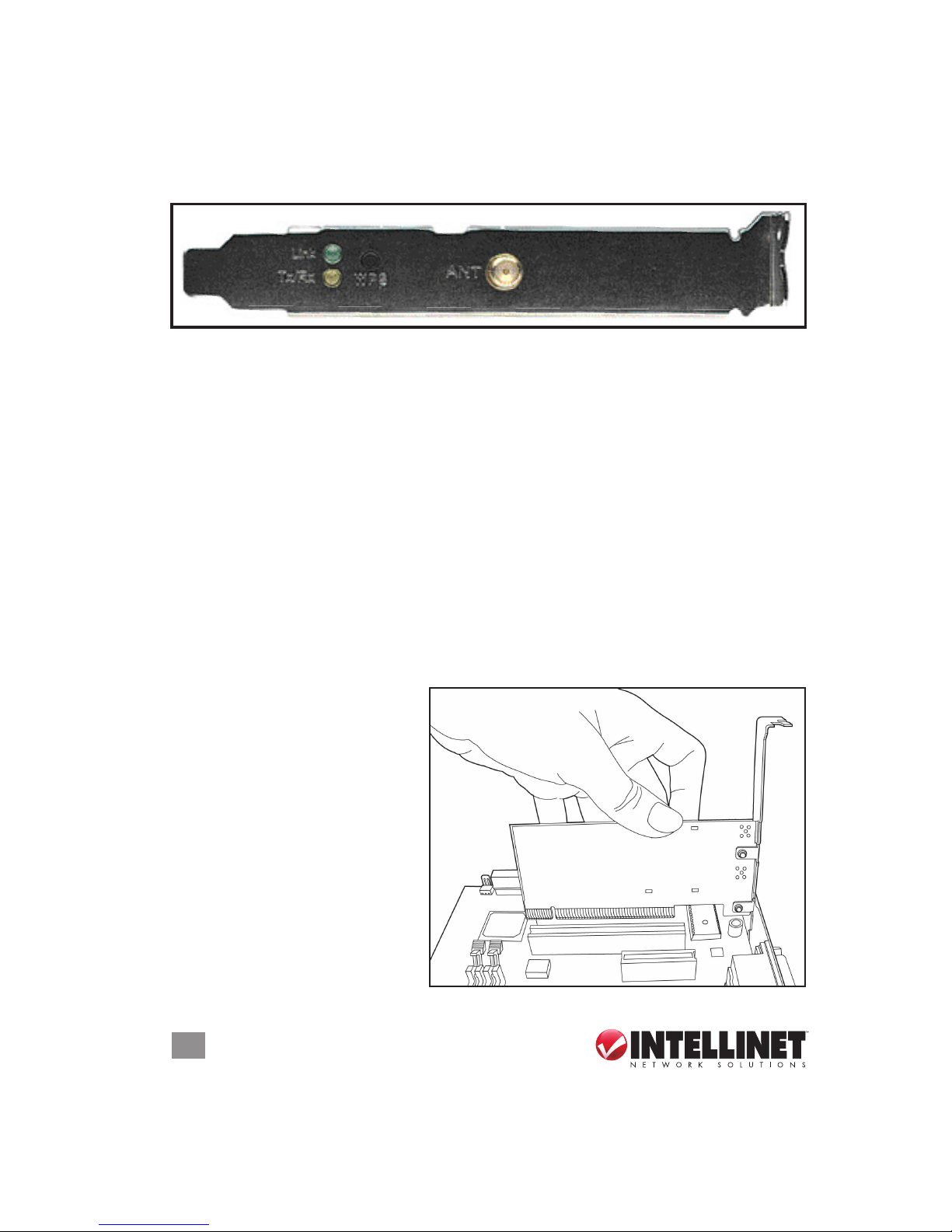
1.1 Card Components
• Screw the included antenna onto the reverse SMA connector after the card has
been installed on the computer (see below). It’s recommended that the antenna
be positioned at a 90˚ angle to the card initially for what is typically the best radio
reception, adjusting it as needed later.
• Press and hold the WPS button for 3 seconds to start the WPS function. When
WPS is enabled, the Link and Tx/Rx LEDs will light.
• The Tx/Rx LED is yellow and blinks when data is being transferred or received.
When it’s off, there is no wireless activity. When WPS is enabled, this LED remains
on.
• The Link LED is green. It lights when a link has been established to a wireless
access point; it goes off when the radio is switched off. When WPS is enabled,
this LED remains on
.
1.2 Installing the Card
1. Turn off the computer.
2. Remove the cover.
3. Insert the card into an empty
PCI slot on the computer.
4. Attach the antenna and
position it as directed above.
5. Replace the cover and turn
the computer on.
ANT
WPS
Tx/Rx
Link
7
DRIVER INSTALLATION
2 DRIVER INSTALLATION
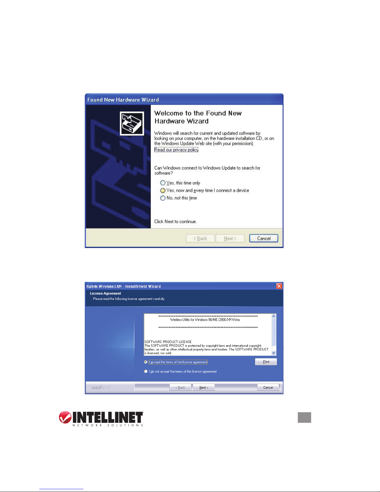
Once the Wireless 150N PCI Card is installed and the computer is turned back on,
the Welcome to the Found New Hardware Wizard screen will display. Click “Cancel”
and proceed with the driver installation procedure below.
1.
Insert the included setup CD and run the Setup.exe program.
2. When the License Agreement screen displays, read the agreement, select “I
accept the terms of the license agreement” and click “Next.”
8
DRIVER INSTALLATION
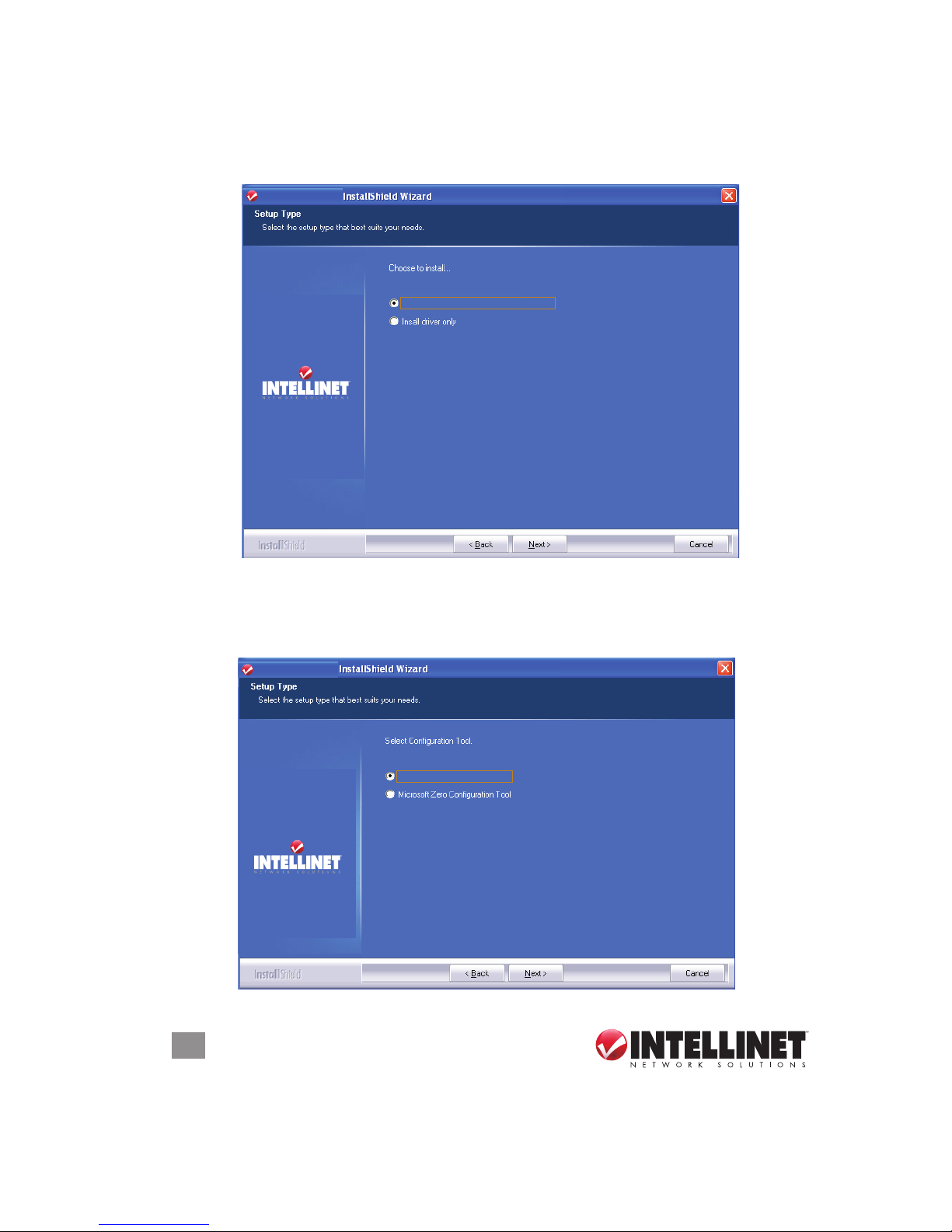
3. It’s recommended that both the driver and utility be installed from the Setup Type
screen if the card is being installed on this computer for the rst time. Select
“Install driver only” if you prefer. Click “Next”to continue.
4. On the second Setup Type screen, it’s recommended that you select “INTELLINET
Conguration Tool,” as it provides full access to all the functions of this card. If
you prefer to use the wireless conguration tool provided by Windows XP or
Vista, select “Microsoft Zero Conguration Tool.” Click “Next.”
INTELLINET
INTELLINET
Install driver and INTELLINET WLAN Utility
INTELLINET
INTELLINET
Install driver and INTELLINET WLAN Utility
INTELLINET
INTELLINET
INTELLINET Confi guration To ol
9
DRIVER INSTALLATION
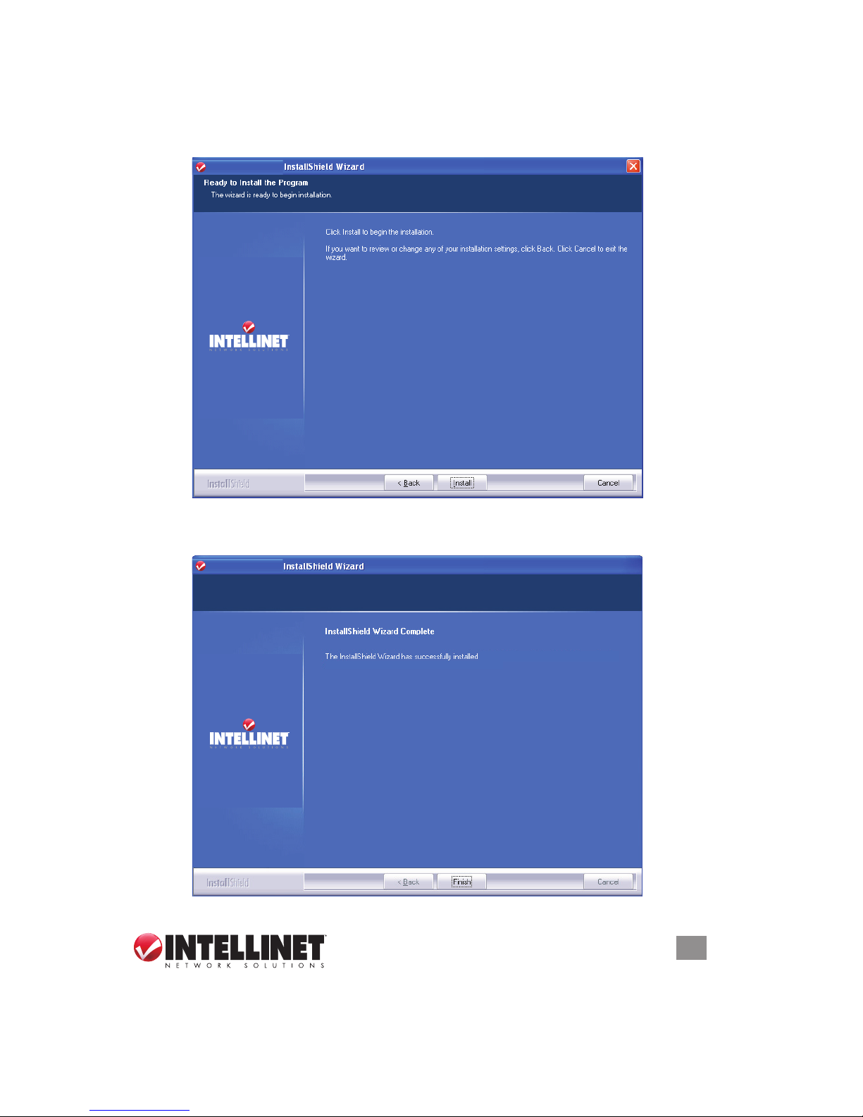
5. When the Ready to Install the Program screen displays, click “Install.” If another
Found New Hardware screen displays instead, wait a moment for the program
to update, then continue. After you click “Install,” wait for the program to run.
6. When the nal utility screen displays, click “Finish” to complete the driver
installation process.
INTELLINET
INTELLINET
INTELLINET
INTELLINET
INTELLINET
INTELLINET
the INTELLINET WLAN Utility. Click Finish
to exit the wizard.
10
DRIVER INSTALLATION
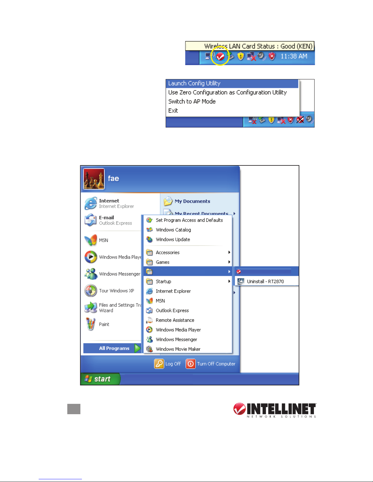
Once installation is complete, the
wireless conguration utility displays
on the computer desktop and as an
INTELLINET icon in the systems tray. Mouse-over the icon to learn the card status.
To congure your wireless
connection, right-click on the
icon to display the popup menu.
Click “Launch Cong Utility” to
start the conguration program.
To close the utility, click “Exit.”
NOTE: If you click “Exit” to close the conguration utility, you won’t be able to
maintain the wireless link to the access point you want to use. In this case, you can
re-launch the utility by going to Start on the desktop and clicking the Wireless
Utility option, as shown below.
INTELLINET Wireless Utility
INTELLINET Wireless
11
CONFIGURATION
3 CONFIGURATION
Once the driver is installed, it will automatically try to connect to any unencrypted
wireless access point. If you want to connect to a specic wireless access point, or
if the access point you want to connect to uses encryption, you need to congure
the Wireless 150N PCI Card and input the required parameters rst.
The current status of your wireless connection is indicated by the appearance of
the conguration utility icon.
The wireless connection is established: good signal reception.
The wireless connection is established: normal signal reception.
The wireless connection is established: weak signal reception.
The connection is not established yet or was lost.
The wireless network card is not detected
.
3.1 Network Settings
Right-click the conguration utility icon on the desktop to display the popup menu;
then click “Launch Cong Utility” (as shown on Page 10). The utility will automatically
begin to scan for all wireless access points and display a Network screen.
As mentioned in Section 2: Driver Installation, there are two ways to congure the
card to connect to a wireless access point: using the INTELLINET conguration
utility and using Windows’ built-in Microsoft Zero Conguration Tool. Both options
are detailed below
.
3 CONFIGURATION
Once the driver is installed, it will automatically try to connect to any unencrypted
wireless access point. If you want to connect to a specifi c wireless access point, or
if the access point you want to connect to uses encryption, you need to confi gure
the Wireless 150N PCI Card and input the required parameters fi rst.
The current status of your wireless connection is indicated by the appearance of
the confi guration utility icon.
The wireless connection is established: good signal reception.
The wireless connection is established: normal signal reception.
The wireless connection is established: weak signal reception.
The connection is not established yet or was lost.
The wireless network card is not detected
.
3.1 Network Settings
Right-click the confi guration utility icon on the desktop to display the popup menu;
then click “Launch Confi g Utility” (as shown on Page 10). The utility will automatically
begin to scan for all wireless access points and display a Network screen.
INTELLINET_UI
INTELLINET_UI
12
CONFIGURATION
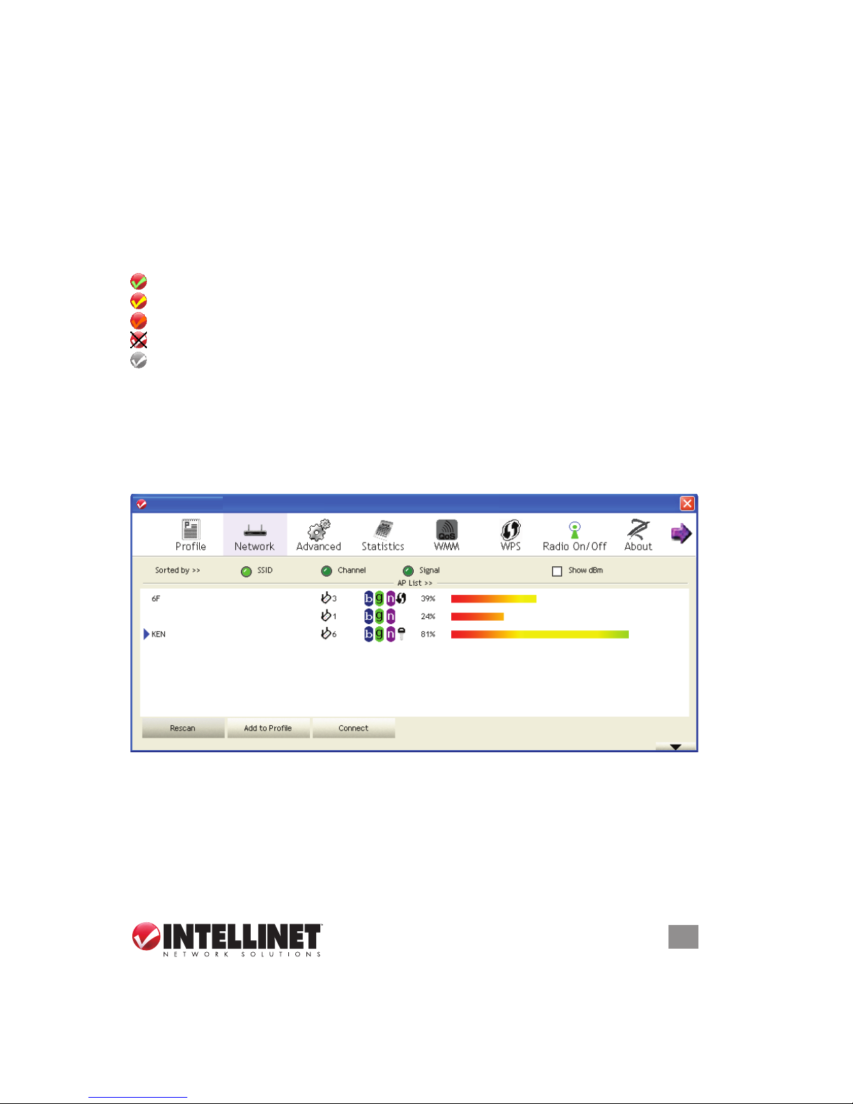
3.1.1 INTELLINET Conguration Utility
All utility screens present a menu of function options — Prole, Network, etc. —
across the top. The Network screens feature a setup window below the menu
section, which expands in depth automatically to accommodate information that
corresponds to the current card activity. TIP: You can also expand the setup window
by clicking the “More/Less” up/down arrow button at the bottom-right of the screen
(clicking it again to revert back to the original window size).
3.1.1.1 Scanning for Other Wireless Devices
There are two kinds of wireless connection mode: Infrastructure and Ad-Hoc.
Infrastructure mode is used by wireless access points, which are able to establish
wireless connections for you and other wireless or wired network clients.
Ad-Hoc mode is also known as Point-to-Point mode. In this mode, wireless devices
such as computers or PDAs will not be capable of establishing wireless connections
with more than one wireless device, and so is suitable for establishing a one-to-one
wireless connection between two wireless devices.
Before you can connect to any wireless access point or device by Infrastructure or
Ad-Hoc mode, there two pieces of information you need to have:
• The wireless device’s SSID, or service set identier (which you can think of as an
access point’s name). You can scan for the SSID of other wireless devices nearby,
but if the SSID of the wireless device you want to connect to is hidden, you need
to know it — exactly — before you can establish a connection with it.
• The wireless device’s encryption key (if it uses encryption).
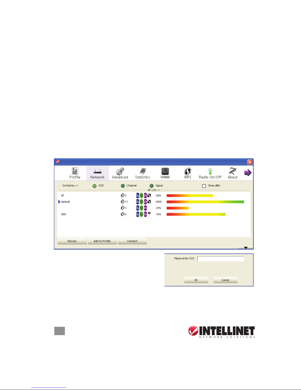
When the scan results are displayed in the setup window, check that the wireless
device (access point or another computer) with the SSID you want to connect to is
included.
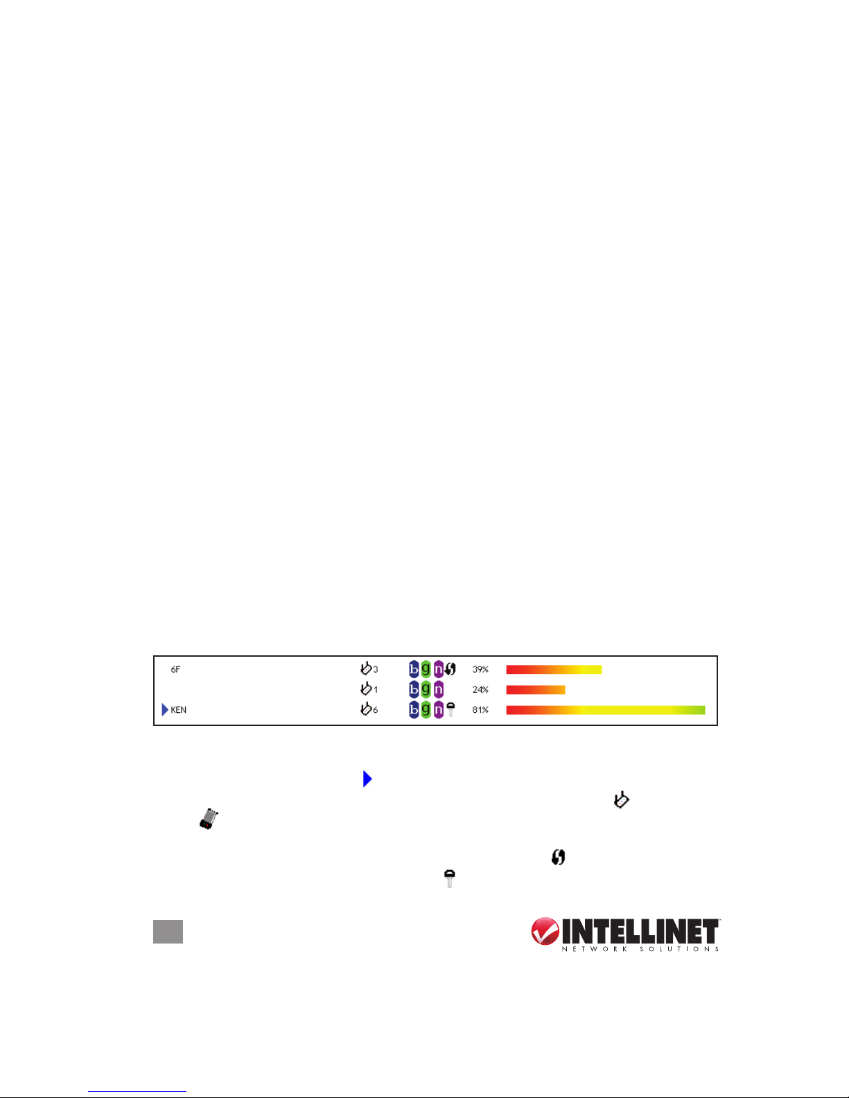
Scan results include several pieces of information:
• The wireless device’s SSID is displayed to the left (KEN, 6F in the example above).
If nothing appears, it means the SSID of that device is hidden. When a connection
is established, a blue arrow ( ) displays to the left of the SSID.
• The type and channel number of the wireless device, depicted by if it’s an AP
or by if it’s a computer (Ad-Hoc mode, point-to-point connection)
• The wireless standard supported by this access point: “n” for 802.11n; “g” for
802.11g; and “b” for 802.11b. Additionally, the WPS icon ( ) will appear when the
access point supports WPS; a key icon ( ) will appear if the access point uses
3.1.1 INTELLINET Confi guration Utility
All utility screens present a menu of function options — Profi le, Network, etc. —
across the top. The Network screens feature a setup window below the menu
section, which expands in depth automatically to accommodate information that
corresponds to the current card activity. TIP: You can also expand the setup window
by clicking the “More/Less” up/down arrow button at the bottom-right of the screen
(clicking it again to revert back to the original window size).
3.1.1.1 Scanning for Other Wireless Devices
There are two kinds of wireless connection mode: Infrastructure and Ad-Hoc.
Infrastructure mode is used by wireless access points, which are able to establish
wireless connections for you and other wireless or wired network clients.
Ad-Hoc mode is also known as Point-to-Point mode. In this mode, wireless devices
such as computers or PDAs will not be capable of establishing wireless connections
with more than one wireless device, and so is suitable for establishing a one-to-one
wireless connection between two wireless devices.
Before you can connect to any wireless access point or device by Infrastructure or
Ad-Hoc mode, there two pieces of information you need to have:
• The wireless device’s SSID, or service set identifi er (which you can think of as an
access point’s name). You can scan for the SSID of other wireless devices nearby,
but if the SSID of the wireless device you want to connect to is hidden, you need
to know it — exactly — before you can establish a connection with it.
• The wireless device’s encryption key (if it uses encryption).
When the scan results are displayed in the setup window, check that the wireless
device (access point or another computer) with the SSID you want to connect to is
included.
Scan results include several pieces of information:

13
CONFIGURATION
encryption. NOTE: When the access point supports WPS and the WPS icon
appears, you won’t see the key icon here even through the access point uses
encryption.
• The signal strength of the access point as a percentage (100% = full strength).
• The signal strength of the access point as a bar graph (as a visual comparison).
If you don’t see the access point you want, click “Rescan” until the AP you prefer is
displayed. If rescanning doesn’t nd the AP you want after ve tries, move your
computer closer to the access point or refer to Section 5: Troubleshooting.
To see detailed information about a specic access point, double-click on it. The
expanded screen presents four more packets of information in addition to the
options and details already displayed.
Sorted by >> — You can sort all listed access points: by SSID, channel or signal
(strength).
Show dBm — Check this box to show the signal strength in decibels instead of as
a percentage.
encryption. NOTE: When the access point supports WPS and the WPS icon
appears, you won’t see the key icon here even through the access point uses
encryption.
• The signal strength of the access point as a percentage (100% = full strength).
• The signal strength of the access point as a bar graph (as a visual comparison).
If you don’t see the access point you want, click “Rescan” until the AP you prefer is
displayed. If rescanning doesn’t fi nd the AP you want after fi ve tries, move your
computer closer to the access point or refer to Section 5: Troubleshooting.
To see detailed information about a specifi c access point, double-click on it. The
expanded screen presents four more packets of information in addition to the
options and details already displayed.
INTELLINET_UI
INTELLINET_UI
14
CONFIGURATION
Rescan — Click to rescan for access points.
Add to Prole — To store a specic access point in the Prole List (see Section 3.1.3:
Add an Access Point to Prole) so that you can link to it directly without entering
the authentication key again, select the AP, then click “Add to Prole.”
Connect — Click to connect to whichever access point is selected on the list.
General —Displays basic information about the selected access point, such as
SSID, MAC address, authentication/encryption type, channel and such.
WPS — If this access point supports WPS (Wi-Fi Protected Setup), related
information is displayed here.
CCX —If this access point supports CCX (Cisco Compatible eXtension), related
information is displayed here.
802.11n — If this access point complies with the 802.11n draft, related information
is displayed here.
3.1.1.2 Connecting to an Access Point
1. Select the wireless access point or network device you want to connect to and
click “Connect.” If the access point you selected doesn’t use encryption, you’ll
be connected to it within a minute. If it does use encryption, go to Step 3.
2. If the wireless access point doesn’t show
an SSID, you’ll be prompted to enter it.
NOTE: If you need to obtain the SSID
from the owner of the wireless access
point you’re connecting to, make sure it’s
exact or the connection won’t work. Once you’ve entered the SSID, click “OK.”
3. If the wireless access point uses encryption, you will be prompted to enter its
WEP key or WPA preshared key. NOTE: If you need to obtain the key from the
owner of the device you’re connecting to, make sure it’s exact or the connection
INTELLINET_UI
INTELLINET_UI
 Loading...