

WIRELESS
150N
PORTABLE
3G ROUTER
USER
MANUAL
MODEL
524803
INT-524803-UM-1009-02

Federal Communications Commission
Interference Statement
FCC Part 15
This equipment has been tested and found to comply with the limits
for a Class B digital device, pursuant to Part 15 of FCC Rules.
These limits are designed to provide reasonable protection against
harmful interference in a residential installation. This equipment
generates, uses and can radiate radio frequency energy and, if not
installed and used in accordance with the instructions, may cause
harmful interference to radio communications. However, there is no
guarantee that interference will not occur in a particular installation.
If this equipment does cause harmful interference to radio or
television reception, which can be determined by turning the
equipment off and on, the user is encouraged to try to correct the
interference by one or more of the following measures:
1. Reorient or relocate the receiving antenna.
2. Increase the separation between the equipment and
receiver.
3. Connect the equipment into an outlet on a circuit different
from that to which the receiver is connected.
4. Consult the dealer or an experienced radio technician for
help.
FCC Caution
This equipment must be installed and operated in accordance with
provided instructions, and a minimum of 20 cm of space (approx. 8
inches) must be provided between any computer-mounted antenna
and a person’s body (excluding hands, wrists and feet) during
wireless modes of operation.
This device complies with Part 15 of the FCC Rules. Operation is
subject to the following two conditions: (1) This device may not

cause harmful interference; and (2) This device must accept any
interference received, including interference that may cause
undesired operation.
Any changes or modifications not expressly approved by the party
responsible for compliance could void the authority to operate the
equipment.
Federal Communications Commission (FCC) Radiation
Exposure Statement
This equipment complies with FCC radiation exposure set forth for
an uncontrolled environment. In order to avoid the possibility of
exceeding the FCC radio frequency exposure limits, human
proximity to the antenna shall not be less than 20 cm (8 inches)
during normal operation.
The antenna(s) used for this transmitter must not be co-located or
operating in conjunction with any other antenna or transmitter.
The equipment version marketed in the U.S. is restricted to usage
of channels 1-11 only.

R&TTE Compliance Statement
This equipment complies with all the requirements of Directive
1999/5/EC of the European Parliament and the Council of March 9,
1999, on radio equipment and telecommunication terminal
equipment and the mutual recognition of their conformity (R&TTE).
The R&TTE Directive repeals and replaces in the directive
98/13/EEC (Telecommunications Terminal Equipment and Satellite
Earth Station Equipment) as of April 8, 2000.
Safety
This equipment is designed with the utmost care for the safety of
those who install and use it. However, special attention must be
paid to the dangers of electric shock and static electricity when
working with electrical equipment. All guidelines of this and of the
computer manufacturer must therefore be allowed at all times to
ensure the safe use of the equipment.
EU Countries Intended for Use
The ETSI version of this device is intended for home and office use
in Austria, Belgium, Denmark, Finland, France, Germany, Greece,
Ireland, Italy, Luxembourg, the Netherlands, Portugal, Spain,
Sweden and the United Kingdom.
The ETSI version of this device is also authorized for use in EFTA
member states Iceland, Liechtenstein, Norway and Switzerland.
EU Countries Not Intended for Use
None.

Table of Contents
CHAPTER I: PRODUCT INFORMATION
1-1 Introduction ..........................................................................1
1-2 Safety Information..................................................................2
1-3 System Requirements............................................................3
1-4 Package Contents..................................................................3
1-5 Connections and Indicators ...................................................4
1-6 Charging the Battery ..............................................................6
CHAPTER II: SYSTEM AND NETWORK SETUP
2-1 Network Connections.............................................................8
2-2 Connecting to the Router via Web Browser ...........................8
2-2-1 Windows 95/98/Me IP Address Setup ................................9
2-2-2 Windows 2000 IP Address Setup .....................................11
2-2-3 Windows XP IP Address Setup.........................................13
2-2-4 Windows Vista IP Address Setup .....................................15
2-2-5 Router IP Address Lookup................................................17
2-3 Using Quick Setup ...............................................................20
2-3-1 Setup Procedure for 3G/3.5G ...........................................25
2-3-2 Setup Procedure for Cable Modem ..................................27
2-3-3 Setup Procedure for Fixed-IP xDSL .................................28
2-3-4 Setup Procedure for PPPoE xDSL ...................................29
2-3-5 Setup Procedure for PPTP xDSL .....................................30
2-3-6 Setup Procedure for L2TP xDSL ......................................32
2-3-7 Setup Procedure for Telstra Big Pond ..............................34
2-4 Basic Setup..........................................................................36
2-4-1 Time Zone and Time Auto-Synchronization ......................36
2-4-2 Changing the Management Password..............................37
2-4-3 Remote Management .......................................................39
2-5 Set Up the Internet Connection (WAN Setup) .....................42
2-5-1 Setup Procedure for 3G/3.5G ...........................................43
2-5-2 Setup Procedure for Dynamic IP ......................................45
2-5-3 Setup Procedure for Static IP ...........................................46
2-5-4 Setup Procedure for PPPoE .............................................47
2-5-5 Setup Procedure for PPTP ...............................................49

2-5-6 Setup Procedure for L2TP ................................................51
2-5-7 Setup Procedure for Telstra Big Pond ..............................53
2-5-8 Setup Procedure for DNS .................................................54
2-5-9 Setup Procedure for DDNS ..............................................56
2-6 Wired LAN Configurations ...................................................58
2-6-1 LAN IP ..............................................................................59
2-6-2 DHCP Server ....................................................................60
2-6-3 Static DHCP Leases Table ...............................................61
2-7 Wireless LAN Configurations ...............................................63
2-7-1 Basic Wireless Settings ....................................................64
2-7-2 Advanced Wireless Settings .............................................67
2-7-3 Wireless Security ..............................................................70
2-7-3-1 Disable Wireless Security..............................................70
2-7-3-2 WEP - Wired Equivalent Privacy ...................................70
2-7-3-3 Wi-Fi Protected Access (WPA) ......................................73
2-7-3-4 WPA RADIUS ................................................................74
2-7-4 Wireless Access Control ...................................................76
2-7-5 Wi-Fi Protected Setup (WPS) ...........................................78
2-7-6 Security Tips for Wireless Network ...................................80
CHAPTER III: ADVANCED FUNCTIONS
3-1 Quality of Service (QoS) ......................................................81
3-1-1 Basic QoS Settings...........................................................81
3-1-2 Add a New QoS Rule........................................................83
3-2 Network Address Translation (NAT) .....................................86
3-2-1 Basic NAT Settings ...........................................................86
3-2-2 Port Forwarding ................................................................87
3-2-3 Virtual Server ....................................................................89
3-2-4 Port Mapping for Special Applications ..............................94
3-2-5 UPnP Setting ....................................................................94
3-2-6 ALG Settings.....................................................................95
3-3 Firewall.................................................................................97
3-3-1 Access Control..................................................................98
3-3-1-1 Add PC ........................................................................101
3-3-2 URL Blocking ..................................................................102
3-3-3 DoS Attack Prevention....................................................104
3-3-3-1 DoS - Advanced Settings.............................................106

3-3-4 Demilitarized Zone (DMZ)...............................................108
3-4 FailOver .............................................................................11 0
3-5 System Status....................................................................112
3-5-1 System Information and Firmware Version..................... 112
3-5-2 Internet Connection Status .............................................113
3-5-3 Device Status..................................................................113
3-5-4 System Log.....................................................................114
3-5-5 Security Log....................................................................115
3-5-6 Active DHCP Client List ..................................................116
3-5-7 Statistics .........................................................................116
3-5-8 Modem Info.....................................................................117
3-6 Configuration Backup and Restore .................................... 117
3-7 Firmware Upgrade .............................................................118
3-8 System Reset.....................................................................119
CHAPTER IV: APPENDIX
4-1 Specifications.....................................................................121
4-2 Troubleshooting .................................................................125
4-3 Glossary.............................................................................128

1
Chapter I: Product Information
1- 1 Int ro ducti on and Sa fety In formati on
Thank you for purchasing this INTELLINET NETWORK
SOLUTIONSTM Wireless 150N Portable 3G Router, Model 524803.
This high-speed wireless 3G broadband router supports both
UMTS/ HSDPA and EVDO networks. When connecting a 3G / 3.5G
USB modem* to the router, all network (wired/wireless) users can
share the 3G / 3.5G Internet connection. The Wireless 150N
Portable 3G Router can support 3G / 3.5G speed up to 7.2 Mbps.
Other features of this access point include:
• Up to 150 Mbps network link speed
• Rechargeable Li-ion battery
• Complies with 2.4 GHz Draft IEEE 802.11n standard and is
backward compatible with IEEE 802.11g/b standards
• Supports WMM function to meet the multimedia data bandwidth
requirement
• Supports Wi-Fi Protected Setup (WPS)
• Supports WAN connection auto fail-over
• Supports WEP and WPA/WPA2 (TKIP and AES) data encryption
• DHCP server supports static lease management
• Supports virtual server, port forwarding and DMZ
• Supports DDNS (dynamic DNS)
• Supports UPnP (Universal Plug and Play)
• Integrated anti-DOS firewall
• QoS (Quality of Service) bandwidth management
• VPN Passthrough (PPTP/IPSec)
• Integrated USB 2.0 port for UMTS/HSDPA and EVDO 3G
modems
• Easy installation through Web-based user interface
• Includes a carrying case and car charger
• Three-Year Warranty
* For a complete list of compatible 3G USB modems, visit www.intellinet-network.com.

2
1- 2 Safet y Inf or matio n
To maintain the safety of users and property, follow these safety
instructions:
1. This device is designed for indoor use only; DO NOT place this
device outdoors.
2. DO NOT put this device in or near hot or humid places, like a
kitchen or bathroom. Also, do not leave this device in your car
in hot weather.
3. DO NOT pull any connected cable with force; disconnect it from
the device first.
4. If you want to place this device at any significant height, make
sure it’s firmly secured. Falling from any height would damage
the device and its accessories.
5. Accessories of this device, like the cables and adapter plugs,
are dangers to small children under 3 years of age. They may
put the small parts in their nose or mouth, possibly causing
injury. KEEP THIS DEVICE OUT THE REACH OF CHILDREN!
6. The device will become hot when in use for long time. This is
normal and is not a malfunction. DO NOT put this device on
paper, cloth or other flammable materials.
7. There’s no user-serviceable part inside the device. If the device
is not working properly, contact your dealer and ask for help.
DO NOT disassemble the device, except to install the battery.
8. If the device falls into water when it’s powered, DO NOT use
your hands to pick it up. Switch the electrical power off before
you do anything, or contact an experienced electrical technician
for help.
9. If you smell something strange or even see some smoke
coming from the device or power supply, remove the power
supply or switch the electrical power off immediately and call
the dealer for help.

3
1- 3 Syste m Requi rements
• Internet connection, provided by xDSL or cable modem or 3G /
3.5 modem.
• Computer or network devices with wired or wireless network
interface card.
• Web browser (Firefox, Microsoft Internet Explorer 4.0 or above,
Netscape Navigator 4.7 or above, Opera Web browser or Safari
Web browser)
• Available AC power socket (100 – 240 V, 50/60 Hz) or automobile
auxiliary power outlet
1- 4 Packa ge Cont en ts
Before you start to use this router, check to see if there’s anything
missing in the package. If so, contact your dealer of purchase.
• Wireless 150N Portable 3G Router
• User manual
• Power adapter
• Li-ion battery
• Ethernet Cat5 RJ45 cable: 1.0 m (3 ft.)
• USB extension cable: 1.0 m (3 ft.)
• Car charger
• Carrying case
4
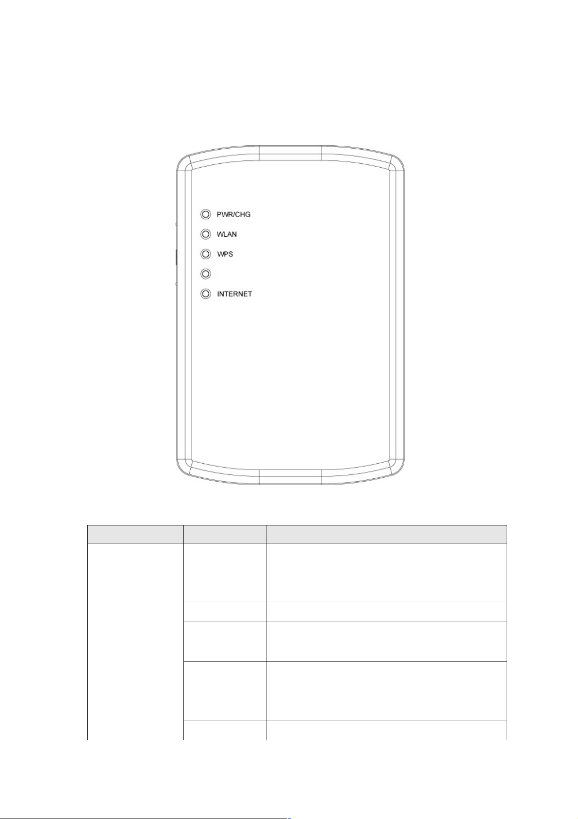
1- 5 Connect ions an d Ind ic ators
LEDS
LED Name
Light Status
Description
Green On
Router is switched on and correctly
powered or the battery is charged
completely.
Orange On
The battery is charging.
Orange
Flashing
Battery power is not enough, only 30
minutes remains.
Orange
Flashing
Fast
Battery power is not enough, only 10
minutes remains.
PWR/CHG
Off
Router is powered off.
ETHE RNET
5
Off
Wireless network is switched off.
WLAN
Flashing
Wireless LAN activity (transferring or
receiving data).
On
Wireless WPS function is enabled.
WPS
Off
Wireless WPS function is not enabled or
the connection is successfully.
On
ETHERNET port is connected.
Off
ETHERNET port is not connected.
ETHERNET
Flashing
ETHERNET activity (transferring or
receiving data).
On
Router is connected to the Internet.
Off
Router is not connected to the Internet.
INTERNET
Flashing
Router is connecting to the Internet.
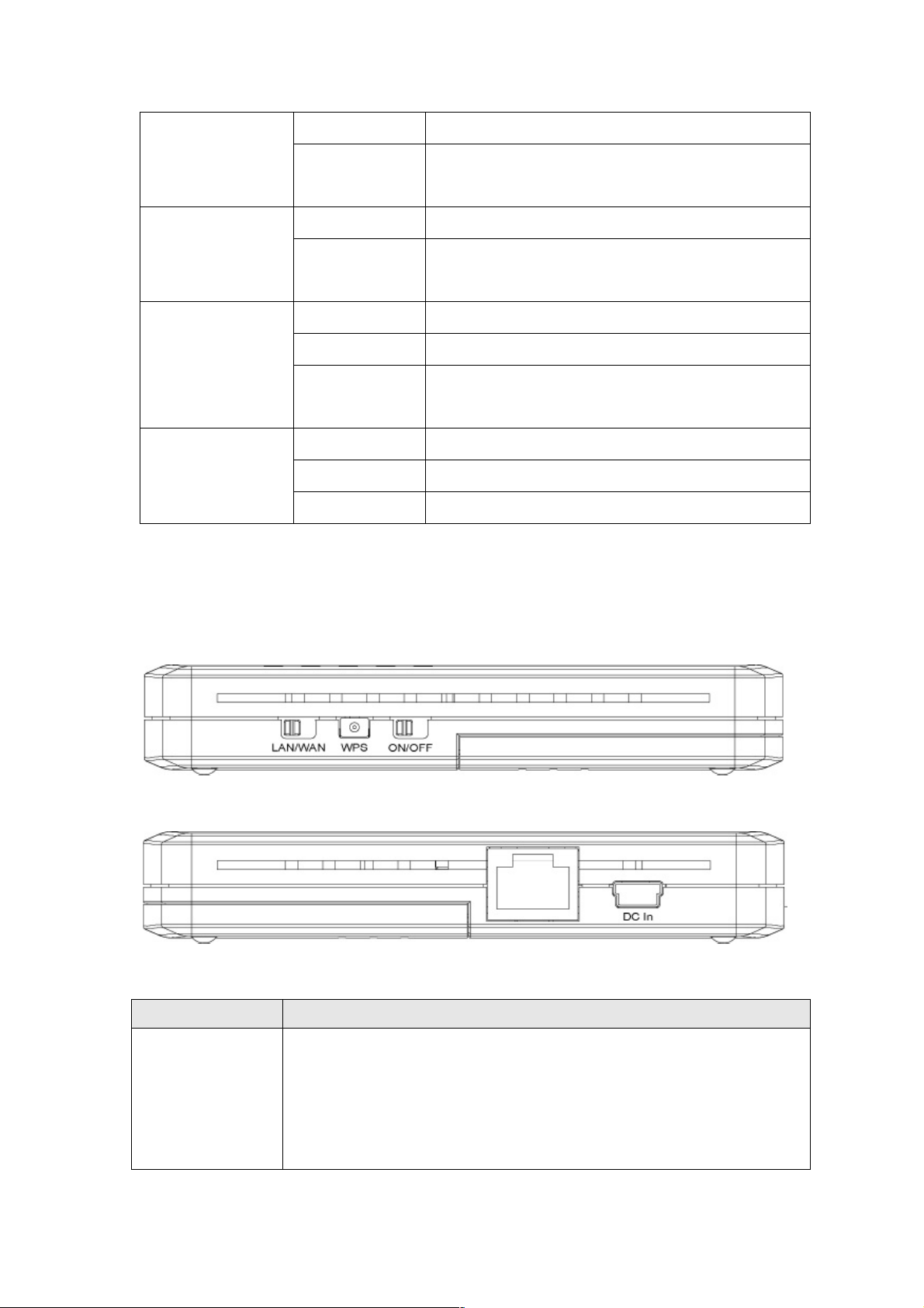
Right and Left Side Panels
Item Name
Description
LAN/WAN
Switch
Switch the Ethernet port to LAN or WAN. Switch to WAN
function if you want to access to the Internet through your
xDSL or Cable modem network service. WAN access can
also be a back up for 3G network. Please refer to Section
3-4 for more details.
RJ45
6
WPS
Start WPS function or reset the router to factory default
settings (clear all settings). Press this button and hold for
over 10 seconds to restore all settings to factory defaults,
or press this button for less than 5 seconds to start WPS
function.
ON/OFF
Switch the button to activate or deactivate the router.
DC in
Connect the supplied power adapter to this mini USB port
to charge the battery.
RJ45 Port
Local/ Wide Area Network (LAN/WAN) port.
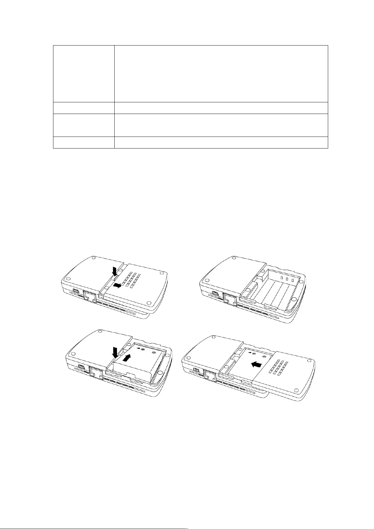
1-6 C hargi ng th e Bat tery
Before using the router, the battery needs to be charged. Charging
the battery takes about four hours.
1. Remove the battery compartment cover on the back of the
router, insert the included battery (if it’s not already in place),
then replace the cover, sliding it until the lath snaps securely
back in place.
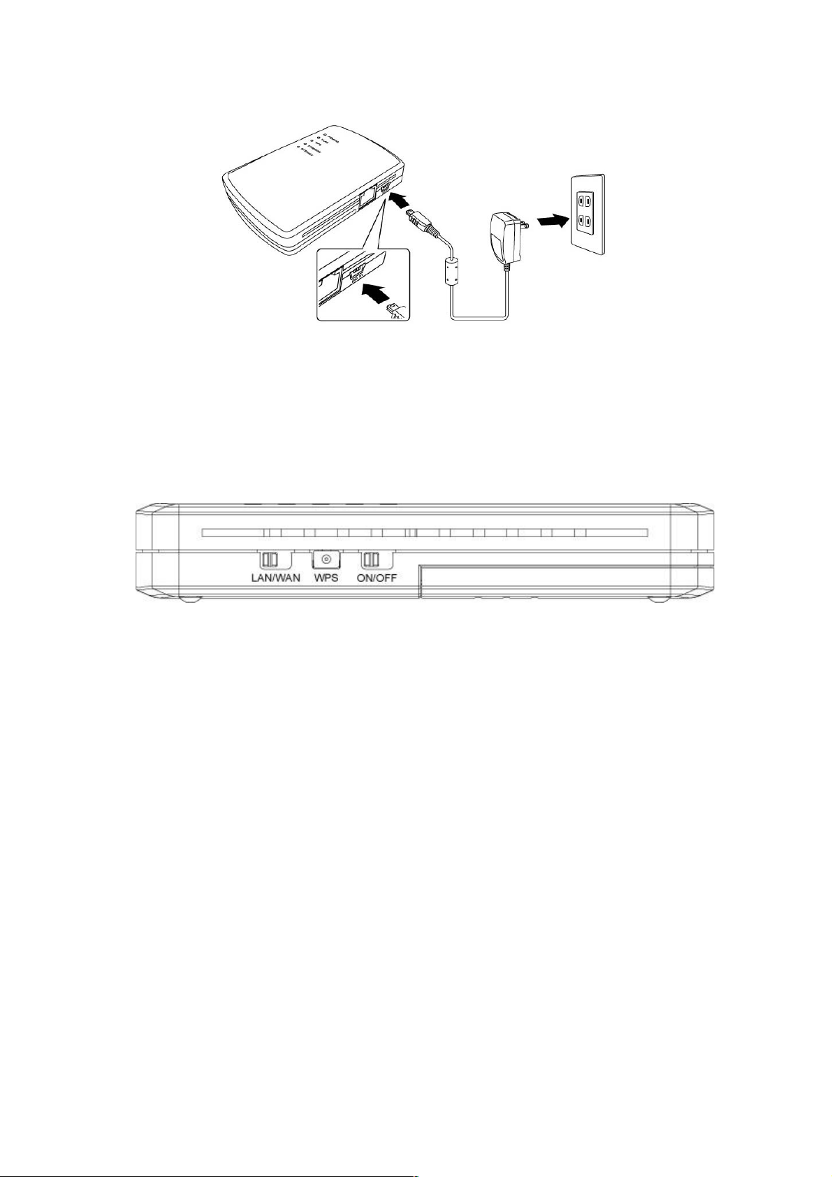
2. Plug the included power adapter into an AC outlet or an
automobile’s auxiliary power outlet, then connect it to the mini
USB port on the router (DC In). While the router battery is
charging, the PWR/CHG LED lights orange, then turns green
when the router battery is fully charged.
7
3. On the left side panel, set the On/Off switch to On. CAUTION:
Always switch the router off before removing the battery, and only
use the battery and power adapter or car charger included with
the router, as other types could be dangerous and damage the
router.
8
Chapter II: System and Network Setup
2-1 N etwor k Con nections
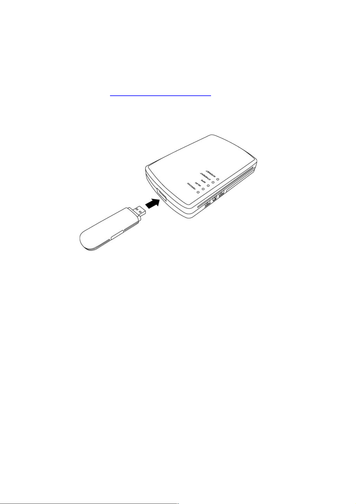
If needed, visit www.intellinet-network.com for a complete list of
compatible 3G USB modems.
1. Connect your 3G / 3.5G USB modem to the USB port on the top
panel of the router.
2. Connect your computer to the Ethernet port on the right side
panel of the router. NOTE: It’s recommended that you use a
cable connection through the Ethernet port for the router’s initial
configuration. The PWR/CHG LED should be lighted green and
the Ethernet LED should be on if the computer or other network
device connected to the router’s Ethernet port is turned on and
connected properly.
2-2 Con necti ng to the Route r via Web Bro wser
After the network connection is established, the next step is to set
up the router with proper network parameters so it can work
properly in your network environment.
Before you can connect to the router and start the configuration
procedures, your computer must be able to obtain an IP address
automatically (use dynamic IP address). If it’s set to use a static IP

9
address, or if you’re unsure, follow the instructions below to
configure your computer to use a dynamic IP address:
If the operating system of your computer is
Windows 95/98/Me - go to section 2-2-1
Windows 2000 - go to section 2-2-2
Windows XP - go to section 2-2-3
Windows Vista - go to section 2-2-4
2- 2-1 W in dows 95 /98/M e IP Addr es s Set up
1. Click Start (at the lower-left corner of your desktop), then click
Control Panel. Double-click the Network icon and the Network
window will appear. Select “TCP/IP,” then click “Properties.”
10
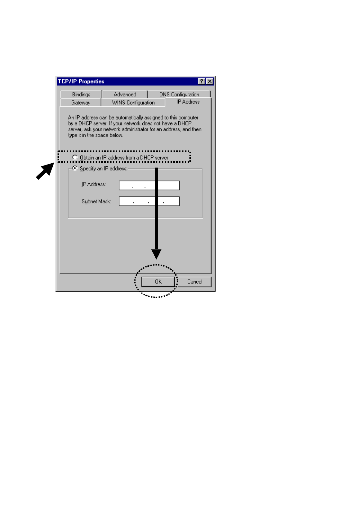
2. Select “Obtain an IP address from a DHCP server” and then click
“OK.”
11
2- 2-2 Win dows 20 00 IP A dd ress Se tup
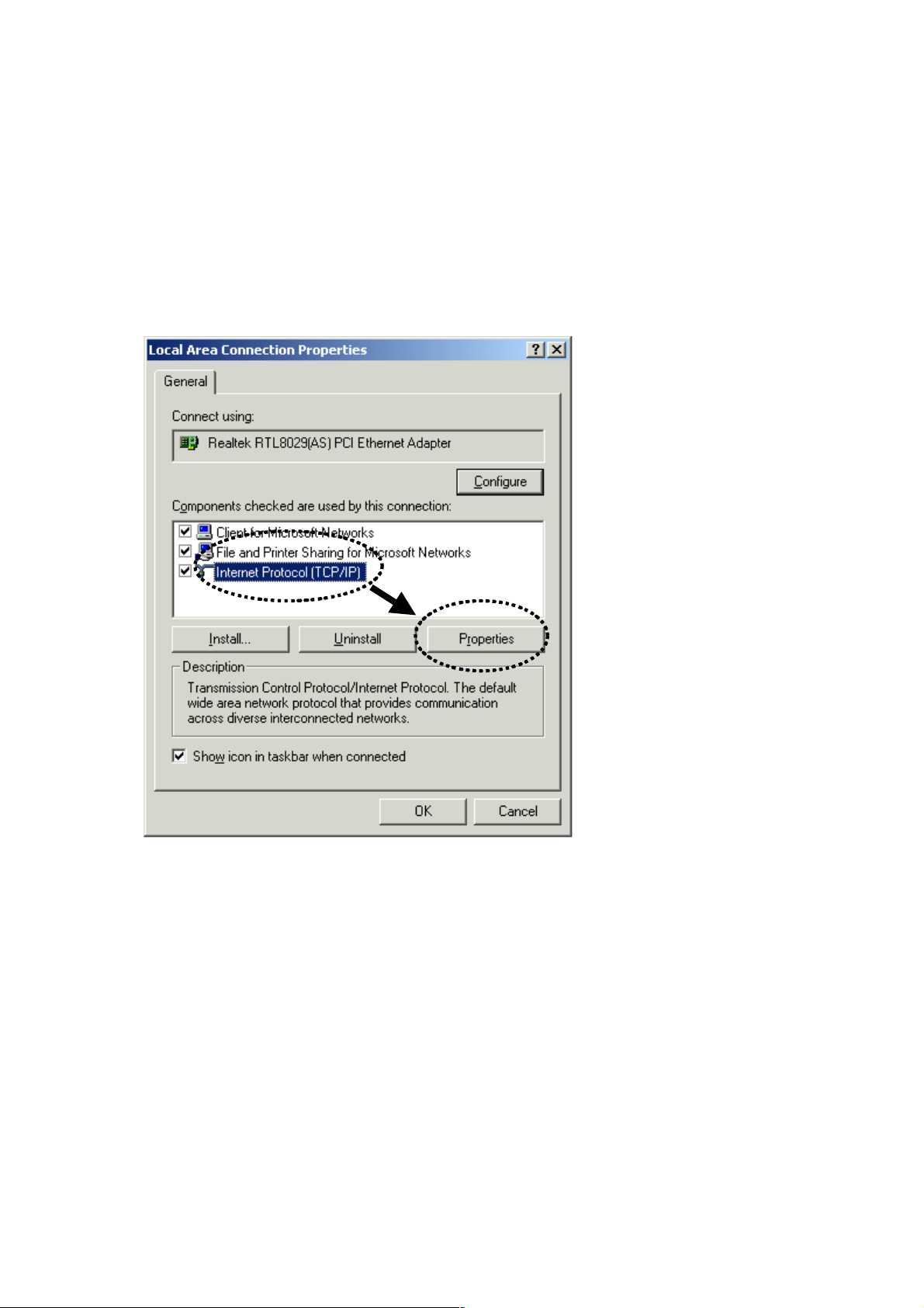
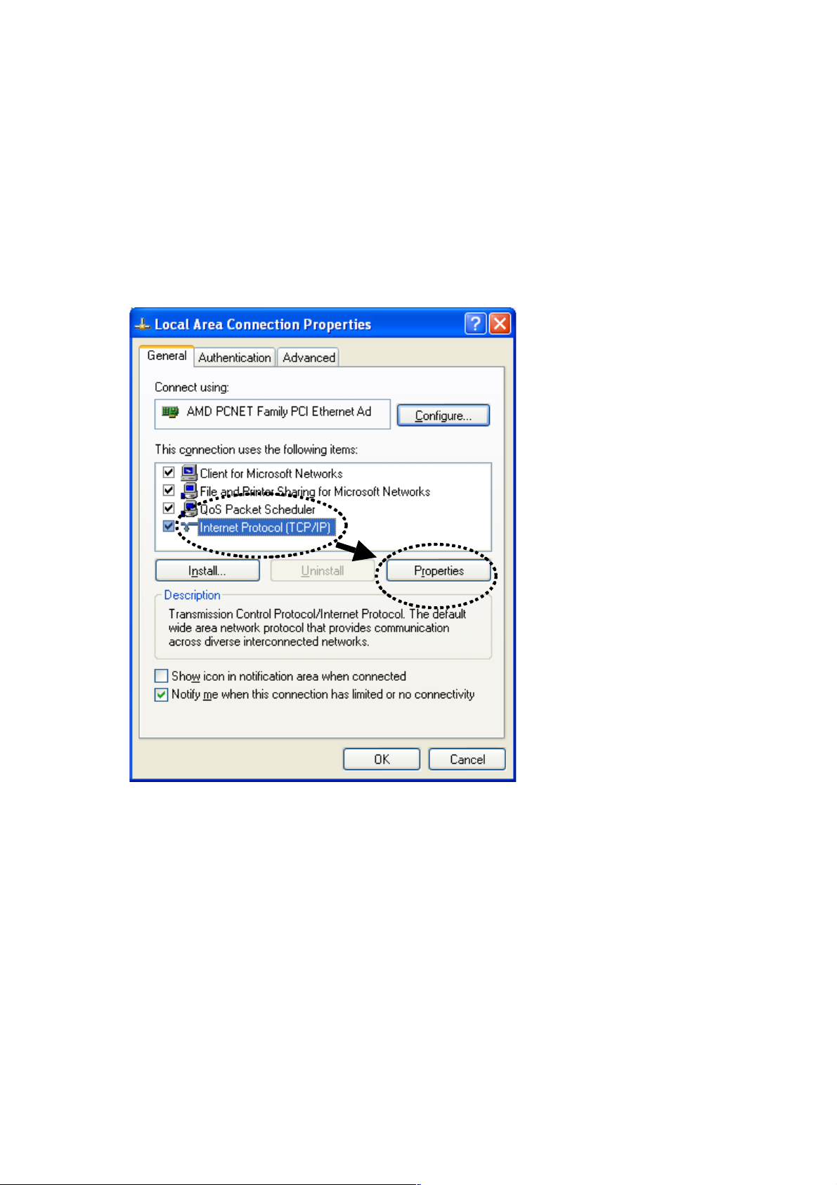
1. Click Start (at the lower-left corner of your desktop), then click
Control Panel. Double-click the Network and Dial-up
Connections icon; click Local Area Connection; the Local
Area Connection Properties window will appear. Select
“Internet Protocol (TCP/IP)” and then click “Properties.”
12
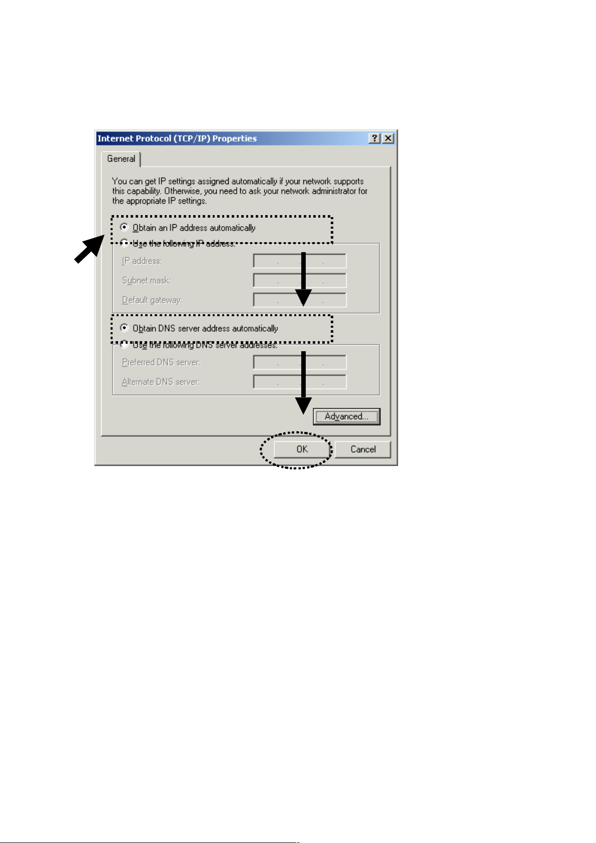
2. Select “Obtain an IP address automatically” and “Obtain DNS
server address automatically,” then click “OK.”
13
2- 2-3 Win dows XP IP Add ress Se tu p
1. Click Start (at the lower-left corner of your desktop), then click
Control Panel. Double-click the Network and Internet
Connections icon, click Network Connections, then
double-click Local Area Connection; the Local Area
Connection Status window will appear. Click “Properties.”

14
2. Select “Obtain an IP address automatically” and “Obtain DNS
server address automatically,” then click “OK.”
15
2- 2-4 Win dows Vi sta IP Address S etup
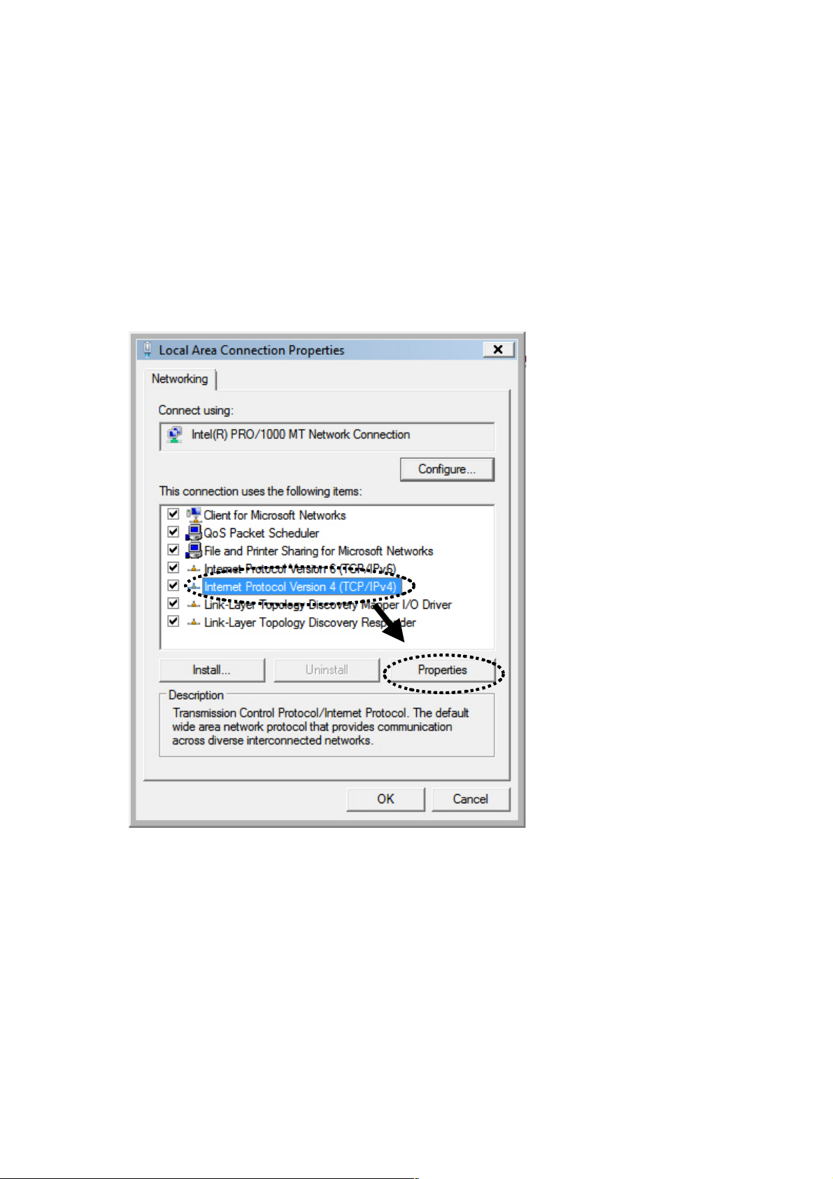
1. Click Start (at the lower-left corner of your desktop), then click
Control Panel. Click View Network Status and Tasks, and then
click Manage Network Connections. Right-click Local Area
Network, then select “Properties.” The Local Area
Connection Properties window will appear. Select “Internet
Protocol Version 4 (TCP / IPv4),” and then click “Properties.”

16
2. Select “Obtain an IP address automatically” and “Obtain DNS
server address automatically,” then click “OK.”
17
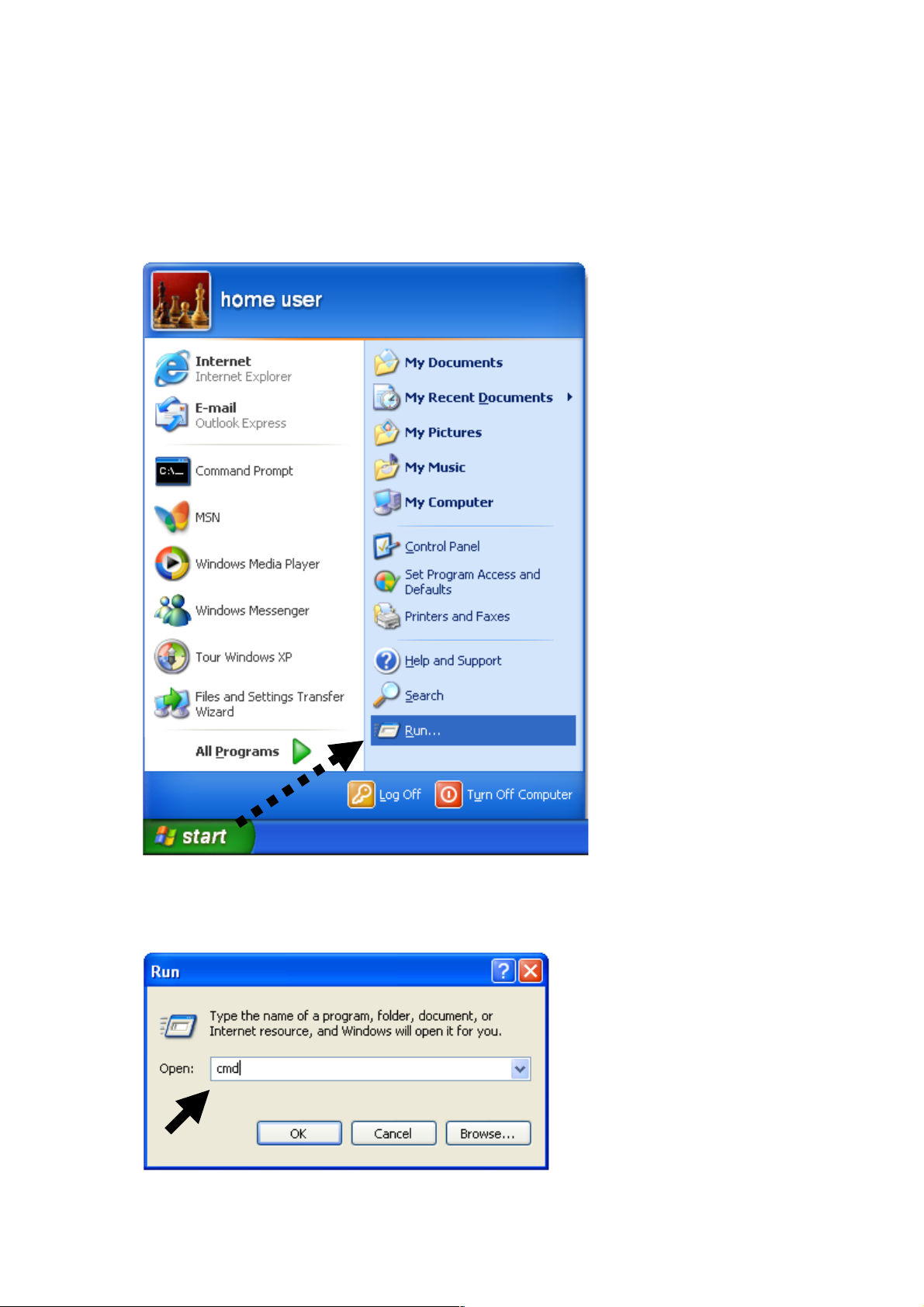
2- 2-5 R ou ter I P Address Lookup
After the IP address setup is complete, go to Start, then Run at the
bottom-lower corner of your desktop:
Input “cmd,” then click “OK.”
18
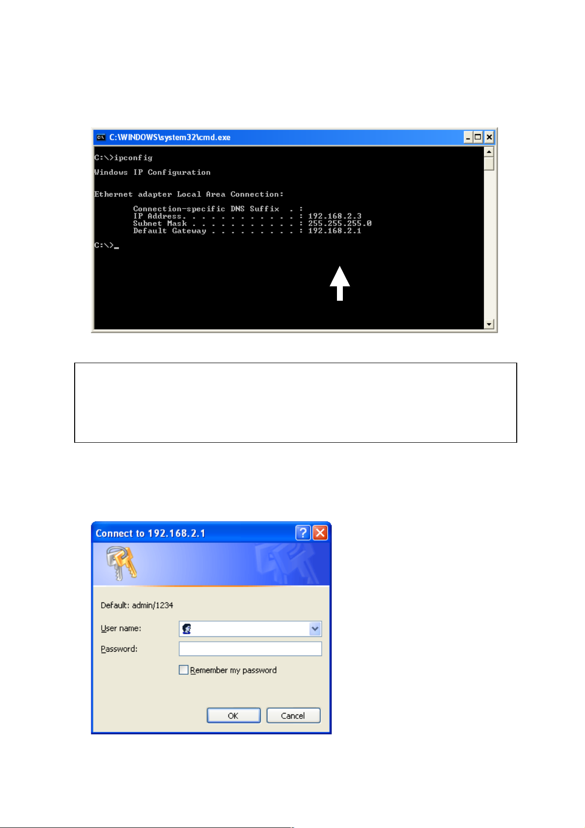
Input “ipconfig,” then press <Enter>. Check the IP address followed
by the default gateway (in this example, the IP address of the router
is 192.168.2.1).
After your computer obtains an IP address from the router, start
your Web browser and input the IP address of the router in the
address bar. The following window should display.
NOTE: If the IP address of the default gateway is not displayed, or if the
address following “IP Address” begins with “169,” re-check the network
connection between your computer and router, and/or go to the beginning
of this chapter to re-check each step of the network setup procedure.
19
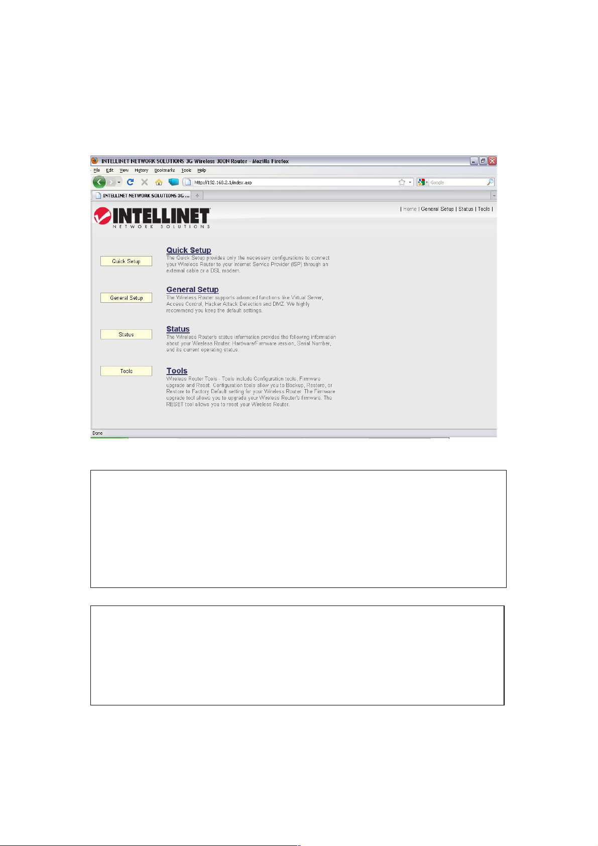
Enter a user name and password in their respective fields (default
user name is “admin”; default password is “1234”). Click “OK” band
you can see the Web management interface of the router.
NOTE: If you can’t see the Web management interface and you’re
being prompted to input the user name and password again, it means
you didn’t input the user name and password correctly: Re-enter the
user name and password. If you’re certain the user name and
password you entered are correct, refer to 4-2 Troubleshooting to
perform a factory reset to set the password back to its default value.
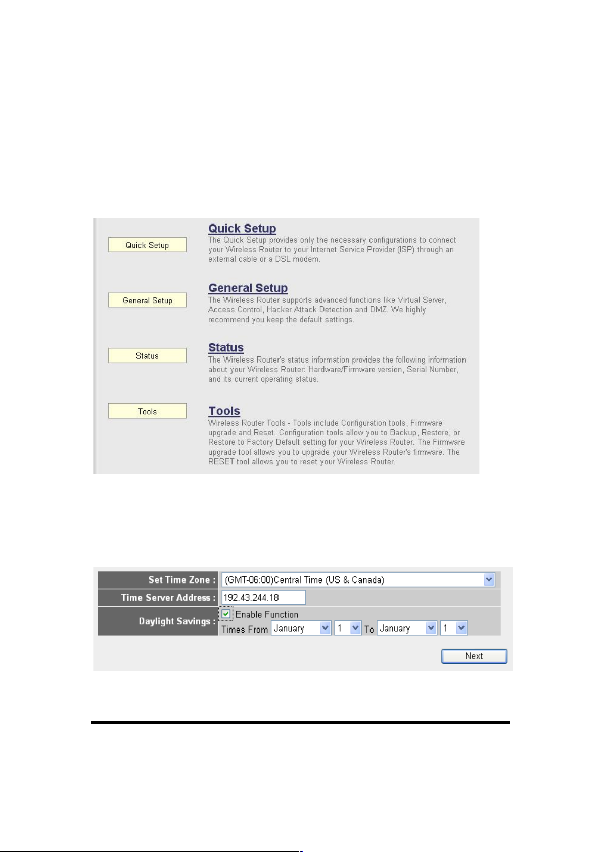
TIP: This page shows the four major menus: Quick Setup, General
Setup, Status and Tools. The shortcuts to these menus are at the
upper-right corner of every page so you don’t have to go back to the
first page.
20
2-3 U sing Quick Setu p
Quick Setup lets you complete all the required settings you need in
order to access the Internet very quickly.
Click “Quick Setup” on the left-hand navigation panel.
The following message will be displayed:
1. Set Time Zone
Below are descriptions of each option:
Set Time From the drop-down menu, select the
Zone (1): time zone for your location.
1
2
3
4

21
Time Server Input the IP address / host name of time server
Address (2): here.
Daylight If the country you live in uses Daylight Saving,
Savings (3): check “Enable Function” and choose the
duration of Daylight Saving.
After you finish the settings, click “Next” (4).
NOTE: There are several time servers available on the Internet:
129.6.15.28 (time-a.nist.gov)
132.163.4.101 (time-a.timefreq.bldrdoc.gov)
131.107.1.10 (time-nw.nist.gov)
If you find the time on the router is incorrect, try another time server.
22
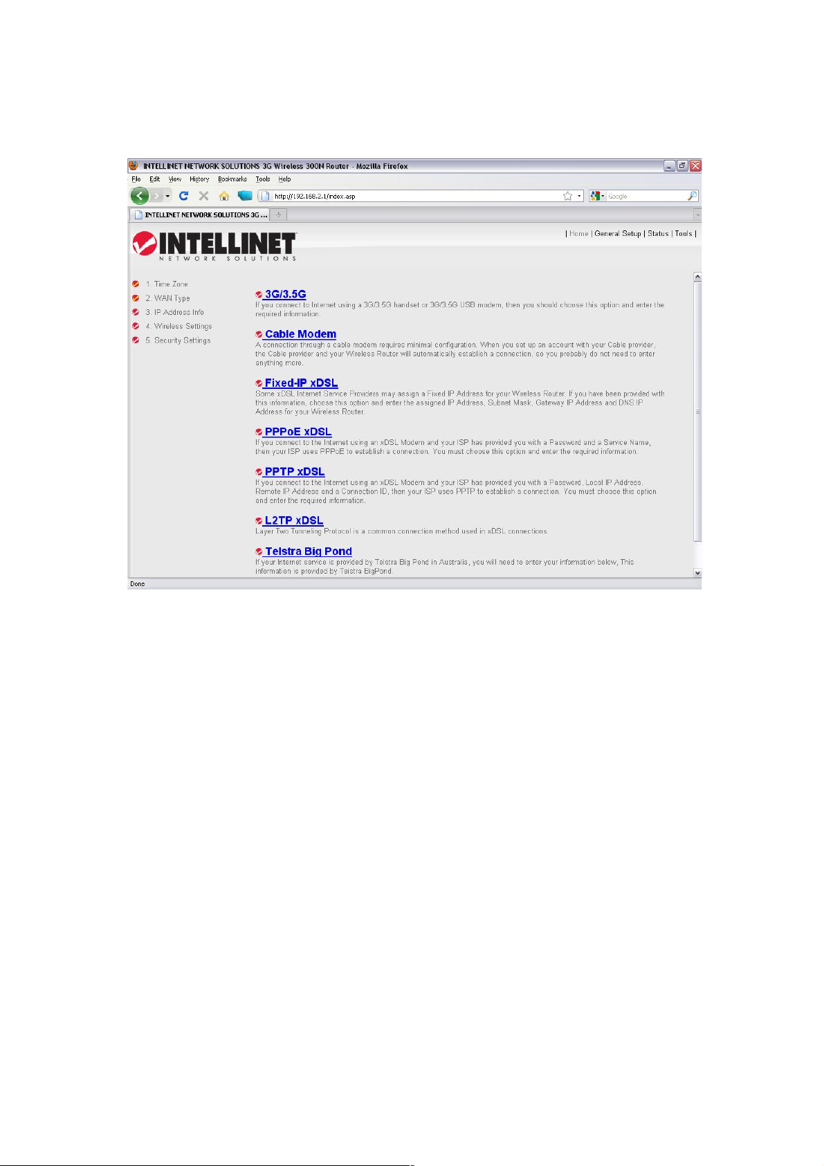
2. Broadband Type
Choose the broadband (Internet connection) type you’re using.
There are seven types of Internet connections:
3G/3.5G - go to section 2-3-1
Cable Modem - go to section 2-3-2
Fixed-IP xDSL - go to section 2-3-3
PPPoE xDSL - go to section 2-3-4
PPTP xDSL - go to section 2-3-5
L2TP xDSL - go to section 2-3-6
Telstra Big Pond - go to section 2-3-7
If you’re not sure which to use, contact your Internet service
provider. A wrong Internet connection type will cause connection
problems, and you will not be able to connect to the Internet.
To go back to a previous step, click “Back” at the bottom of the
page.
23
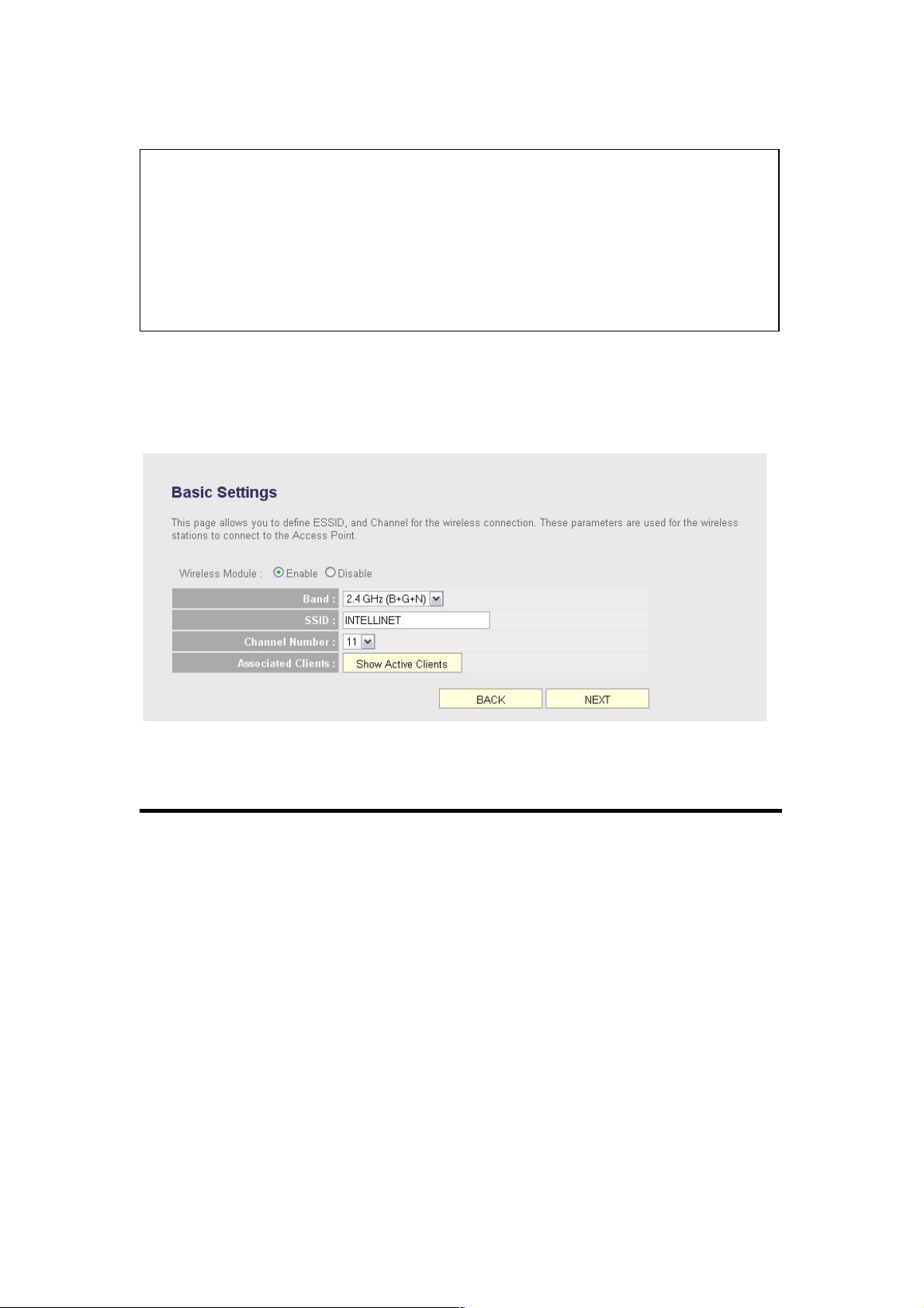
3. Basic Settings
Below are descriptions of each option:
Wireless Module (1): Click “Enable” to start using the wireless
function of this router, or select “Disable” to
close the wireless interface of this router.
Band (2): Select a band type from the drop-down list. It
allows you to set the router at 802.11b or
802.11g or 802.11n mode. You also can select
B+G or B+G+N mode to allow the router to
select an 802.11b, 802.11g or 802.11n
connection automatically.
SSID (3): This is the name of the wireless router. You can
enter any alphanumerical characters here
NOTE: Some service providers use DHCP (Dynamic Host
Configuration Protocol) to assign an IP address to you. In this case,
you can choose Cable Modem as the Internet connection type even
you’re using another connection type, like xDSL. Also, some cable
modems use PPPoE, so you can choose PPPoE xDSL for such a
connection even if you’re using a cable modem.
1
2 3 4 5 6

24
(maximum 32 characters). SSID is used to
identify your own wireless router from others
when there are other wireless routers in the
area. Default SSID is “INTELLINET”; it’s
recommended to change the default SSID
name to one that is easily recognizable, such
as “my home,” “office_room1,” etc.
Channel Number (4): Select a channel from the drop-down list.
Available channel numbers are 1 to 13 for
European countries; 1 to 11 for the U.S. You
can choose any channel number you want to
use, and almost all wireless clients can locate
the channel you’re using automatically without
any problem. However, it’s still useful to
remember the channel number you use. Some
wireless clients support manual channel
number select, and this would help in certain
scenarios where there is a radio communication
problem.
Associated Clients (5): Click “Show Active Clients” and an “Active
Wireless Client Table” will pop up. You can see
the status of all active wireless stations that are
connecting to the access point.
After you finish the settings, click “Next” (6); to go back to a
previous menu, click “Back.”
25
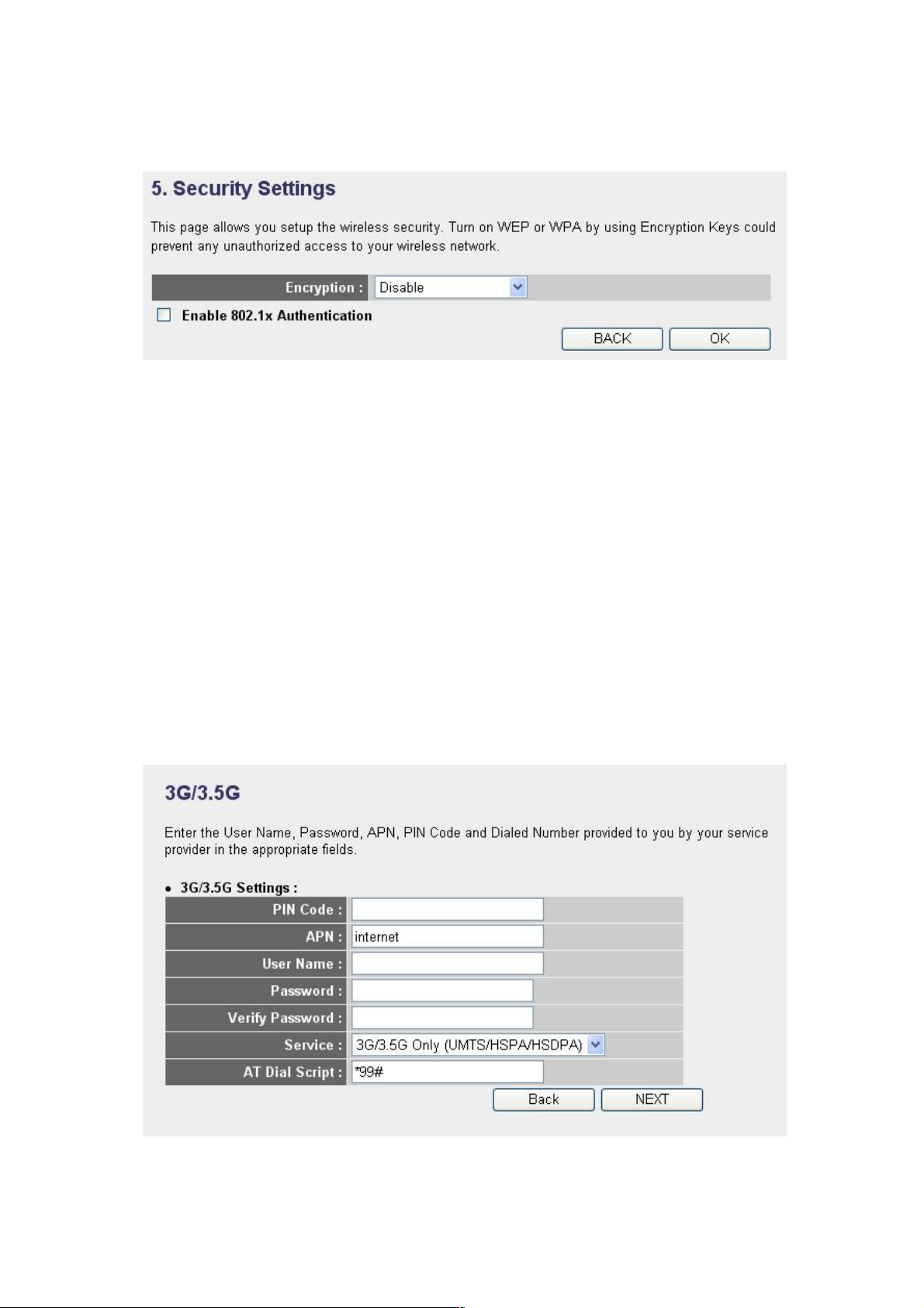
4. Security Settings
Choose the Encryption type you’re using from the drop-down list.
There are three types of Encryption:
WEP - go to section 2-7-3-2
WPA pre-shared key - go to section 2-7-3-3
WPA RADIUS - go to section 2-7-3-4
To go back to a previous step, click “Back” at the bottom of the
page.
2- 3-1 S et up Proc edure f or 3G /3 .5G
1
2 3 4
5
6 7 8

26
Below are descriptions of each option:
PIN Code (1): Enter a Pin Code for your UMTS or HSDPA or
EVDO connection. This is optional, and is only
required if your service provider asks you to do
so.
APN (2): Enter the APN code assigned by your Internet
service provider here.
User Name (3): Enter the user name assigned by your Internet
service provider here.
Password (4): Enter the password assigned by your Internet
service provider here.
Verify Password (5): Enter the password again for confirmation.
Service (6): Select your card type from the drop-down
menu.
AT Dial Script (7): Enter the dialed number for your UMTS or
HSDPA connection. The default is *99#. This
field should not be altered except when
required by your service provider.
After you finish the settings, click “Next” (8); to go back to a
previous menu, click “Back.”

27
2- 3-2 S et up Proc edure f or Cabl e Modem
Below are descriptions of each option:
Host Name (1): Enter the host name of your computer This is
optional, and is only required if your service
provider asks you to do so.
MAC Address (2): Enter the MAC address of your computer here if
your service provider only permits computers
with a certain MAC address to access the
Internet. If you’re using a computer that used to
connect to the Internet via cable modem, you
can simply click “Clone Mac address” to fill the
MAC address field with the MAC address of
your computer.
After you finish the settings, click “Next” (3); to go back to a
previous menu, click “Back.”
1 2 3

28
2- 3-3 S et up Proc edure f or Fi xe d-IP xD SL
Below are descriptions of the options:
IP address (1): Enter the IP address assigned by your service
provider.
Subnet Mask (2): Enter the subnet mask assigned by your
service provider.
DNS Address (3): Enter the IP address of the DNS server
provided by your service provider.
Default Gateway Enter the IP address of the default gateway
(4): provided by your service provider.
When you finish the settings, click “Next” (5); to go back to a
previous menu, click “Back.”
1
2 3 4
5
NOTE: You can choose this Internet connection method if your
service provider assigns a fixed IP address (also know as a static
address) to you, and you’re not using DHCP or PPPoE protocols.
You must use the addresses provided by your Internet service
provider. Wrong settings will cause connection problems.

29
2- 3-4 S et up Proc edure f or PPPo E xDSL
Below are descriptions of each option:
User Name (1): Enter the user name assigned by your Internet
service provider here.
Password (2): Enter the password assigned by your Internet
service provider here.
Service Name (3): Assign a name to this Internet service
(optional).
MTU (4): Enter the MTU value of your network
connection here. If you don’t know, contact
your ISP.
Connection Select the connection type of the Internet
Type (5): connection you want to use (detailed
explanation listed below).
Idle Time Out (6): Enter the idle time out (detailed explanation
listed below).
1 2 4 3 5 6 7

30
When you finish the settings, click “Next” (7); to go back to a
previous menu, click “Back.”
2- 3-5 S et up Proc edure f or PPTP xDSL
PPTP xDSL requires two kinds of settings: WAN Interface Settings
(setup IP address) and PPTP Settings (PPTP user name and
password). First, WAN Interface Settings:
Select how you obtain an IP address from your service provider.
You can choose “Obtain an IP address automatically” (equal to
DHCP — refer to “Cable Modem” above), or “Use the following IP
address” (i.e., a static IP address).
MTU - If you don’t know what it is, ask your service provider for a
proper value.
Connection Type - There are 3 options: “Continuous” keeps the
Internet connection alive (doesn’t disconnect); “Connect on
Demand” only connects to the Internet when there’s a connection
attempt; “Manual” only connects to the Internet when “Connect” is
clicked, and disconnects when “Disconnect” is clicked.
Idle Time Out: Specify the time to shut down the Internet connection
after no Internet activity is detected. This option is only available
when the connection type is Connect on Demand.

31
WAN interface settings must be correctly set; otherwise, the
Internet connection will fail even if the PPTP settings are correct.
Contact your Internet service provider if you don’t know how you
should fill in these fields.
Next, PPTP Settings:
Below are descriptions of each option:
User Name (1): Enter the user name assigned by your Internet
service provider here.
Password (2): Enter the password assigned by your Internet
service provider here.
PPTP Enter the IP address of the PPTP gateway
Gateway (3): assigned by your Internet service provider here.
Connection Enter the connection ID here. This is
ID (4): optional and you can leave it blank.
MTU (5): Enter the MTU value of your network
connection here. If you don’t know it, contact
your ISP.
BEZEQ-ISRAEL (6): Select only if you’re using the service provided
1
2
3 4 5
6
7
9
8

32
by the BEZEQ network in Israel.
Connection Type (7): Select the connection type of Internet
connection you want to use (refer to the last
section for detailed descriptions).
Idle Time Out (8): Enter the idle time out of the Internet
connection you want to use (refer to the last
section for detailed descriptions).
When you finish the settings, click “Next” (9); to go back to a
previous menu, click “Back.”
2- 3-6 S et up Proc edure f or L2 TP xDSL
L2TP is another popular connection method for xDSL and other
Internet connection types, and all required setting items are the
same with PPTP connection.
Like PPTP, there are two kinds of required settings. First, WAN
Interface Settings:
Select how you obtain an IP address from your service provider.
You can choose “Obtain an IP address automatically” (equal to
DHCP — refer to “Cable Modem” above), or “Use the following IP
address” (i.e., a static IP address).
WAN interface settings must be correctly set; otherwise, the
Internet connection will fail even if the PPTP settings are correct.
Contact your Internet service provider if you don’t know how you
33
should fill in these fields.
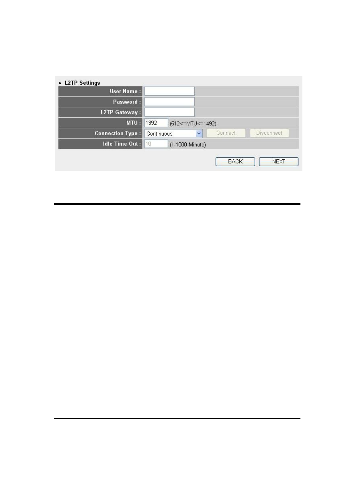
Next, L2TP Settings:
Below are descriptions of each option:
User Name (1): Enter the user name assigned by your Internet
service provider here.
Password (2): Enter the password assigned by your Internet
service provider here.
L2TP Gateway (3): Enter the IP address of PPTP gateway
assigned by your Internet service provider here.
MTU (4): Enter the MTU value of your network
connection here. If you don’t know it, contact
your ISP.
Connection Select the connection type of Internet
type (5): connection you want to use (refer to the last
section for detailed descriptions).
Idle Time Out (6): Enter the idle time out of the Internet
connection you want to use (refer to the last
section for detailed descriptions).
When you finish the settings, click “Next” (7); to go back to a
previous menu, click “Back.”
1
2
4 3 5
7
6

34
2- 3-7 S et up Proc edure f or Tels tra B ig Pond
This setting only works when you’re using Telstra Big Pond’s
network service in Australia.
User Name (1): Enter the user name assigned by Telstra.
Password (2): Enter the password assigned by Telstra.
Assign login Check this box to choose a login server by
server manually yourself.
(3):
Server Enter the IP address of the login server here.
IP Address (4):
When you finish the settings, click “Next” (5); to go back to a
previous menu, click “Back.”
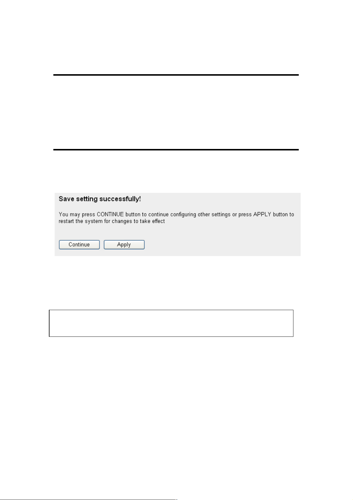
When all settings are completed, you’ll see the following message
displayed on your Web browser:
1
2
3 4 5

35
Click “Apply” to prepare to restart the router, and you’ll see this
message:
Wait for about 30 seconds, then click “OK!” You’ll be back to the
router management interface, and the router is ready with new
settings.

36
2-4 Bas ic Se tup
In this chapter, you’ll know how to change the time zone, password
and remote management settings. Start your Web browser and log
on to the router’s Web management interface, then click “General
Setup” on the left (or click the “General Setup” link at the
upper-right corner of the screen).
2- 4-1 T im e Zone and Tim e Auto- Sy nchro ni zatio n
In the General Setup menu, click “System” on the left side of the
Web management interface, then click “Time Zone.” The following
message will be displayed on your Web browser:
1 2 3
37
Below are descriptions of each option:
Time Zone (1): Select a time zone from the drop-down list.
Time Server Enter the IP address or host name of the time
Address (2): server here.
Daylight Check the “Enable” box and set the
Savings (3): duration of Daylight Saving.
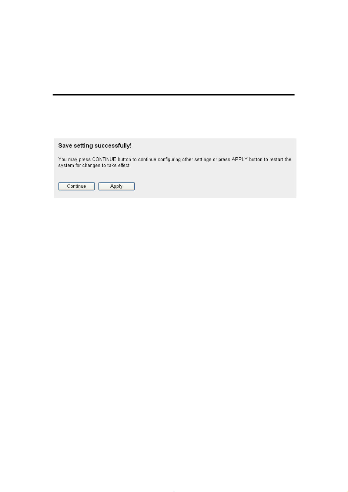
When you finish, click “Apply.” You’ll see the following message
displayed on the Web browser:
Click “Continue” to save the settings made and go back to the Web
management interface; click “Apply” to save the settings made and
restart the router so the settings will take effect after it reboots.
2- 4-2 C ha nging t he Mana gement Pa ssword
The default password of this router is 1234, and it’s displayed on
the login prompt when accessed from the Web browser. There’s a
security risk if you don’t change the default password, since
everyone can see it. This is very important when you have the
wireless function enabled.
NOTE: You can refer to the instructions given in last chapter, Using
Quick Setup, for detailed descriptions on time zone settings.
38
To change the password, click “System” on the left side of the Web
management interface, then click “Password Settings.” The
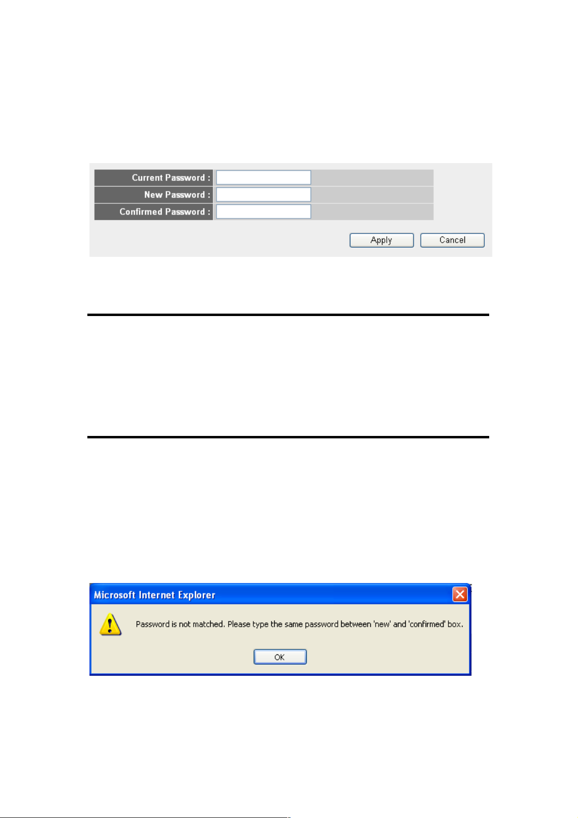
following message will be displayed on your Web browser:
Below are descriptions of each option:
Current Enter the current password here.
Password (1):
New Password (2): Enter the new password here.
Confirmed Enter the new password here again.
Password (3):
When you finish, click “Apply.” If you want to keep the original
password unchanged, click “Cancel.”
If the password you entered in the “New Password” (2) and
“Confirmed Password” (3) fields aren’t the same, you’ll see the
following message:
Re-enter the new password if you see above message.
2
3
39
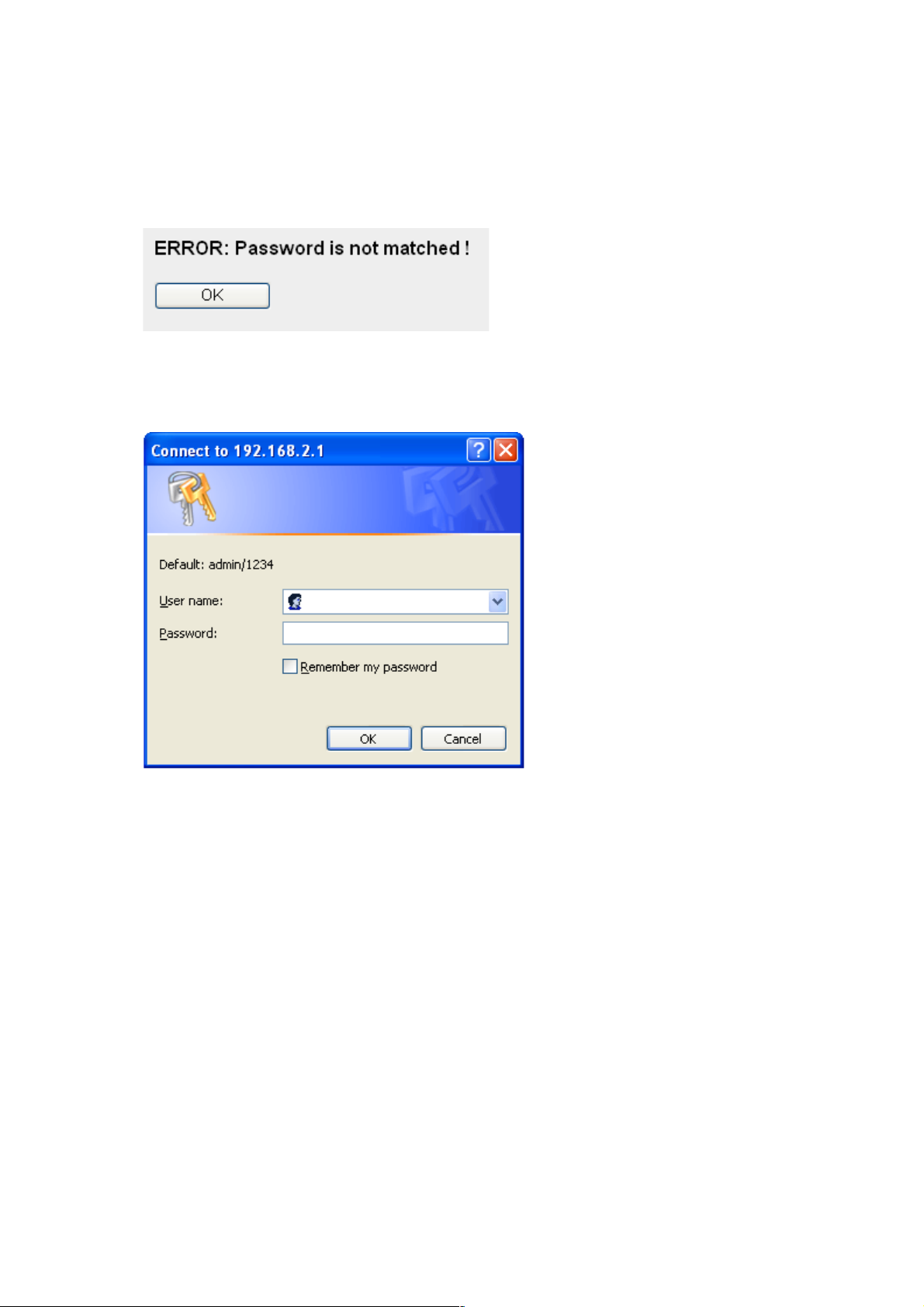
If you see the
following
message, the content in the “Current
Password” field is wrong. Click “OK” to go back to the previous
menu, and try to enter the current password again.
If the current and new passwords are correctly entered, after you
click “Apply” you’ll be prompted to enter your new password:
Use the new password to enter the Web management interface
again, and you should be able to log in with new password.
2- 4-3 R em ote Man agement
This router does not allow management access from the Internet to
prevent possible security risks (as when a too-simple password is
used or when the default password isn’t changed). However, you
can still management this router from a specific IP address by
enabling the Remote Management function.
Click “System” on the left side of the Web management interface,

40
then click “Remote Management.” The following message will be
displayed on your Web browser:
Below are descriptions of each option:
Host Address (1): Input the IP address of the remote host for
which you want to initiate management access.
Port (2): You can define the port number through which
the router should expect an incoming request. If
you’re providing a Web service (default port
number is 80), you should try to use another
port number. You can use the default port
setting (8080), or something like 32245 or 1429
(any integer between 1 and 65534).
Enabled (3): Select the field to start the configuration.
When you finish the settings, click “Apply” and you’ll see the
following message displayed on the Web browser:
Click “Continue” to save the settings and go back to the Web
management interface; click “Apply” to save the settings and restart
the router so the settings will take effect after it reboots.

41
NOTE: When you want to manage this router from another computer
on the Internet, you need to input the IP address and port number of
this router. If your Internet service provider assigns you a static IP
address, it will not be a problem; but if the IP address your service
provider assigns you will vary every time you establish an Internet
connection, this will be a problem.
Either ask your service provider to give you a static IP address, or
use dynamic IP to host name mapping services like DDNS. Refer to
section 2-5-8 DDNS Client for details.
NOTE: The default port number the Web browser will use is 80. If the
“Port” setting on this page is not 80, you need to assign the port
number in the address bar of the Web browser manually. For
example, if the IP address of this router is 1.2.3.4 and the port
number you set is 8888, you need to input the following address in
the address bar of the Web browser:
http://1.2.3.4:8888

42
2-5 Set ting Up th e Int ernet Conn ectio n (WA N)
Internet connection setup can be done by using Quick Setup as
described in Section 2-3. However, you can also set up WAN
connections up by using the WAN configuration menu. You can
also set advanced functions like DDNS (Dynamic DNS) here.
Click “WAN” on the left side of the Web management interface, and
the screen below will be displayed on your Web browser.
Select an Internet connection method based on the type of
connection you’re using. You can either click the connection
method on the left (1) or right (2). If you select the connection
method on the right, click “More Configuration” after a method is
selected.
3G/3.5G - go to section 2-5-1
Dynamic IP - go to section 2-5-2
Static IP - go to section 2-5-3
PPPoE - go to section 2-5-4

43
PPTP - go to section 2-5-5
L2TP - go to section 2-5-6
Telstra Big Pond - go to section 2-5-7
DNS - go to section 2-5-8
DDNS - go to section 2-5-9
2- 5-1 S et up Proc edure f or 3G /3 .5G
Below are descriptions of each option:
PIN Code (1): Enter the Pin Code for your UMTS or HSDPA
connection. This is optional, and is required
only if your service provider asks you to do so.
APN (2): Enter the access point name.
User Name (3): Enter the user name assigned by your Internet
service provider here.
Password (4): Enter the password assigned by your Internet
service provider here.
1
2
3
4
5
6 7 8

44
Verify Password (5): Enter the password again for confirmation.
Service (6): Select your card type from the drop-down
menu.
AT Dial Script (7): Enter the dialed number for your UMTS or
HSDPA connection. The default is *99#. This
field should not be altered except when
required by your service provider.
After you finish the settings, click “Apply” (8); to remove any value
you entered, click “Cancel.”
After you click “Apply,” the following message will be displayed on
your Web browser:
Click “Continue” to go back and continue with the router setup, or
click “Apply” to reboot the router so the settings will take effect.
(Wait for about 30 seconds while router is rebooting.)

45
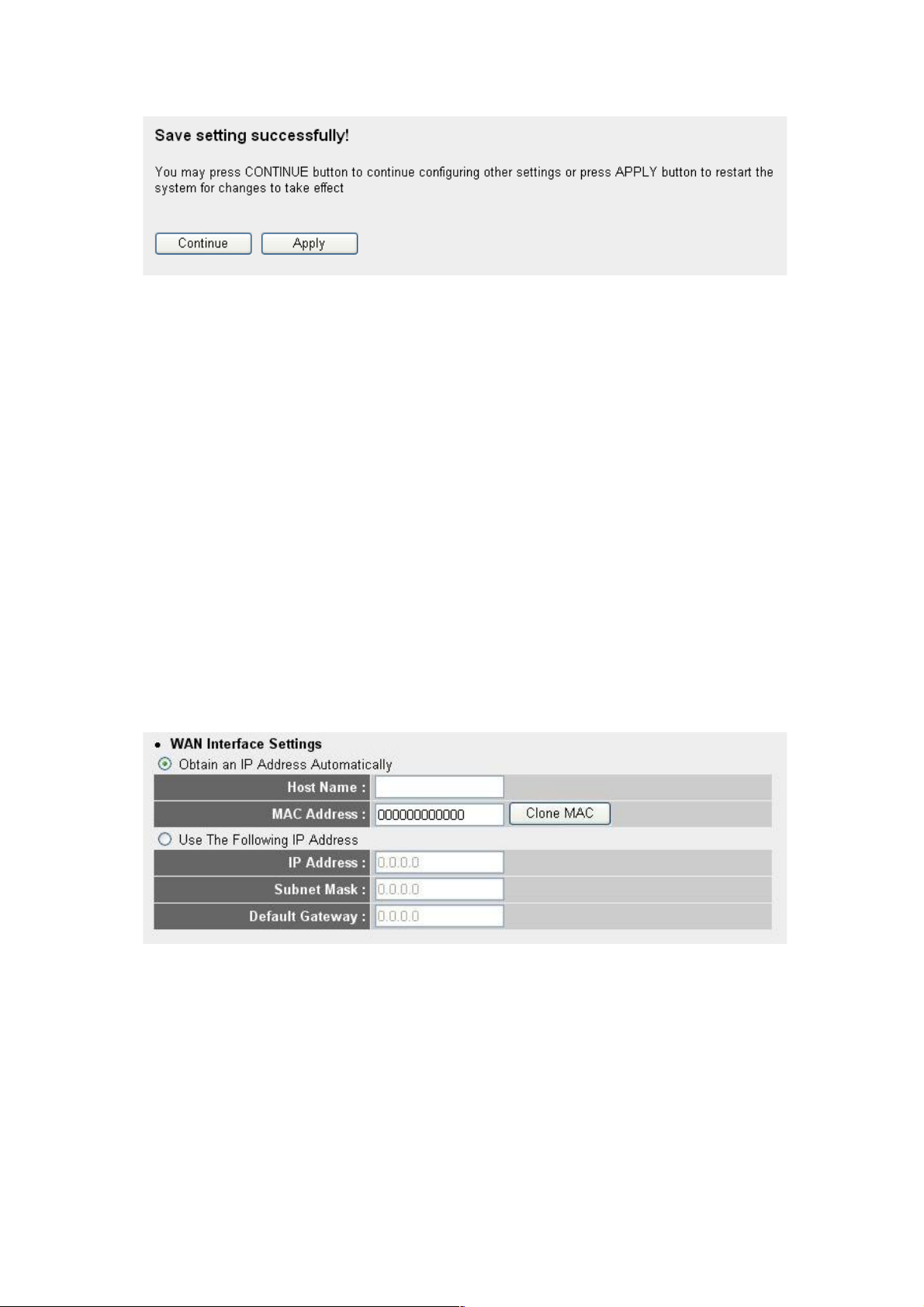
2- 5-2 S et up Proc edure f or Dyna mic IP
Below are descriptions of each option:
Host Name (1): Enter the host name of your computer. This is
optional, and is only required if your service
provider asks you to do so.
MAC Address (2): Enter the MAC address of your computer if your
service provider only permits computers with
certain MAC addresses Internet access. If
you’re using a computer that’s used to connect
to the Internet via cable modem, you can simply
press “Clone Mac address” to fill the MAC
Address field with the MAC address of your
computer.
After you finish the settings, click “Apply” (3); to remove any value
you entered, click “Cancel.”
After you click “Apply,” the following message will be displayed on
your Web browser:
1 2 3

46
Click “Continue” to go back and continue with the router setup, or
click “Apply” to reboot the router so the settings will take effect.
(Wait for about 30 seconds while the router is rebooting.)
2- 5-3 S et up Proc edure f or Stat ic IP
Below are descriptions of each option:
IP address (1): Enter the IP address assigned by your
service provider.
Subnet Mask (2): Enter the subnet mask assigned by your
service provider
Gateway Address (3): Enter the IP address of the DNS server
provided by your service provider.
After you finish the settings, click “Apply” (4) and the following
1
2
3
4

47
message will be displayed on your Web browser:
Click “Continue” to go back and continue with the router setup, or
click “Apply” to reboot the router so the settings will take effect.
(Wait for about 30 seconds while the router is rebooting.)
If you want to reset all settings on this page back to previously
saved values, click “Cancel.”
2-5-4 Setup Procedure for PPPoE
Below are descriptions of each option:
User Name (1): Enter the user name assigned by your Internet
service provider here.
1
2
4
3
7

48
Password (2): Enter the password assigned by your Internet
service provider here.
Service Name (3): Enter a name for this Internet service. (This is
optional.)
MTU (4): Enter the MTU value of your network
connection here. If you don’t know it, contact
your ISP.
Connection Select the connection type of the Internet
Type (5): connection you want to use.
Continuous – The connection will be kept on. If the
connection is interrupted, the router will re-connect
automatically.
Connect On-Demand – Only connects when you
want to surf the Internet. “Idle Time Out” is set to
stop the connection when the network traffic is not
sending or receiving after an idle time.
Manual – After you have selected this option, you
will see the “Connect” button and “Disconnect”
button. Click “’Connect” and the router will connect
to the ISP. If you want to stop the connection, click
“Disconnect.”
Idle Time Out (6): If you have selected “Connect-On-Demand,
input the idle time out.
After you finish the settings, click “Apply” (7) and the following
message will be displayed on your Web browser:
49
Click “Continue” to go back and continue with the router setup
procedure, or click “Apply” to reboot the router so the settings will
take effect. (Wait for about 30 seconds while the router is
rebooting.)
If you want to reset all settings on this page back to previously
saved values, click “Cancel.”
2- 5-5 S et up Proc edure f or PPTP
PPTP requires two kinds of settings: WAN Interface Settings (set
up an IP address) and PPTP Settings (PPTP user name and
password). First, the WAN Interface Settings:
Select how you obtain an IP address from your service provider
here. You can choose “Obtain an IP address Automatically” (equal
to DHCP; refer to the Cable Modem section above), or “Use the
Following IP Address” (i.e., static IP address).
WAN interface settings must be correctly set, or the Internet
connection will fail even if the PPTP settings are correct. Contact

50
your Internet service provider if you don’t know how you should fill
in these fields.
Next, PPTP Settings:
Below are descriptions of each option:
User Name (1): Enter the user name assigned by your Internet
service provider here.
Password (2): Enter the password assigned by your Internet
service provider here.
PPTP Gateway (3 Enter the IP address of PPTP gateway
assigned by your Internet service provider here.
Connection ID (4): Enter the connection ID here. (This is optional:
You can leave it blank.)
MTU (5): Enter the MTU value of your network
connection here. If you don’t know it, contact
your ISP.
BEZEQ-ISRAEL (6): If you are connecting to the BEZEQ network in
Israel, enable this function.
Connection Select the connection type of the Internet
1
3
4 5 7
8 9 6

51
Type (7): connection you want to use. (Refer to section
2-5-3 for detailed descriptions.)
Idle Time Out (8): Enter the idle time out of the Internet
connection you want to use. (Refer to section
2-5-3 for detailed descriptions.)
When you finish the settings, click “Apply” (9) and the following
message will be displayed on your Web browser:
Click “Continue” to go back and continue with the router setup
procedure, or click “Apply” to reboot the router so the settings will
take effect. (Wait for about 30 seconds while the router is
rebooting.)
If you want to reset all settings on this page back to previously
saved values, click “Cancel.”
2- 5-6 S et up Proc edure f or L2 TP
1
2
4 3 5
7
6

52
Below are descriptions of each option:
User Name (1): Enter the user name assigned by your Internet
service provider here.
Password (2): Enter the password assigned by your Internet
service provider here.
L2TP Gateway (3): Enter the IP address of the PPTP gateway
assigned by your Internet service provider here.
MTU (4): Enter the MTU value of your network
connection here. If you don’t know it, you can
use the default value.
Connection Select the connection type of the Internet
type (5): connection you want to use. (Refer to the last
section for detailed descriptions.)
Idle Time Out (6): Enter the idle time out of the Internet
connection you want to use. (Refer to the last
section for detailed descriptions.)
When you finish the settings, click “Apply” (7) and the following
message will be displayed on your Web browser:
Click “Continue” to go back and continue with the router setup
procedure, or click “Apply” to reboot the router so the settings will
take effect. (Wait for about 30 seconds while the router is
rebooting.)
53
If you want to reset all settings on this page back to previously
saved values, click “Cancel.”
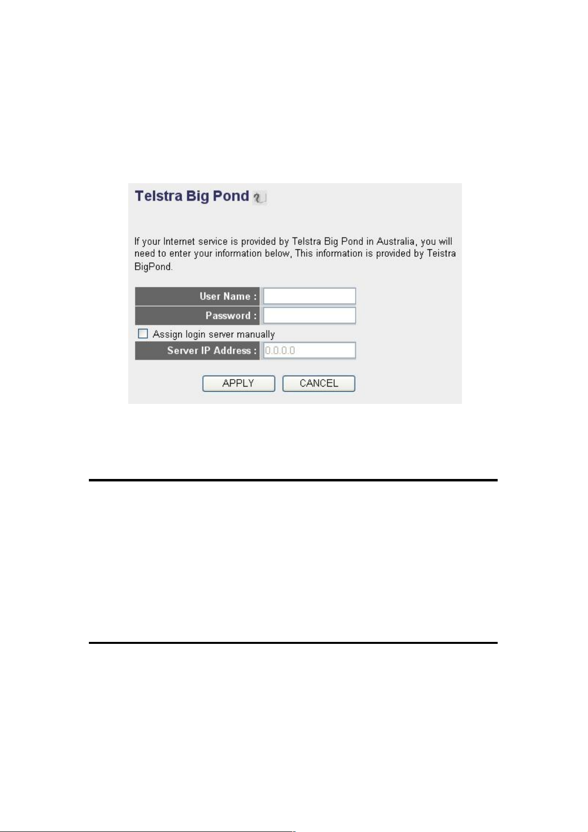
2- 5-7 S et up Proc edure f or Te ls tra B ig Pond
These settings only work when you’re using Telstra Big Pond’s
network service in Australia.
User Name (1): Enter the user name assigned by Telstra.
Password (2): Enter the password assigned by Telstra.
Assign login Check this box to choose a login server by
server manually yourself.
(3):
Server IP Address (4): Enter the IP address of login server here.
When you finish the settings, click “Apply” (5) and the following
message will be displayed on your Web browser:
1
2
3 4 5

54
Click “Continue” to go back and continue with the router setup
procedure, or click “Apply” to reboot the router so the settings will
take effect. (Wait for about 30 seconds while the router is
rebooting.)
If you want to reset all settings on this page back to previously
saved values, click “Cancel.”
2- 5-8 S et up Proc edure f or DNS
If you select “Dynamic IP” or “PPPoE” as the Internet connection
method, at least one DNS server’s IP address should be assigned
automatically. However, if you have a preferred DNS server, or your
service provider didn’t assign the IP address of a DNS server for
any reason, you can input the IP address of the DNS server here.
1
2
3

55
Below are descriptions of each option:
Primary DNS (1): Enter the IP address of the DNS server
provided by your service provider.
Secondary DNS (2): Enter the IP address of another DNS server
provided by your service provider (this is
optional).
After you finish the settings, click “Apply” (3) and the following
message will be displayed on your Web browser:
Click “Continue” to go back and continue with the router setup
procedure, or click “Apply” to reboot the router so the settings will
take effect. (Wait for about 30 seconds while the router is
rebooting.)
If you want to reset all settings on this page back to previously
saved values, click “Cancel.”
NOTE: Only an IP address can be entered here; DO NOT use the
hostname of the DNS server! (i.e., only numeric characters and dots
are accepted)
10.20.30.40……………………………………………………………… Correct

56
2- 5-9 S et up Proc edure f or DDNS
DDNS (Dynamic DNS) is an IP-to-hostname mapping service for
those Internet users who don’t have a static (fixed) IP address. It
will be a problem if such a user wants to provide services to other
users on the Internet because their IP address will vary every time
they connect to the Internet, and other users will not be able to
know the IP address they’re using at a certain time.
This router supports the DDNS service of several service providers;
for example:
DynDNS (http://www.dyndns.org)
TZO (http://www.tzo.com)
Go to one of the DDNS service provider’s Web site listed above,
and get a free DDNS account using the instructions they provide.
Below are descriptions of each option:
Dynamic DNS (1): If you want to enable the DDNS function, select
“Enabled”; otherwise, select “Disabled.”
Provider (2): Select your DDNS service provider here.
Domain Name (3): Enter the domain name you’ve obtained from
the DDNS service provider.
1
3
4
5
6
57
Account / Enter account or e-mail of DDNS registration.
E-Mail (4):
Password / Key (5): Enter the DDNS service password or key.
After you finish the settings, click “Apply” (6) and the following
message will be displayed on your Web browser:
Click “Continue” to go back and continue with the router setup
procedure, or click “Apply” to reboot the router so the settings will
take effect. (Wait for about 30 seconds while the router is
rebooting.)
If you want to reset all settings on this page back to previously
saved values, click “Cancel.”

58
2-6 Wired LAN Configurations
Before all computers using wired Ethernet connections (i.e., those
computers connect to this router’s LAN ports 1 to 4 by Ethernet
cable) can communicate with each other and access the Internet,
they each must have a valid IP address.
There are two ways to assign IP addresses to computers: static IP
address (set the IP address for every computer manually) and
dynamic IP address (IP addresses of computers will be assigned by
the router automatically). It’s recommended that most of the
computers use a dynamic IP address, as it will save a lot of time
instead of setting IP addresses for every computer, especially when
there are a lot of computers in your network; for servers and
network devices that will provide services to other computers and
users that come from the Internet, a static IP address should be
used so other computers can locate the server.
Suggestions for an IP address numbering plan:
1. A valid IP address has 4 fields: a.b.c.d. For most home and
company users, it’s suggested to use 192.168.c.d, where c is
an integer between 0 and 254, and d is an integer between 1
and 254. This router is able to work with up to 253 clients, so
you can set the “d” field of the IP address of the router as 1 or
254 (or any number between 1 and 254), and pick a number
between 0 and 254 for field “c.”
2. In most cases, you should use 255.255.255.0 for the subnet
mask, which allows up to 253 clients (this also matches the
router’s ability to work with up to 253 clients).
3. For all servers and network devices that will provide services
to other people (like Internet service, print service and file
service), they should use a static IP address. Give each of
them a unique number between 1 and 253, and maintain a list
so everyone can locate those servers easily.
4. For computers that are not dedicated to providing specific
service to others, they should use a dynamic IP address.
If you don’t really understand the descriptions listed above, don’t
worry! We will provide recommended setup values below.

59
Click LAN on the left side of the Web management interface. There
are three setup groups here: “LAN IP,” “DHCP Server” and “Static
DHCP Leases Table.”
2- 6-1 L AN IP
Below are descriptions of the options:
IP address (1): Enter the IP address of this router.
Subnet Mask (2): Enter the subnet mask for this network.
802.1d If you want to activate the 802.1d spanning tree
Spanning Tree (3): function, select “Enabled.”
DHCP Server (4): If you want to activate the DHCP server function
of this router, select “Enabled.”
Recommended values if you don’t know what to enter:
IP Address: 192.168.2.1
Subnet Mask: 255.255.255.0
802.1d Spanning Tree: Disabled
DHCP Server: Enabled
1 3 2
4

60
2- 6-2 D HC P Serve r
These settings are only available when “DHCP Server” in “LAN IP”
is enabled. Below are descriptions of the options:
Lease Time (1): Choose a lease time (the duration that every
computer can keep a specific IP address) of
every IP address assigned by this router from
the drop-down menu.
Start IP (2): Enter the start IP address of the IP range.
End IP (3): Enter the end IP address of the IP range.
Domain Name (4): If you wish, you can also optionally input the
domain name for your network.
Recommended values if you don’t know what to enter:
Lease Time: Two Weeks (or “Forever” if you have fewer than 20 computers)
Start IP: 192.168.2.100
End IP: 192.168.2.200
Domain Name: (leave it blank)
NOTE:
1. The number of the last field (the “d” field) of “End IP” must be
greater than “Start IP” and can’t be the same as the router’s IP
address.
2. The first three fields of the IP address of “Start IP,” “End IP” and
“IP Address” of “LAN IP” (“a,” “b” and “c”) should be the same.
3. These settings will affect wireless clients, too.
1
3 4 2

61
2- 6-3 S ta tic D HC P Lease s Table
This function allows you to assign a static IP address to a specific
computer forever, so you don’t have to set the IP address for a
computer, but can still enjoy the benefit of using DHCP server. A
maximum of 16 static IP addresses can be assigned here.
(If you set “Lease Time” to “forever” in the DHCP Server section,
you can also assign an IP address to a specific computer
permanently; however, you will not be able to assign a certain IP
address to a specific computer since IP addresses will be
assigned in random order this way).
Below are descriptions of the options:
Enable Static Check this box to enable this function;
DHCP Leases (1): otherwise uncheck it to disable this function.
MAC Address (2): Input the MAC address of the computer or
network device (total 12 characters, with
characters from 0 to 9, and from a to f, such
as “001122aabbcc”).
IP address (3): Input the IP address you want to assign to
this computer or network device.
Add (4): After you enter the MAC address and IP
address pair, click this button to add the pair
to the static DHCP leases table.
To remove all characters you just entered, click “Clear.”
1 2 3
4
62
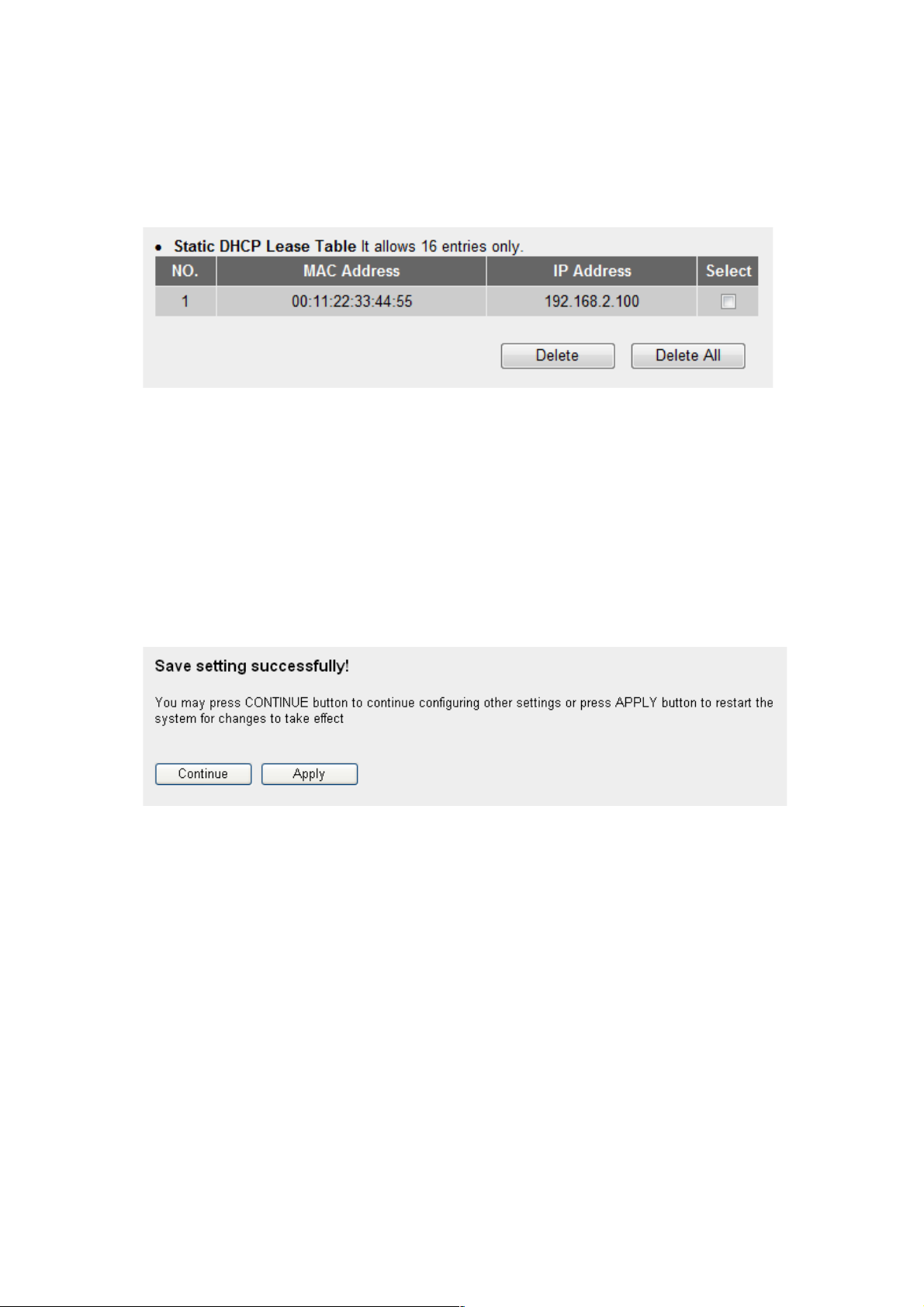
After you click “Add,” the MAC address and IP address mapping
will be added to the Static DHCP Leases Table section.
If you want to delete a specific item, check the “Select” box of a
MAC address and IP address mapping (1), then click “Delete” (2);
if you want to delete all mappings, click “Delete All” (3).
After you finish all LAN settings, click “Apply” at the bottom of this
page. After you click “Apply,” the following message will be
displayed on your Web browser:
Click “Continue” to go back and continue with the router setup
procedure, or click “Apply” to reboot the router so the settings will
take effect. (Wait for about 30 seconds while the router is
rebooting.)
1 2 3

63
2-7 Wireless LAN Configurations
If your computer, PDA, game console or other network device is
equipped with a wireless network interface, you can use the
wireless function of this router to let them connect to the Internet
and share resources with other computers with a wired LAN
connection. You can also use the built-in security functions to
protect your network from malicious intruders.
Click Wireless on the left side of the Web management interface,
and the message below will be displayed on your Web browser.
You must enable the wireless function of this router; otherwise, the
wireless interface of this router will not function. Select “Enable” (1),
then click “Apply” (2).
To disable the wireless function, select “Disable” (3), then click
“Apply” (2).
After you click “Apply,” the following message will be displayed on
your Web browser:
1 2 3

64
Click “Continue” to go back and continue with the router setup
procedure, or click “Apply” to reboot the router so the settings will
take effect. (Wait for about 30 seconds while the router is
rebooting.)
2-7-1 Basic Wireless Settings
Click Wireless on the left side of the Web management interface,
then click “Basic Settings.” The following message will be displayed
on your Web browser:
Below are descriptions of the options:
BAND (1): Select the radio band you want to use from the
drop down menu. The following information will
be displayed:
1
2 3 4
5

65
SSID (2): This is the name of the wireless router. You can
type any alphanumerical characters here
(maximum of 32 characters). ESSID is used to
identify your own wireless router from others
when there are other wireless routers in the
same area. The default SSID is “INTELLINET”;
2.4 GHz (B) 2.4GHz band only allows 802.11b wireless
network clients to connect to this router
(maximum transfer rate 11 Mbps).
2.4 GHz (N) 2.4GHz band only allows 802.11n wireless
network clients to connect to this router
(maximum transfer rate 150 Mbps).
2.4 GHz (B+G) 2.4GHz band only allows 802.11b and
802.11g wireless network clienst to connect
to this router (maximum transfer rate 11
Mbps for 802.11b clients; 54 Mbps for
802.11g clients).
2.4 GHz (G) 2.4GHz band only allows 802.11g wireless
network clienst to connect to this router
(maximum transfer rate 54 Mbps).
2.4 GHz (B+G+N) 2.4GHz band allows 802.11b, 802.11g and
802.11n wireless network clients to connect
to this router (maximum transfer rate 11
Mbps for 802.11b clients; 54 Mbps for
802.11g clients; 150 Mbps for 802.11n
clients).
NOTE: For 802.11b and 802.11g mode, the signals can be transmitted
only by antenna 1 (the antenna on the right side of the rear panel).
For 802.11n mode: The router is operating in a 2T2R Spatial
Multiplexing MIMO configuration. 2 antennas are for signal
transmitting and 2 antennas are for signal receiving.

66
it’s recommended to change default ESSID
name to one that is meaningful to you, such as
“myhome,” “office_room1,” etc.
Channel Number (3): Select a channel from the drop-down list.
Available channel numbers are 1 to 13 for
European countries; 1 to 11 for the U.S. You
can choose any channel number you want to
use, and almost all wireless clients can locate
the channel you’re using automatically without
any problem. However, it’s still useful to
remember the channel number you use. Some
wireless clients support manual channel
number select, which would help in certain
scenarios where there is some radio
communication problem.
Associated Clients (4): Click “Show Active Clients” and an “Active
Wireless Client Table” will pop up. You can see
the status of all active wireless stations that are
connecting to the router.
After you finish the wireless settings, click “Apply” and the following
message will be displayed on your Web browser:
NOTE: If you don’t have a special reason to limit the type of allowed
wireless client, it’s recommended to choose 2.4 GHz (B+G+N) to
maximize wireless client compatibility.
TIPS: You can try changing the channel number to another one if you
think the data transfer rate is too slow. There could be some other
wireless routers using the same channel, which will disturb the radio
communication between wireless clients and the wireless router.

67
Click “Continue” to go back and continue with the router setup
procedure, or click “Apply” to reboot the router so the settings will
take effect. (Wait for about 30 seconds while the router is
rebooting.)
2-7-2 Advanced Wireless Settings
This router provides some advanced control of wireless parameters.
Click Wireless on the left side of the Web management interface,
then click “Advanced Settings” and the following message will be
displayed on your Web browser:
1
2
3
4
5
7
8
6
9
10
11
12
13

68
Below are descriptions of the options:
Fragment Set the threshold of the wireless radio.
Threshold (1): Do not modify the default value if you don’t
know what it does (default value is 2346).
RTS Threshold (2): Set the RTS threshold of the wireless radio. Do
not modify the default value if you don’t
know what it does (default value is 2347).
Beacon Interval (3): Set the beacon interval of the wireless radio.
Do not modify the default value if you don’t
know what it does (default value is 100).
DTIM Period (4): Set the DTIM period of the wireless radio. Do
not modify the default value if you don’t
know what it does (default value is 3).
Data Rate (5): Set the wireless data transfer rate to a certain
value. Since most wireless devices will
negotiate with each other and pick a proper
data transfer rate automatically, it’s not
necessary to change this value unless you
know what will happen after modification.
N Data Rate (6): Same as above, but only for 802.11n clients.
Channel Width (7): Set the channel width. Do not modify the
default value if you don’t know what it does
(default setting is “Auto 20/40 MHz”).
Preamble Type (8): Set the type of preamble. Do not modify the
default value if you don’t know what it does
(default setting is “Short Preamble”).
Broadcast ESSID (9): Decide if the wireless router will broadcast its
own ESSID or not. You can hide the ESSID of
69
your wireless router (set the option to “Disable”)
so only those who know the ESSID of your
wireless router can connect.
CTS Protect (10): Enabling this setting will reduce the chance of
radio signal collisions between 802.11b and
802.11g/n wireless access points. It’s
recommended to set this option to “Auto” or
“Always.” However, if you set to “None,” your
wireless router should be able to work fine.
Tx Power (11): You can set the output power of the wireless
radio. Unless you’re using this wireless router in
a really big space, you may not have to set
output power to 100%. This will enhance
security (distant malicious/unknown users
won’t be able to reach your wireless router).
WMM (12): Wi-Fi MultiMedia will enhance the data transfer
performance of multimedia content when it’s
being transferred over the wireless network. If
you don’t know what it is or aren’t sure if
you need it, it’s safe to set this option to
“Enable” (though the default is “Disable”).
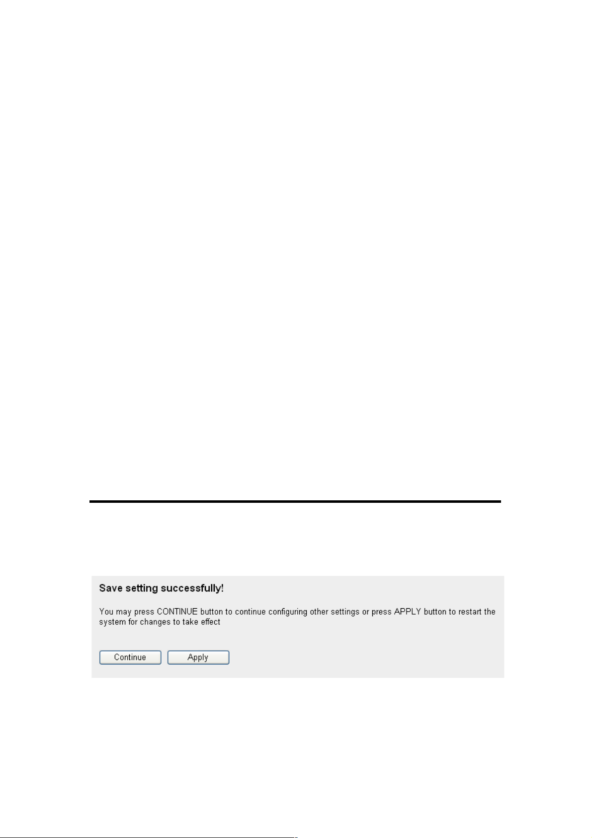
After you finish these wireless settings, click “Apply” (13) and the
following message will be displayed on your Web browser:
Click “Continue” to go back and continue with the router setup
procedure, or click “Apply” to reboot the router so the settings will
take effect. (Wait for about 30 seconds while the router reboots.)

70
2-7-3 Wireless Security
It’s very important to set wireless security settings properly! If
you don’t, hackers and malicious users can reach your network and
valuable data without your consent, causing a serious security
problem.
Click Wireless on the left side of the Web management interface,
then click “Security Settings.”
Select an encryption method from the “Encryption” drop-down
menu. There are four options:
2-7-3-1 Disable Wireless Security
When you select this mode, data encryption is disabled and every
wireless device in proximity will be able to connect to your wireless
router if no other security measure is enabled (such as MAC
address access control or disabling ESSID broadcast).
Only use this option when you really want to allow everyone
to use your wireless router and you don’t care if someone
reads the data you transfer over the network without your
consent.
2-7-3-2 WEP (Wired Equivalent Privacy)
When you select this mode, the wireless router will use WEP
encryption and the following setup menu will be shown on your
Web browser:

71
Below are descriptions of the options:
Key Length (2): There are two types of WEP key length: 64-bit
and 128-bit. “128-bit” is safer than “64-bit” but
will reduce some data transfer performance.
Key Format (3): There are two types of key format: ASCII and
Hex. When you select a key format, the number
of characters of the key will be displayed. For
example, if you select “64-bit” as the key length,
and “Hex” as the key format, you’ll see the
message at the right of “Key Format” is “Hex
(10 characters),” which means the length of the
WEP key is 10 characters.
Default Tx Key (4): You can set up to four sets of WEP keys, and
you can decide which key is being used by
default here. If unsure, select “Key 1.”
Encryption Key Input WEP key characters here. The number of
1 to 4 (5-8): characters must be the same as the number
displayed in the “‘Key Format” field. You can
use any alphanumerical characters (0-9, a-z,
and A-Z) if you select “ASCII” key format; if you
select “Hex,” you can use characters 0-9, a-f
and A-F. You must enter at least one encryption
1
2
3
5
7
6
9
4
8
10

72
key here; if you enter multiple WEP keys, they
should all be different.
Enable 802.1x IEEE 802.1x is an authentication protocol.
Authentication (9): Every user must use a valid account to log in to
this wireless router before accessing the
wireless LAN. The authentication is processed
by a RADIUS server. This mode only
authenticates users by IEEE 802.1x, but it does
not encrypt the data during communication. If
there is a RADIUS server in your environment,
enable this function. Check this box and
another sub-menu will appear:
RADIUS Server Enter the IP address of the RADIUS server
IP Address (11): here.
RADIUS Server Enter the port number the RADIUS server
Port (12): here.
RADIUS Server Enter the RADIUS server password here.
Password (13):
11
12
13
TIPS: Some examples of WEP keys (Don’t use these; use your own!):
ASCII (5 characters): pilot phone 23561 2Hyux #@xmL
ASCII (13 characters): digitalFAMILY 82Jh26xHy3m&n
Hex (10 characters): 287d2aa732 1152dabc85
Hex (26 characters): 9284bcda8427c9e036f7abcd84
To improve security, don’t use words found in a dictionary or which
are too easy to remember! (“pilot” and “phone” are examples of bad
choices). Wireless clients will remember the WEP key, so you only
have to input the WEP key for a wireless client once.
73
After you finish the WEP settings, click “Apply” (10) and the
following will be displayed on your Web browser:
Click “Continue” to go back and continue with the router setup
procedure, or click “Apply” to reboot the router so the settings will
take effect. (Wait for about 30 seconds while the router reboots.)
2- 7-3-3 W i-Fi Pr otect ed Acce ss (WPA)
When you select this mode, the wireless router will use WPA
encryption, and the following setup menu will be shown on your
Web browser:
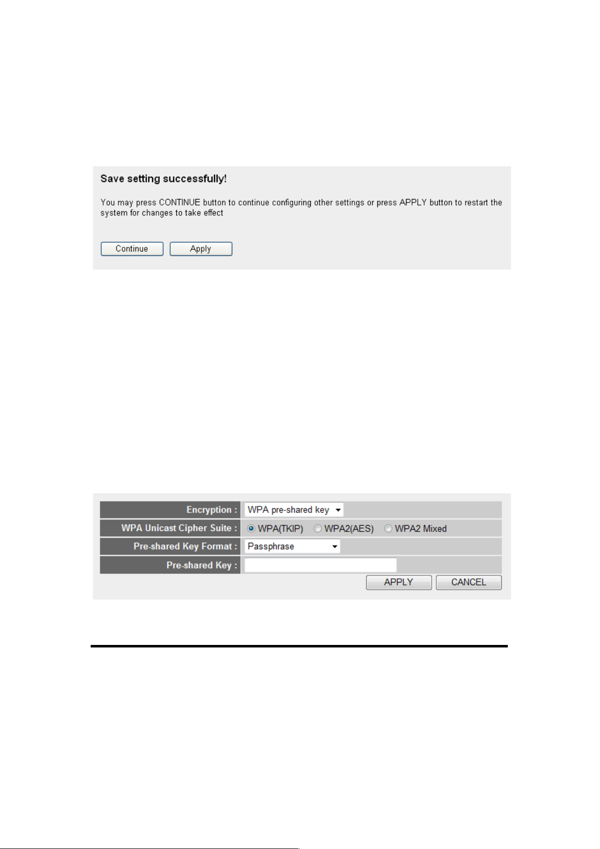
Below are descriptions of the options:
WPA Unicast Select a type of WPA cipher suite.
Cipher Suite (2): Options are “WPA (TKIP),” “WPA2 (AES)” and
“WPA2 Mixed.” You can select any one of them,
but you have to make sure your wireless client
supports the cipher you select.
1
2
3
5
4

74
Pre-shared Select the type of pre-shared key. You
Key Format (3): can select Passphrase (8 or more
alphanumerical characters, up to 63), or Hex
(64 characters of 0-9 and a-f).
Pre-shared Enter the WPA passphrase here.
Key (4): It’s not recommended to use a word that
can be found in a dictionary due to security
reasons.
After you finish the WPA Pre-shared Key settings, click “Apply” (5)
and the following will be displayed on your Web browser:
Click “Continue” to go back and continue with the router setup
procedure, or click “Apply” to reboot the router so the settings will
take effect. (Wait for about 30 seconds while the router reboots.)
2- 7-3-4 W PA RADI US
If you have a RADIUS server, this router can work with it and
provide safer wireless authentication.
NOTE: Some wireless clients (especially those manufactured before
year 2003) only support WEP or WPA (TKIP) cipher. A driver upgrade
would be needed for those clients to use WPA and WPA2 encryption.

75
Below are descriptions of the options:
WPA Unicast Select a type of WPA cipher suite.
Cipher Suite (2): Options are “WPA (TKIP),” “WPA2 (AES)” and
“WPA2 Mixed.” You can select any one of them,
but you have to make sure your wireless client
supports the cipher you selected.
RADIUS Server Enter the IP address of your RADIUS
IP address (3): authentication server here.
RADIUS Server Enter the port number of your RADIUS
Port (4): authentication server here. Default is 1812.
RADIUS Server Enter the password for your RADIUS
Password (5): authentication server here.
After you finish the settings, click “Apply” (6) and the following
message will be displayed on your Web browser:
Click “Continue” to go back and continue with the router setup
procedure, or click “Apply” to reboot the router so the settings will
take effect. (Wait for about 30 seconds while the router reboots.)
1
3
4
2
5
6

76
2-7-4 Wireless Access Control
This function will help you to prevent unauthorized users from
connecting to your wireless router; only those wireless devices who
have the MAC address you assigned here can gain access to your
wireless router. You can use this function with other security
measures described in previous section, to create a safer wireless
environment.
Up to 20 MAC addresses can be assigned by using this function.
Click Wireless on the left side of the Web management interface,
then click “Access Control.” The following message will be
displayed on your Web browser:
All allowed MAC addresses will be displayed in “MAC Address
Filtering Table” (1).
Below are descriptions of the options:
Delete (2): If you want to delete a specific MAC address
entry, check the “Select” box of the MAC
address you want to delete, then click “Delete.”
(You can select more than one MAC address).
Delete All (3): If you want to delete all the MAC addresses
listed here, click “Delete All.”
1 2 3
4
9
5

77
Enable Wireless To enforce MAC address filtering, check
Access Control (4): “Enable Wireless Access Control.” When this
item is unchecked, the router will not enforce
MAC address filtering of wireless clients.
MAC Address (5): Input the MAC address of your wireless devices
here. Dashes ( - ) and colons ( : ) are not
required; i.e., if the MAC address label of your
wireless device is “aa-bb-cc-dd-ee-ff” or
“aa:bb:cc:dd:ee:ff.” just input “aabbccddeeff.”
Comment (6): You can input any text here as a comment about
this MAC address, like “ROOM 2A Computer.”
Enter up to 16 alphanumerical characters here.
This is optional and you can leave it blank.
Add (7): Click “Add” to add the MAC address and
associated comments to the MAC address
filtering table.
Clear (8): Click “Clear” to remove the value you entered in
“MAC Address” and “Comment” fields.
After you finish the settings, click “Apply” (9) and the following
message will be displayed on your Web browser:
Click “Continue” to go back and continue with the router setup
procedure, or click “Apply” to reboot the router so the settings will
take effect. (Wait for about 30 seconds while the router reboots.)
If you want to reset all settings on this page back to previously
saved values, click “Cancel.”
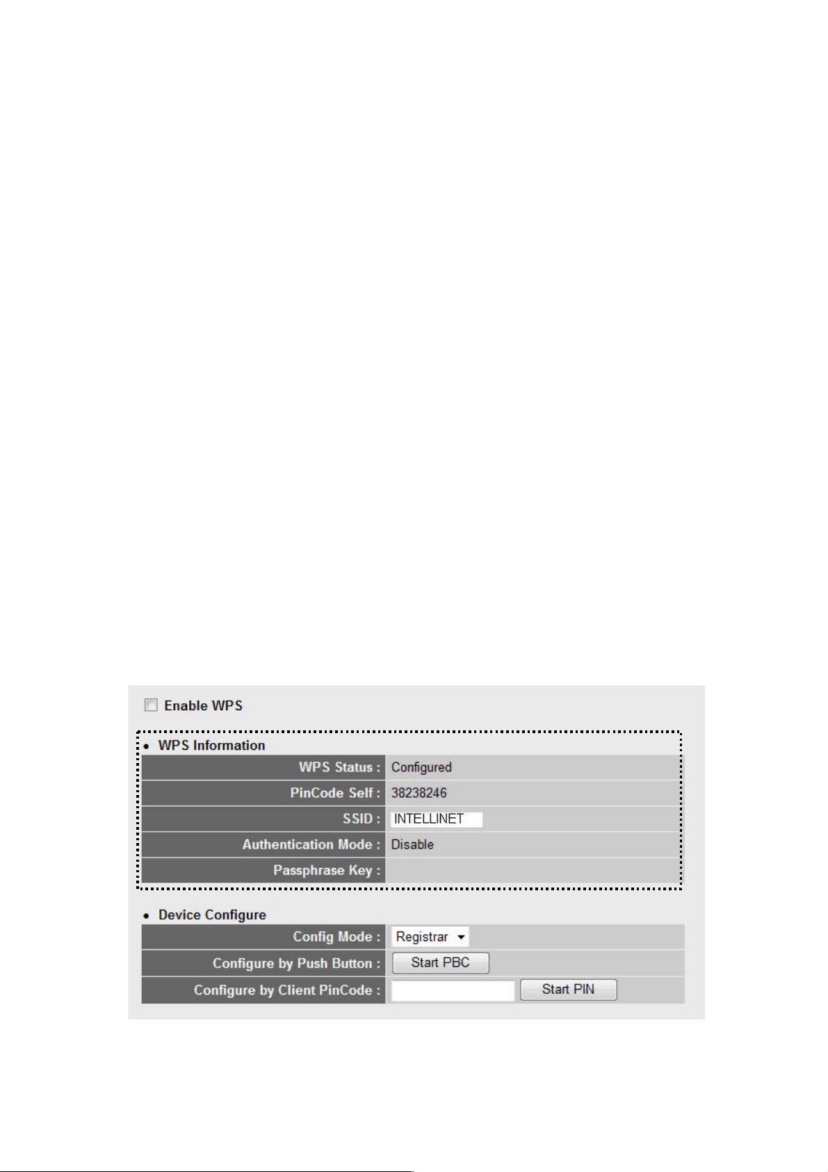
78
2- 7-5 W i- Fi Pr ot ected S etup (W PS)
Wi-Fi Protected Setup (WPS) is the simplest way to build a
connection between wireless network clients and this wireless
router. You don’t have to select an encryption mode or input a long
encryption passphrase every time you need to set up a wireless
client: You only need to press a button on the wireless client and
this wireless router, and the WPS will do the rest for you.
This wireless router supports two types of WPS: Push-Button
Configuration (PBC) and PIN Code. If you want to use PBC, you
need to push a specific button on the wireless client to start WPS
mode, and switch this wireless router to WPS mode, too. You can
push the Reset/WPS button on this wireless router or click “Start
PBC” on the Web configuration interface to do this; if you want to
use PIN Code, you need to know the PIN code of the wireless client
and switch it to WPS mode, then provide the PIN code of the
wireless client you want to connect to this wireless router.
Click Wireless on the left side of the Web management interface,
then click “WPS.” The following message will be displayed on your
Web browser:
1
4
5

79
Below are descriptions of the options:
Enable WPS (1): Check this box to enable WPS function;
uncheck it to disable WPS.
Wi-Fi Protected WPS-related system information will be
Setup Info (2): displayed here:
WPS Status: If the wireless security (encryption)
function of this wireless router is properly set,
you’ll see “Configured.” If the function hasn’t
been set, you’ll see “unConfigured.”
Self PIN code: This is the WPS PIN code of this
wireless router. This code is useful when you
need to build a wireless connection using WPS
with other WPS-enabled wireless devices.
SSID: The SSID of this wireless router will be
displayed here.
Authentication Mode: The wireless security
authentication mode of this wireless router will
be displayed here. If you don’t enable the
security function of the wireless router before
WPS is activated, the router will auto-set the
security to WPA2 Mixed and generate a set of
passphrase keys for WPS connection.
Passphrase Key: The wireless security key of
the router will be displayed here.
Config Mode (3): There are Registrar and Enrollee modes for the
WPS connection. When “Registrar” is selected,
the wireless clients will follow the router’s
wireless settings for WPS connection. When
“EnrollEe” is selected, the router will follow the
wireless settings of the wireless client for WPS
connection.

80
Configure by Click “Start PBC" to start Push Button-style
Push Button (4): WPS setup procedure. This wireless router will
wait for WPS requests from wireless clients for
2 minutes. The WLAN LED on the wireless
router will be lit for 2 minutes when this wireless
router is waiting for incoming WPS requests.
Configure Enter the PIN code of the wireless client you
by Client want to connect to, and click “Start PIN.”
PinCode (5): The WLAN LED on the wireless router will be lit
when this wireless router is waiting for incoming
WPS requests.
2- 7-6 S ec urity Tips for Wireless Network
Here are some quick tips to help you improve the security level of
your wireless network:
1. Never use simple words (like school, apple and computer) as
WEP encryption or WPA passphrases.
2. A complicated (lengthy combination of numbers, letters and
even symbols) WEP key and WPA passphrase is much safer
than a simple and short one. Remember that the wireless client
is able to keep the key or passphrase for you, so you only have
to input the complicated key or passphrase once. It’s not too
much trouble, and it will greatly improve your security level.
3. You can hide the ESSID of this router by setting “Broadcast
ESSID” to “Disable.” Your wireless router will not be found by
other people in proximity if they’re just using the AP scanning
function of their wireless client, and this can reduce the chance
of being hacked.
4. Use Access Control described in Section 2-7-4 so those who are
not on your list will not be able to connect to your network.

81
Chapter III Advanced Functions
3-1 Q ualit y of Servi ce (Q oS)
Quality of service provides an efficient way for computers on the
network to share the Internet bandwidth with a promised quality of
Internet service. Without QoS, all computers and devices on the
network will compete with each other to get Internet bandwidth, and
some applications which require guaranteed bandwidth (like video
streaming and network telephone) will be affected, possibly
resulting in the interruption of video/audio transfer.
With this function, you can limit the maximum bandwidth or give a
guaranteed bandwidth for a specific computer to avoid this and
other problems.
3- 1-1 Basic QoS Se ttings
Click “QoS” on the left side of the Web management interface and
the following message will be displayed on your Web browser:
Below are descriptions of the options:
1
2
4
5 6 7 8 9
10
11

82
Enable QoS (1): Check this box to enable the QoS function;
de-select this box if you don’t want to enforce
QoS bandwidth limitations.
Total Download You can set the limit of total download
Bandwidth (2): bandwidth in kbits. To disable the download
bandwidth limitation, enter “0” here.
Total Upload You can set the limit of total upload
Bandwidth (3): bandwidth in kbits. To disable the upload
bandwidth limitation enter “0” here.
Current QoS All existing QoS rules will be displayed here.
Table (4):
Add (5): Click “Add” to add a new QoS rule (see Section
3-1-2 below).
Edit (6): If you want to modify the content of a specific
rule, check the “Select” box of the rule you want
to edit, then click “Edit.” Only one rule should
be selected a time! If you didn’t select a rule
before clicking “Edit,” you’ll be prompted to add
a new rule.
Delete You can delete selected rules by clicking this
Selected (7): button. You can select one or more rules to
delete by checking the “Select” boxes of the
rule(s) you want to delete. If the QoS table is
empty, this button will be grayed out and
can not be clicked.
Delete All (8): By clicking this button, you can delete all rules
currently in the QoS table. If the QoS table is
empty, this button will be grayed out and
can not be clicked.
Move Up (9): You can pull up the priority of the QoS rule you

83
selected by clicking this button.
Move Down (10): You can lower the priority of the QoS rule you
selected by clicking this button.
After you finish the settings, click “Apply” (11) and the following
message will be displayed on your Web browser:
Click “Continue” to go back and continue with the router setup
procedure, or click “Apply” to reboot the router so the settings will
take effect. (Wait for about 30 seconds while the router reboots.)
If you want to reset all settings on this page back to previously
saved values, click “Cancel.”
3- 1-2 A dd ing a N ew QoS Ru le
After you click “Add” in the QoS menu, the following message will
appear:
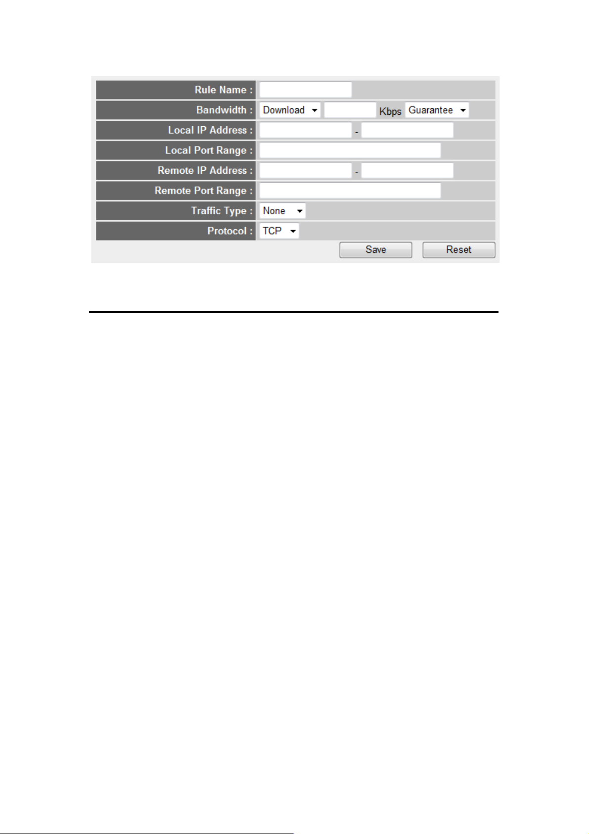
84
Below are descriptions of the options:
Rule Name (a): Enter a name for this QoS rule (up to 15
alphanumerical characters).
Bandwidth (b): Set the bandwidth limitation of this QoS rule.
You need to select the data direction of this rule
(Upload of Download), and the speed of
bandwidth limitation in kbps, then select the
type of QoS: “Guarantee” (guaranteed usable
bandwidth for this rule) or “max” (set the
maximum bandwidth for the application allowed
by this rule).
Local IP Specify the local (source) IP address that will
Address (c): be affected by this rule. Enter the starting IP
address in the left field and enter the end IP
address in the right field to define a range of IP
addresses, or just enter the IP address in the
left field to define a single IP address.
Local Port Enter the range of the local (source) port
Range (d): numbers that will be affected by this rule. If you
want to apply this rule on ports 80 to 90, enter
“80-90”; if you want to apply this rule on a single
port, just enter the port number, such as “80.”
a b c
d
e
f
g
h
i

85
Remote IP Specify the remote (destination) IP address
Address: (e): that will be affected by this rule. Input the
starting IP address in the left field and input the
end IP address in the right field to define a
range of IP addresses, or just input the IP
address in the left field to define a single IP
address.
Remote Port Input the range of remote (destination) port
Range (f): number that will be affected by this rule. If you
want to apply this rule on ports 80 to 90, input
“80-90”; if you want to apply this rule on a single
port, just input the port number, such as “80.” If
the remote (destination) IP address and/or port
number is universal, just leave it blank.
Traffic Type (g): Select the traffic type of this rule. Options are
“None,” “SMTP,” “HTTP,” “POP3” and “FTP.”
You can select a specific traffic type for this rule:
If you want to make this rule an IP addressbased rule (apply the limitation on all traffics
from/to the specified IP address/port number),
select “None.”
Protocol (h): Select the protocol type of this rule. Options are
“TCP” and “UDP.” If you don’t know what
protocol your application uses, try “TCP” first
and switch to “UDP” if this rule doesn’t seem to
work.
After you finish the settings, click “Save” (i). You’ll be brought back
to the previous menu, and the rule you just set will appear in the
current QoS table; if you did anything wrong, you’ll get an error
message when you click “Save.” Correct your entry as instructed by
the error message.
If you want to erase all the values you just entered, click “Reset.”

86
3-2 N etwor k Address Translation (NAT)
Network address translations solve the problem of sharing a single
IP address on multiple computers. Without NAT, all computers must
be assigned a valid Internet IP address to get connected to the
Internet, but Internet service providers provide only a very few IP
addresses to each user. Therefore, it’s necessary to use NAT
technology to share a single Internet IP address on multiple
computers on a local network so everyone can get connected to the
Internet.
3- 2-1 B as ic NAT Setting s
Click “NAT” on the left side of the Web management interface, and
the following message will be displayed on your Web browser:
To enable the NAT function, select “Enable”; to disable, select
“Disable.”
After you make the selection, click “Apply” (2) and the following
message will be displayed on your Web browser:
1
2

87
Click “Continue” to go back and continue with the router setup
procedure, or click “Apply” to reboot the router so the settings will
take effect. (Wait for about 30 seconds while the router reboots.)
3- 2-2 P or t For wa rding
This function allows you to redirect a single port or consecutive
ports of an Internet IP address to the same port of the IP address
on a local network. The port number(s) of the Internet IP address
and private IP address (the IP address on the local network) must
be the same. If the port numbers of the Internet IP address and
private IP address are different, use the Virtual Server function
described in the next section.
Click “NAT” on the left side of the Web management interface, then
click “Port Forwarding.” The following message will be displayed on
your Web browser:
3 4 5
6
7
8
10
11
12
13
2
1

88
Below are descriptions of the options:
Enable Port Check this box to enable port mapping;
Forwarding (1): uncheck this box to disable port mapping.
Private IP (2): Input the IP address of the computer on the
local network that provides Internet service.
Computer Name (3): Pull down the menu and all the computers
connected to the router will be listed here. You
can select the computer name without checking
the IP address of the computer.
Type (4): Select the type of connection: “TCP” or “UDP.”
If you’re not sure, select “Both.”
Port Range (5): Input the starting port number in the left field
and input the ending port number in the right
field. If you only want to redirect a single port
number, just enter the port number in the left
field.
Comment (6): Input any text to describe this mapping, up to 16
alphanumerical characters.
Add (7): Add the mapping to the port forwarding table.
Reset (8): Remove all entered values.
Port Forwarding All existing port forwarding mappings will
Table (9): be displayed here.
Delete (10): Select a port forwarding mapping by clicking the
“Select” box of the mapping, then click “Delete
Selected” to remove the mapping. If there’s no
existing mapping, this button will be grayed out.
Delete All (11): Delete all mappings in the virtual server table.

89
Reset (12): Unselect all mappings.
After you finish the settings, click “Apply” (13) and the following
message will be displayed on your Web browser:
Click “Continue” to go back and continue with the router setup
procedure, or click “Apply” to reboot the router so the settings will
take effect. (Wait for about 30 seconds while the router reboots.)
If you want to reset all settings on this page back to previously
saved values, click “Cancel.”
3- 2-3 V ir tual Se rver
This function allows you to redirect a port on the Internet IP address
(on a WAN port) to a specified port of an IP address on the local
network so you can set up an Internet service on the computer on
the local network without exposing it on the Internet directly. You
can also build many sets of port redirection to provide many
different Internet services on different local computers via a single
Internet IP address.
Click “NAT” on the left side of the Web management interface, then
click “Virtual Server.” The following message will be displayed on
your Web browser:

90
Below are descriptions of the options:
Enable Virtual Check this box to enable the virtual server;
Server (1): uncheck this box to disable it.
Private IP (2): Input the IP address of the computer which
provides Internet service.
Computer Name (3): Pull down the menu and all the computers
connected to the router will be listed here. You
can select the computer name without checking
the IP address of the computer.
Private Port (4): Input the port number of the IP address
which provides Internet service.
Type (5): Select the type of connection: “TCP” or “UDP.” If
you’re not sure, select “Both.”
Public Port (6): Select the port number of the Internet IP
address that will be redirected to the port
number of the local IP address defined above.
Comment (7): Input any text to describe this mapping, up to 16
alphanumerical characters.
Add (8): Add the mapping to the virtual server table.
1
2
3 4 5
8 9 10
11
12
13
14
7
6

91
Reset (9): Remove all entered values.
Virtual Server All existing virtual server mappings will be
Table (10): displayed here.
Delete (11): Select a virtual server mapping by clicking the
“Select” box of the mapping, then click “Delete
Selected” to remove the mapping. If there’s no
existing mapping, this button will be grayed out.
Delete All (12): Delete all mappings in the virtual server table.
Reset (13): Unselect all mappings.
After you finish the settings, click “Apply” (14) and the following
message will be displayed on your Web browser:
Click “Continue” to go back and continue with the router setup
procedure, or click “Apply” to reboot the router so the settings will
take effect. (Wait for about 30 seconds while the router reboots.)
If you want to reset all settings on this page back to previously
saved values, click “Cancel.”

92
3- 2-4 P or t Mappi ng fo r Speci al Appl ication s
Some applications require more than one connection a time; these
applications won’t work with simple NAT rules. In order to make
these applications work, you can use this function.
Below are descriptions of the options:
Enable (1): Check this box to enable special applications;
uncheck this box to disable the virtual server.
IP Address (2): Input the IP address of the computer you want
to open the ports.
Computer Name (3): Pull down the menu and all the computers
connected to the router will be listed here. You
can select the computer name without checking
the IP address of the computer.
TCP Port to Open (4): This is the outgoing (Outbound) range of
TCP port numbers for this particular application.
UDP Port to Open (5): This is the outgoing (Outbound) range of
UDP port numbers for this particular
application.
Comment (6): Enter a description of this setting.
1
2 3 4
5
8
9
10
11
12
7
6
13
14

93
Popular This section lists the more popular applications
Applications (7): that require multiple connections. Select an
application from the “Popular Applications”
section and click “Add” to save the setting to
“Current Trigger-Port Table.”
Add (8): Add the setting to the “Current Trigger-Port
Table.”
Reset (9): Click to clear all the above settings.
Current Trigger - All the settings for the special applications will
Port Table (10): be listed here. If you want to remove some
Special Application settings from the "Current
Trigger-Port Table," select the Special
Application settings you want to remove in the
table and then click "Delete Selected." If you
want to remove all Special Application settings
from the table, just click "Delete All." Click
"Reset" to clear your current selections.
Delete (11): Select a special application by clicking the
“Select” box of the mapping, then click “Delete
Selected” to remove the setting. If there’s no
setting here, this button will be grayed out.
Delete All (12): Delete all settings in the trigger port table.
Reset (13): Unselect all settings.
NO TE: Only one LAN client can use a particular special
application at a time.
After you finish the settings, click “Apply” (14) and the following
message will be displayed on your Web browser:
 Loading...